


TL-SG2210P/TL-SG2216/TL-SG2424/
TL-SG2424P/TL-SG2452
Gigabit Smart Switch
REV1.3.0
1910011016

COPYRIGHT & TRADEMARKS
Specifications are subject to change without notice.  is a registered trademark of TP-LINK TECHNOLOGIES CO., LTD. Other brands and product names are trademarks or registered trademarks of their respective holders.
No part of the specifications may be reproduced in any form or by any means or used to make any derivative such as translation, transformation, or adaptation without permission from TP-LINK TECHNOLOGIES CO., LTD. Copyright © 2014 TP-LINK TECHNOLOGIES CO., LTD. All rights reserved.
http://www.tp-link.com
FCC STATEMENT
This equipment has been tested and found to comply with the limits for a Class A digital device, pursuant to part 15 of the FCC Rules. These limits are designed to provide reasonable protection against harmful interference when the equipment is operated in a commercial environment. This equipment generates, uses, and can radiate radio frequency energy and, if not installed and used in accordance with the instruction manual, may cause harmful interference to radio communications. Operation of this equipment in a residential area is likely to cause harmful interference in which case the user will be required to correct the interference at his own expense.
This device complies with part 15 of the FCC Rules. Operation is subject to the following two conditions:
1)This device may not cause harmful interference.
2)This device must accept any interference received, including interference that may cause undesired operation.
Any changes or modifications not expressly approved by the party responsible for compliance could void the user’s authority to operate the equipment.
CE Mark Warning
This is a class A product. In a domestic environment, this product may cause radio interference, in which case the user may be required to take adequate measures.
Продукт сертифіковано згідно с правилами системи УкрСЕПРО на відповідність вимогам нормативних документів та вимогам, що передбачені чинними законодавчими актами України.
III

Safety Information
When product has power button, the power button is one of the way to shut off the product; When there is no power button, the only way to completely shut off power is to disconnect the product or the power adapter from the power source.
Don’t disassemble the product, or make repairs yourself. You run the risk of electric shock and voiding the limited warranty. If you need service, please contact us.
Avoid water and wet locations.
This product can be used in the following countries:
AT |
BG |
BY |
CA |
CZ |
DE |
DK |
EE |
|
|
|
|
|
|
|
|
ES |
FI |
FR |
GB |
GR |
HU |
IE |
IT |
|
|
|
|
|
|
|
|
LT |
LV |
MT |
NL |
NO |
PL |
PT |
RO |
|
|
|
|
|
|
|
|
RU |
SE |
SK |
TR |
UA |
US |
|
|
|
|
|
|
|
|
|
|
IV
|
|
|
CONTENTS |
Package Contents .......................................................................................................................... |
1 |
||
Chapter 1 About this Guide........................................................................................................... |
2 |
||
1.1 |
Intended Readers ......................................................................................................... |
2 |
|
1.2 |
Conventions.................................................................................................................. |
2 |
|
1.3 |
Overview of This Guide ................................................................................................ |
2 |
|
Chapter 2 |
Introduction .................................................................................................................. |
6 |
|
2.1 |
Overview of the Switch ................................................................................................. |
6 |
|
2.2 |
Main Features............................................................................................................... |
6 |
|
2.3 |
Appearance Description ............................................................................................... |
6 |
|
2.3.1 |
Front Panel ........................................................................................................ |
6 |
|
2.3.2 |
Rear Panel ....................................................................................................... |
10 |
|
Chapter 3 Login to the Switch..................................................................................................... |
12 |
||
3.1 |
Login |
........................................................................................................................... |
12 |
3.2 |
Configuration .............................................................................................................. |
12 |
|
Chapter 4 |
System ....................................................................................................................... |
14 |
|
4.1 |
System Info................................................................................................................. |
14 |
|
4.1.1 ............................................................................................. |
System Summary |
14 |
|
4.1.2 ........................................................................................... |
Device Description |
15 |
|
4.1.3 .................................................................................................... |
System Time |
16 |
|
4.1.4 ....................................................................................... |
Daylight Saving Time |
17 |
|
4.1.5 ......................................................................................................... |
System IP |
18 |
|
4.2 |
User Management ...................................................................................................... |
19 |
|
4.2.1 ........................................................................................................ |
User Table |
19 |
|
4.2.2 ...................................................................................................... |
User Config |
20 |
|
4.3 |
System ..............................................................................................................Tools |
21 |
|
4.3.1 ................................................................................................. |
Config Restore |
21 |
|
4.3.2 .................................................................................................. |
Config Backup |
22 |
|
4.3.3 ........................................................................................... |
Firmware Upgrade |
22 |
|
4.3.4 ................................................................................................ |
System Reboot |
23 |
|
4.3.5 ................................................................................................... |
System Reset |
23 |
|
4.4 |
Access ..........................................................................................................Security |
24 |
|
4.4.1 ................................................................................................. |
Access Control |
24 |
|
4.4.2 ....................................................................................................... |
SSL Config |
25 |
|
4.4.3 ...................................................................................................... |
SSH Config |
27 |
|
Chapter 5 |
Switching.................................................................................................................... |
33 |
|
5.1 |
Port ............................................................................................................................. |
|
33 |
III
5.1.1 |
Port Config ....................................................................................................... |
33 |
|
5.1.2 |
Port Mirror ........................................................................................................ |
34 |
|
5.1.3 |
Port Security .................................................................................................... |
36 |
|
5.1.4 |
Port Isolation .................................................................................................... |
38 |
|
5.1.5 |
Loopback Detection ......................................................................................... |
39 |
|
5.2 |
LAG ............................................................................................................................ |
|
40 |
5.2.1 |
LAG Table ........................................................................................................ |
41 |
|
5.2.2 |
Static LAG ........................................................................................................ |
42 |
|
5.2.3 |
LACP Config .................................................................................................... |
43 |
|
5.3 |
Traffic |
Monitor............................................................................................................. |
45 |
5.3.1 |
Traffic Summary............................................................................................... |
45 |
|
5.3.2 |
Traffic Statistics ................................................................................................ |
46 |
|
5.4 |
MAC Address.............................................................................................................. |
47 |
|
5.4.1 |
Address Table .................................................................................................. |
48 |
|
5.4.2 |
Static Address .................................................................................................. |
49 |
|
5.4.3 |
Dynamic Address ............................................................................................. |
50 |
|
5.4.4 |
Filtering Address .............................................................................................. |
52 |
|
5.5 |
DHCP Filtering............................................................................................................ |
53 |
|
Chapter 6 |
VLAN.......................................................................................................................... |
|
57 |
6.1 |
802.1Q VLAN.............................................................................................................. |
58 |
|
6.1.1 |
VLAN Config .................................................................................................... |
59 |
|
6.2 |
Application Example for 802.1Q VLAN ....................................................................... |
61 |
|
Chapter 7 |
Spanning Tree............................................................................................................ |
63 |
|
7.1 |
STP Config ................................................................................................................. |
68 |
|
7.1.1 |
STP Config....................................................................................................... |
68 |
|
7.1.2 |
STP Summary.................................................................................................. |
70 |
|
7.2 |
Port Config.................................................................................................................. |
70 |
|
7.3 |
MSTP Instance ........................................................................................................... |
72 |
|
7.3.1 |
Region Config .................................................................................................. |
72 |
|
7.3.2 |
Instance Config ................................................................................................ |
73 |
|
7.3.3 |
Instance Port Config......................................................................................... |
74 |
|
7.4 |
STP Security............................................................................................................... |
76 |
|
7.4.1 |
Port Protect ...................................................................................................... |
76 |
|
7.4.2 |
TC Protect........................................................................................................ |
78 |
|
7.5 |
Application Example for STP Function ....................................................................... |
79 |
|
Chapter 8 |
Multicast..................................................................................................................... |
83 |
|
8.1 |
IGMP Snooping .......................................................................................................... |
85 |
|
|
|
IV |
|
8.1.1 |
Snooping Config .............................................................................................. |
86 |
|
8.1.2 |
Port Config ....................................................................................................... |
87 |
|
8.1.3 |
VLAN Config .................................................................................................... |
88 |
|
8.1.4 |
Multicast VLAN ................................................................................................ |
90 |
|
8.2 |
Multicast IP ................................................................................................................. |
93 |
|
8.2.1 |
Multicast IP Table ............................................................................................. |
94 |
|
8.2.2 |
Static Multicast IP ............................................................................................. |
94 |
|
8.3 |
Multicast Filter............................................................................................................. |
95 |
|
8.3.1 |
IP - Range .......................................................................................................... |
96 |
|
8.3.2 |
Port Filter ......................................................................................................... |
96 |
|
8.4 |
Packet Statistics.......................................................................................................... |
98 |
|
Chapter 9 |
QoS |
.......................................................................................................................... |
100 |
9.1 |
DiffServ..................................................................................................................... |
103 |
|
9.1.1 .................................................................................................... |
Port Priority |
103 |
|
9.1.2 ..................................................................................... |
802.1P/CoS mapping |
105 |
|
9.1.3 ................................................................................................. |
DSCP Priority |
106 |
|
9.1.4 .............................................................................................. |
Schedule Mode |
108 |
|
9.2 |
Bandwidth ....................................................................................................Control |
109 |
|
9.2.1 ....................................................................................................... |
Rate Limit |
109 |
|
9.2.2 ................................................................................................. |
Storm Control |
110 |
|
9.3 |
Voice ..............................................................................................................VLAN |
112 |
|
9.3.1 ................................................................................................. |
Global Config |
114 |
|
9.3.2 ..................................................................................................... |
Port Config |
115 |
|
9.3.3 ..................................................................................................... |
OUI Config |
116 |
|
Chapter 10 ACL .......................................................................................................................... |
|
118 |
|
10.1 |
ACL ...............................................................................................................Config |
118 |
|
10.1.1 ................................................................................................ |
ACL Summary |
118 |
|
10.1.2 .................................................................................................... |
ACL Create |
118 |
|
10.1.3 ....................................................................................................... |
MAC ACL |
119 |
|
10.1.4 ............................................................................................ |
Standard - IP ACL |
120 |
|
10.1.5 ............................................................................................... |
Extend - IP ACL |
120 |
|
10.2 |
Policy .............................................................................................................Config |
121 |
|
10.2.1 ............................................................................................. |
Policy Summary |
122 |
|
10.2.2 .................................................................................................. |
Policy Create |
122 |
|
10.2.3 ................................................................................................. |
Action Create |
123 |
|
10.3 |
Policy ...........................................................................................................Binding |
123 |
|
10.3.1 ................................................................................................. |
Binding Table |
123 |
|
|
|
|
V |
|
10.3.2 |
Port Binding ................................................................................................... |
124 |
|
10.3.3 |
VLAN Binding................................................................................................. |
124 |
10.4 |
Application Example for ACL .................................................................................... |
125 |
|
Chapter 11 PoE .......................................................................................................................... |
|
128 |
|
11.1 |
PoE Config ............................................................................................................... |
128 |
|
|
11.1.1 |
PoE Config..................................................................................................... |
129 |
|
11.1.2 |
PoE Profile..................................................................................................... |
131 |
11.2 |
PoE Time-Range ...................................................................................................... |
132 |
|
|
11.2.1 |
Time-Range Summary ................................................................................... |
133 |
|
11.2.2 |
PoE Time-Range Create................................................................................ |
133 |
|
11.2.3 |
PoE Holiday Config........................................................................................ |
134 |
Chapter 12 SNMP....................................................................................................................... |
136 |
||
12.1 |
SNMP Config ............................................................................................................ |
138 |
|
|
12.1.1 |
Global Config ................................................................................................. |
138 |
|
12.1.2 |
SNMP View.................................................................................................... |
139 |
|
12.1.3 |
SNMP Group.................................................................................................. |
140 |
|
12.1.4 |
SNMP User .................................................................................................... |
141 |
|
12.1.5 |
SNMP Community.......................................................................................... |
143 |
12.2 |
Notification................................................................................................................ |
145 |
|
12.3 |
RMON....................................................................................................................... |
146 |
|
|
12.3.1 |
History Control ............................................................................................... |
147 |
|
12.3.2 |
Event Config .................................................................................................. |
148 |
|
12.3.3 |
Alarm Config .................................................................................................. |
149 |
Chapter 13 LLDP ........................................................................................................................ |
|
151 |
|
13.1 |
Basic Config ............................................................................................................. |
155 |
|
|
13.1.1 |
Global Config ................................................................................................. |
155 |
|
13.1.2 |
Port Config ..................................................................................................... |
156 |
13.2 |
Device Info................................................................................................................ |
157 |
|
|
13.2.1 |
Local Info ....................................................................................................... |
157 |
|
13.2.2 |
Neighbor Info ................................................................................................. |
158 |
13.3 |
Device Statistics........................................................................................................ |
158 |
|
13.4 |
LLDP-MED ............................................................................................................... |
160 |
|
|
13.4.1 |
Global Config ................................................................................................. |
161 |
|
13.4.2 |
Port Config ..................................................................................................... |
161 |
|
13.4.3 |
Local Info ....................................................................................................... |
163 |
|
13.4.4 |
Neighbor Info ................................................................................................. |
164 |
Chapter 14 Maintenance ............................................................................................................ |
166 |
||
VI
14.1 |
System Monitor......................................................................................................... |
166 |
|
|
14.1.1 |
CPU Monitor .................................................................................................. |
166 |
|
14.1.2 |
Memory Monitor ............................................................................................. |
167 |
14.2 |
Log............................................................................................................................ |
|
167 |
|
14.2.1 |
Log Table ....................................................................................................... |
168 |
|
14.2.2 |
Local Log ....................................................................................................... |
169 |
|
14.2.3 |
Remote Log ................................................................................................... |
169 |
|
14.2.4 |
Backup Log .................................................................................................... |
170 |
14.3 |
Device Diagnostics ................................................................................................... |
171 |
|
|
14.3.1 |
Cable Test ...................................................................................................... |
171 |
|
14.3.2 |
Loopback ....................................................................................................... |
172 |
14.4 |
Network Diagnostics ................................................................................................. |
172 |
|
|
14.4.1 |
Ping................................................................................................................ |
172 |
|
14.4.2 |
Tracert............................................................................................................ |
173 |
Appendix A: Specifications ......................................................................................................... |
175 |
||
Appendix B: Configuring the PCs ............................................................................................... |
176 |
||
Appendix C: Glossary................................................................................................................. |
178 |
||
VII

Package Contents
The following items should be found in your box:
One Gigabit Smart Switch
One power adapter (for TL-SG2210P)
One power cord (for TL-SG2216/TL-SG2424/TL-SG2424P/TL-SG2452)
Four rubber cushions (for TL-SG2210P)
Two mounting brackets and other fittings (for TL-SG2216/TL-SG2424/TL-SG2424P/ TL-SG2452)
Installation Guide
Resource CD, including:
This User Guide
CLI Reference Guide
SNMP Mibs
Other Helpful Information
 Note:
Note:
Make sure that the package contains the above items. If any of the listed items are damaged or missing, please contact your distributor.
1
Chapter 1 About this Guide
This User Guide contains information for setup and management of TL-SG2210P/TL-SG2216/
TL-SG2424/TL-SG2424P/TL-SG2452 Gigabit Smart Switch. Please read this guide carefully before operation.
1.1 Intended Readers
This Guide is intended for network managers familiar with IT concepts and network terminologies.
1.2 Conventions
In this Guide the following conventions are used:
The switch or TL-SG2210P/TL-SG2216/TL-SG2424/TL-SG2424P/TL-SG2452 mentioned in this Guide stands for TL-SG2210P/TL-SG2216/TL-SG2424/TL-SG2424P/TL-SG2452 Gigabit Smart Switch without any explanation.
Tips:
The TL-SG2210P/TL-SG2216/TL-SG2424/TL-SG2424P/TL-SG2452 switchs are sharing this User Guide. For simplicity, we will take TL-SG2424 for example throughout this Guide.
Menu Name→Submenu Name→Tab page indicates the menu structure. System→System Info→System Summary means the System Summary page under the System Info menu option that is located under the System menu.
Bold font indicates a button, a toolbar icon, menu or menu item.
Symbols in this Guide
|
Symbol |
Description |
|
|
|
|
Note: |
Ignoring this type of note might result in a malfunction or damage to the device. |
|
|
This format indicates important information that helps you make better use of Tips: your device.
1.3 Overview of This Guide
Chapter |
Introduction |
|
|
Chapter 1 About This Guide |
Introduces the guide structure and conventions. |
|
|
Chapter 2 Introduction |
Introduces the features, application and appearance of |
|
TL-SG2210P/TL-SG2216/TL-SG2424/TL-SG2424P/TL-SG2452 |
|
switch. |
|
|
|
2 |
Chapter |
Introduction |
|
|
|
|
|
|
Chapter 3 Login to the Switch |
Introduces how to log on to the Web management page. |
||
|
|
||
Chapter 4 System |
This module is used to configure system properties of the |
||
|
switch. Here mainly introduces: |
|
|
|
System Info: Configure the description, system time and |
||
|
|
network parameters of the switch. |
|
|
|
User Management: Configure the user name and password |
|
|
|
for users to log on to the Web management page with a |
|
|
|
certain access level. |
|
|
System Tools: Manage the configuration file of the switch. |
||
|
|
Access Security: Provide different security measures for the |
|
|
|
login to enhance the configuration management security. |
|
|
|
||
Chapter 5 Switching |
This module is used to configure basic functions of the switch. |
||
|
Here mainly introduces: |
|
|
|
Port: Configure the basic features for the port. |
|
|
|
LAG: Configure Link Aggregation Group. LAG is to combine a |
||
|
|
number of ports together to make a single high-bandwidth |
|
|
|
data path. |
|
|
Traffic Monitor: Monitor the traffic of each port. |
|
|
|
MAC Address: Configure the address table of the switch. |
||
|
DHCP Filtering: Monitor the process of the host obtaining the |
||
|
|
IP address from DHCP server. |
|
|
|
||
Chapter 6 VLAN |
This module is used to configure VLANs to control broadcast in |
||
|
LANs. Here mainly introduces: |
|
|
|
802.1Q VLAN: Configure port-based VLAN. |
|
|
|
|
||
Chapter 7 Spanning Tree |
This module is used to configure spanning tree function of the |
||
|
switch. Here mainly introduces: |
|
|
|
STP Config: Configure and view the global |
settings of |
|
|
|
spanning tree function. |
|
|
Port Config: Configure CIST parameters of ports. |
|
|
|
MSTP Instance: Configure MSTP instances. |
|
|
|
STP Security: Configure protection function |
to prevent |
|
|
|
devices from any malicious attack against STP features. |
|
|
|
||
Chapter 8 Multicast |
This module is used to configure multicast function of the switch. |
||
|
Here mainly introduces: |
|
|
|
IGMP Snooping: Configure global parameters of IGMP |
||
|
|
Snooping function, port properties, VLAN and multicast |
|
|
|
VLAN. |
|
|
Multicast IP: Configure multicast IP table. |
|
|
|
|
Multicast Filter: Configure multicast filter feature to restrict |
|
|
|
users ordering multicast programs. |
|
|
|
Packet Statistics: View the multicast data traffic on each port |
|
|
|
of the switch, which facilitates you to monitor the IGMP |
|
|
|
messages in the network. |
|
|
|
|
|
3
Chapter |
Introduction |
|
|
|
|
Chapter 9 QoS |
This module is used to configure QoS function to provide |
|
|
different quality of service for various network applications and |
|
|
requirements. Here mainly introduces: |
|
|
|
DiffServ: Configure priorities, port priority, 802.1P priority and |
|
|
DSCP priority. |
|
|
Bandwidth Control: Configure rate limit feature to control the |
|
|
traffic rate on each port; configure storm control feature to |
|
|
filter broadcast, multicast and UL frame in the network. |
|
|
Voice VLAN: Configure voice VLAN to transmit voice data |
|
|
stream within the specified VLAN so as to ensure the |
|
|
transmission priority of voice data stream and voice quality. |
|
|
|
Chapter 10 ACL |
This module is used to configure match rules and process |
|
|
policies of packets to filter packets in order to control the access |
|
|
of the illegal users to the network. Here mainly introduces: |
|
|
ACL Config: ACL rules. |
|
|
Policy Config: Configure operation policies. |
|
|
|
Policy Binding: Bind the policy to a port/VLAN to take its |
|
|
effect on a specific port/VLAN. |
|
|
|
Chapter 11 PoE |
This module is used to configure the PoE function for the switch |
|
|
to supply power for PD devices. Here mainly introduces: |
|
|
PoE Config: Configure PoE function globally. |
|
|
PoE Time-Range: Configure the effective time for PoE port to |
|
|
|
supply power.. |
|
|
|
Chapter 12 SNMP |
This module is used to configure SNMP function to provide a |
|
|
management frame to monitor and maintain the network |
|
|
devices. Here mainly introduces: |
|
|
SNMP Config: Configure global settings of SNMP function. |
|
|
|
Notification: Configure notification function for the |
|
|
management station to monitor and process the events. |
|
|
RMON: Configure RMON function to monitor network more |
|
|
efficiently. |
|
|
|
Chapter 13 LLDP |
This module is used to configure LLDP function to provide |
|
|
information for SNMP applications to simplify troubleshooting. |
|
|
Here mainly introduces: |
|
|
Basic Config: Configure the LLDP parameters of the device. |
|
|
|
Device Info: View the LLDP information of the local device |
|
|
and its neighbors |
|
Device Statistics: View the LLDP statistics of the local device |
|
|
LLDP-MED: Configure LLDP-MED parameters of the device. |
|
|
|
|
4
Chapter |
Introduction |
|
|
|
|
Chapter 14 Maintenance |
This module is used to assemble the commonly used system |
|
|
tools to manage the switch. Here mainly introduces: |
|
|
System Monitor: Monitor the memory and CPU of the switch. |
|
|
Log: View configuration parameters on the switch. |
|
|
|
Device Diagnostics: Test the connection status of the cable |
|
|
connected to the switch, test if the port of the switch and the |
|
|
connected device are available. |
|
|
Network Diagnostics: Test if the destination is reachable and |
|
|
the account of router hops from the switch to the destination. |
|
|
|
Appendix A Specifications |
Lists the hardware specifications of the switch. |
|
|
|
|
Appendix B Configure the PCs |
Introduces how to configure the PCs. |
|
|
|
|
Appendix C Glossary |
Lists the glossary used in this manual. |
|
|
|
|
Return to CONTENTS
5

Chapter 2 Introduction
Thanks for choosing the TL-SG2210P/TL-SG2216/TL-SG2424/TL-SG2424P/TL-SG2452 Gigabit Smart Switch!
2.1 Overview of the Switch
Designed for workgroups and departments, TL-SG2210P/TL-SG2216/TL-SG2424/TL-SG2424P/
TL-SG2452 from TP-LINK provides wire-speed performance and full set of layer 2 management features. It provides a variety of service features and multiple powerful functions with high security.
The EIA-standardized framework and smart configuration capacity can provide flexible solutions for a variable scale of networks. QoS and IGMP snooping/filtering optimize voice and video application. Link aggregation (LACP) increase aggregated bandwidth, optimizing the transport of business critical data. SNMP, RMON, WEB/CLI/Telnet Log-in bring abundant management policies. TL-SG2210P/TL-SG2216/TL-SG2424/TL-SG2424P/TL-SG2452 switch integrates multiple functions with excellent performance, and is friendly to manage, which can fully meet the need of the users demanding higher networking performance.
2.2 Main Features
Resiliency and Availability
+IEEE 802.1s Multiple Spanning Tree provides high link availability in multiple VLAN environments.
+Multicast snooping automatically prevents flooding of IP multicast traffic.
+Root Guard protects root bridge from malicious attack or configuration mistakes
Layer 2 Switching
+Supports up to 512 VLANs simultaneously (out of 4K VLAN IDs).
Quality of Service
+Supports L2/L3 granular CoS with 4 priority queues per port.
+Rate limiting confines the traffic flow accurately according to the preset value.
Manageability
+Supports Telnet, CLI, SNMP v1/v2c/v3, RMON and web access.
+Port Mirroring enables monitoring selected ingress/egress traffic.
2.3 Appearance Description
2.3.1 Front Panel
The front panel of TL-SG2210P is shown as Figure 2-1.
Figure 2-1 Front Panel of TL-SG2210P
6

The following parts are located on the front panel of TL-SG2210P:
Reset: Press this button for five seconds or above to reset the software setting back to factory default setting.
LEDs
|
Name |
|
Status |
|
Indication |
|
|
Power |
|
On(Green) |
|
The switch is powered on. |
|
|
|
|
|
|
|
|
|
|
Flashing/Off |
The switch is powered off or power supply is abnormal. |
|||
|
|
|
||||
|
|
|
|
|
|
|
|
System |
|
Flashing |
The switch is working normally. |
||
|
|
|
|
|
|
|
|
|
On/Off |
|
The switch is working abnormally. |
||
|
|
|
|
|||
|
|
|
|
|
|
|
|
|
|
|
On |
|
A 1000Mbps device is connected to the corresponding |
|
|
|
Green |
|
port, but no activity. |
|
|
|
|
|
|
||
|
|
|
|
|
|
|
|
Link/Act |
|
|
Flashing |
|
Data is being transmitted or received. |
|
|
|
|
|
|
|
|
|
|
On |
|
A 10/100Mbps device is connected to the |
|
|
(Port 1-8) |
|
|
|
||
|
|
Yellow |
|
corresponding port, but no activity. |
||
|
|
|
|
|
||
|
|
|
|
|
|
|
|
|
|
|
Flashing |
|
Data is being transmitted or received. |
|
|
|
|
|
|
|
|
|
|
|
Off |
No device is connected to the corresponding port. |
|
|
|
|
|
|
|
|
|
|
|
On(Green) |
|
An SFP transceiver is connected to the corresponding |
|
|
|
|
|
port, and it is connected to a device, but no activity. |
||
|
|
|
|
|
|
|
|
|
|
|
|
|
|
|
SPF1, SFP2 |
|
Flashing |
|
A 1000Mbps device is connected to the corresponding |
|
|
|
|
port and transmitting data. |
|||
|
|
|
|
|
|
|
|
|
|
|
|
|
|
|
|
|
|
Off |
A 10/100Mbps device or no device is connected to the |
|
|
|
|
|
corresponding port. |
||
|
|
|
|
|
||
|
|
|
|
|
|
|
|
|
|
On(Green) |
|
The corresponding port is connected to a PoE PD and |
|
|
PoE Status |
|
|
|
|
supplying power. |
|
|
|
|
|
|
|
|
|
Flashing |
|
The PoE power circuit is overloaded or in short. |
||
|
(Port 1-8) |
|
|
|||
|
|
|
|
|
|
|
|
|
|
Off |
|
No PD is connected to the corresponding port, or no |
|
|
|
|
|
|
||
|
|
|
|
|
|
power is supplied. |
|
|
|
|
|
|
|
|
|
|
On(Red) |
|
Total power supply is >=46W but <53W. |
|
|
|
|
|
|
|
|
|
PoE Max |
|
Flashing |
|
Total power supply is >=53W. |
|
|
|
|
|
|
|
|
|
|
|
|
Off |
|
Total power supply is <46W. |
|
|
|
|
|
|
|
The front panel of TL-SG2216 is shown as Figure 2-2.
Figure 2-2 Front Panel of TL-SG2216
7
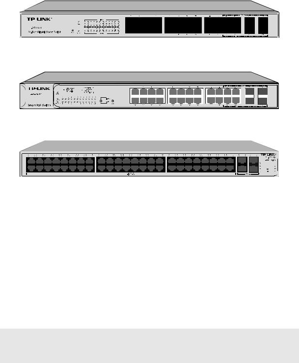
The front panel of TL-SG2424 is shown as Figure 2-3.
Figure 2-3 Front Panel of TL-SG2424
The front panel of TL-SG2424P is shown as Figure 2-4.
Figure 2-4 Front Panel of TL-SG2424P
The front panel of TL-SG2452 is shown as Figure 2-5.
Figure 2-5 Front Panel of TL-SG2452
The following parts are located on the front panel of TL-SG2216/TL-SG2424/TL-SG2424P/ TL-SG2452:
Reset: Press this button for five seconds or above to reset the software setting back to factory default setting.
10/100/1000Mbps Ports: Designed to connect to the device with a bandwidth of 10Mbps, 100Mbps or 1000Mbps. Each has a corresponding 1000Mbps LED and link/Act LED.
SFP Ports: Designed to install the SFP module. TL-SG2216/TL-SG2424/TL-SG2424P switch features some SFP transceiver slots that are shared with the associated RJ45 ports. The associated two ports are referred to as “combo” ports, which means they cannot be used simultaneously, otherwise only SFP ports work. TL-SG2452 features 4 individual SFP ports.
 Note:
Note:
The SFP port can only be used with a gigabit module.
LEDs
For TL-SG2216/TL-SG2424:
|
Name |
Status |
Indication |
|
|
On |
Power is on. |
|
Power |
|
|
|
Flashing |
Power supply is abnormal. |
|
|
|
|
|
|
|
Off |
Power is off or power supply is abnormal. |
|
|
|
|
|
|
|
8 |
|
Name |
|
Status |
|
Indication |
|
|
|
On |
|
The switch is working abnormally. |
|
System |
|
|
|
|
|
|
Flashing |
The switch is working normally. |
||
|
|
|
|
|
|
|
|
|
Off |
The switch is working abnormally. |
|
|
|
|
|
|
|
|
|
|
On |
|
A 1000Mbps device is connected to the corresponding port. |
|
1000Mbps |
|
|
|
|
|
|
Off |
|
A 10/100Mbps device or no device is connected to the |
|
|
|
|
|
corresponding port. |
|
|
|
|
|
|
|
|
|
|
|
|
|
|
|
|
On |
|
A device is connected to the corresponding port but no activity. |
|
|
|
|
|
|
|
Link/Act |
|
Flashing |
|
Data is being transmitted or received. |
|
|
|
Off |
No device is connected to the corresponding port. |
|
|
|
|
|
|
|
For TL-SG2424P:
TL-SG2424P has a LED mode switch button which is for switching the LED status indication. When the Speed LED is on, the port LED is indicating the data transmission rate. When the PoE LED is on, the port LED is indicating the power supply status. By default the Speed LED is on. Pressing the mode switch button, the Speed LED will turn off and the PoE LED will light up. Then the PoE LED will turn off after being on for 60 seconds and the Speed LED will light up again.
When the Speed LED is on, the port LED is indicating the data transmission rate.
|
Name |
|
Status |
|
Indication |
|
|
|
|
On |
|
The switch is powered on. |
|
|
Power |
|
|
|
|
|
|
|
Off |
The switch is powered off or power supply is abnormal. |
|||
|
|
|
|
|
|
|
|
|
|
Flashing |
Power supply is abnormal. |
||
|
|
|
|
|
|
|
|
System |
|
Flashing |
|
The switch works properly. |
|
|
|
|
|
|
|
|
|
|
On/Off |
The switch works improperly. |
|||
|
|
|
||||
|
|
|
|
|
|
|
|
|
|
|
On |
|
A 1000Mbps device is connected to the corresponding |
|
|
|
Green |
|
port, but no activity. |
|
|
|
|
|
|
||
|
|
|
|
Flashing |
Data is being transmitted or received. |
|
|
10/100/1000Mbps |
|
|
|
|
|
|
|
|
On |
|
A 10/100Mbps device is connected to the |
|
|
|
|
Yellow |
|
corresponding port, but no activity. |
|
|
|
|
|
|
||
|
|
|
|
Flashing |
Data is being transmitted or received. |
|
|
|
|
|
|
|
|
|
|
|
Off |
No device is connected to the corresponding port. |
||
|
|
|
|
|
|
|
When the PoE LED is on, the port LED is indicating the power supply status.
|
Name |
|
Status |
Indication |
|
|
|
On |
The switch is powered on. |
|
Power |
|
|
|
|
|
Off |
The switch is powered off or power supply is abnormal. |
|
|
|
|
|
|
|
|
|
Flashing |
Power supply is abnormal. |
|
|
|
|
|
|
System |
|
Flashing |
The switch works properly. |
|
|
|
|
|
|
|
On/Off |
The switch works improperly. |
|
|
|
|
||
|
|
|
|
|
|
|
|
|
9 |

|
Name |
|
|
Status |
|
|
|
Indication |
|
||
|
|
|
|
On |
|
|
|
The remaining PoE power≤7W. |
|
||
|
|
|
|
|
|
|
|
|
|
||
|
PoE Max |
|
|
Flashing |
The remaining PoE power keeps ≤7W after this LED is |
|
|||||
|
|
|
|
|
|
|
on for 2 minutes. |
|
|||
|
|
|
|
|
|
|
|
|
|||
|
|
|
|
|
|
|
|
|
|
|
|
|
|
|
|
Off |
|
|
The remaining PoE power≥7W. |
|
|||
|
|
|
|
|
|
|
|
|
|
|
|
|
|
|
|
|
|
|
On |
|
The port is supplying power normally. |
|
|
|
|
|
|
Green |
|
|
|
|
|
|
|
|
|
|
|
|
Flashing |
The supply power exceeds the corresponding port’s |
|
||||
|
|
|
|
|
|
|
|
||||
|
10/100/1000Mbps |
|
|
|
|
|
|
maximum power. |
|
||
|
|
|
Yellow |
|
On |
|
Overload or short circuit is detected. |
|
|||
|
|
|
|
|
|
|
|||||
|
|
|
|
|
|
|
|
|
|||
|
|
|
|
|
Flashing |
Power-on self-test has failed. |
|
||||
|
|
|
|
|
|
|
|
|
|
|
|
|
|
|
|
Off |
|
|
No PoE power supply is provided on the port. |
|
|||
|
|
|
|
|
|
|
|
|
|
|
|
For TL-SG2452: |
|
|
|
|
|
|
|
|
|
|
|
|
|
|
|
|
|
|
|
|
|
|
|
|
Name |
|
Status |
|
|
|
|
Indication |
|
||
|
|
|
|
|
|
On |
|
|
Power is on. |
|
|
|
PWR |
|
|
|
|
|
|
|
|||
|
|
|
Flashing |
|
Power supply is abnormal. |
|
|||||
|
|
|
|
|
|
|
|
|
|
||
|
|
|
|
|
|
Off |
|
Power is off or power supply is abnormal. |
|
||
|
|
|
|
|
|
|
|
|
|
|
|
|
|
|
|
|
|
On |
|
|
The switch is working abnormally. |
|
|
|
SYS |
|
|
|
|
|
|
|
|||
|
|
|
Flashing |
|
The switch is working normally. |
|
|||||
|
|
|
|
|
|
|
|
|
|
||
|
|
|
|
|
|
Off |
|
The switch is working abnormally. |
|
||
|
|
|
|
|
|
|
|
|
|
|
|
|
|
|
|
|
|
|
On |
|
|
A 1000Mbps device is connected to the corresponding |
|
|
|
|
Green |
|
|
|
|
port but no activity. |
|
||
|
|
|
|
|
|
|
|
|
|||
|
|
|
|
|
|
|
Flashing |
|
Data is being transmitted or received. |
|
|
|
|
|
|
|
|
|
|
|
|
|
|
|
10/100/1000Mbps |
|
|
|
|
|
On |
|
|
A 10/100Mbps device is connected to the corresponding |
|
|
|
Yellow |
|
|
|
|
port but no activity. |
|
|||
|
|
|
|
|
|
|
|
|
|||
|
|
|
|
|
|
|
Flashing |
|
|
Data is being transmitted or received. |
|
|
|
|
|
|
|
|
|
|
|
||
|
|
|
|
|
|
Off |
|
No device is connected to the corresponding port. |
|
||
|
|
|
|
|
|
|
|
|
|
|
|
2.3.2 Rear Panel
The rear panel of TL-SG2210P features a power socket and eight ports. Its rear panel is shown as the following figure.
Figure 2-6 Rear Panel of TL-SG2210P
10/100/1000Mbps Ports: Designed to connect to the device with a bandwidth of 10Mbps, 100Mbps or 1000Mbps. Each has a corresponding LED on the front panel.
SFP Ports: Designed to install the SFP module. The SFP port can only be used with a gigabit module.
10
Power Socket: Connect the female connector of the power cord here, and the male connector to the DC power outlet. Please make sure the voltage of the power supply meets the requirement of the input voltage (48V/1.25A).
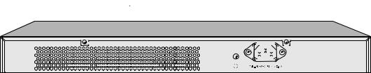
The rear panel of TL-SG2216/TL-SG2424/TL-SG2424P/TL-SG2452 features a power socket and a Grounding Terminal (marked with

 ), here we take TL-SG2424 for example.
Figure 2-7 Rear Panel of the switch
Grounding Terminal: The switch already comes with Lightning Protection Mechanism. You can also ground the switch through the PE (Protecting Earth) cable of AC cord or with Ground Cable.
AC Power Socket: Connect the female connector of the power cord here, and the male connector to the AC power outlet. Please make sure the voltage of the power supply meets the requirement of the input voltage (100-240V~ 50/60Hz 0.6A for TL-SG2216/TL-SG2424, 100-240V~ 50/60Hz 3.5A for TL-SG2424P and100-240V~ 50/60Hz 1.0A for TL-SG2452).
Return to CONTENTS
11
Chapter 3 Login to the Switch
3.1Login
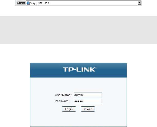
1)To access the configuration utility, open a web-browser and type in the default address http://192.168.0.1 in the address field of the browser, then press the Enter key.
Figure 3-1 Web-browser
 Tips:
Tips:
To log in to the switch, the IP address of your PC should be set in the same subnet addresses of the switch. The IP address is 192.168.0.x ("x" is any number from 2 to 254), Subnet Mask is 255.255.255.0. For the detailed instructions as to how to do this, please refer to Appendix B.
2)After a moment, a login window will appear, as shown in Figure 3-2. Enter admin for the User Name and Password, both in lower case letters. Then click the Login button or press the Enter key.
Figure 3-2 Login
3.2 Configuration
After a successful login, the main page will appear as Figure 3-3, and you can configure the function by clicking the setup menu on the left side of the screen.
12
Figure 3-3 Main Setup-Menu
 Note:
Note:
Clicking Apply can only make the new configurations effective before the switch is rebooted. If you want to keep the configurations effective even the switch is rebooted, please click Save Config. You are suggested to click Save Config before cutting off the power or rebooting the switch to avoid losing the new configurations.
Return to CONTENTS
13
Chapter 4 System
The System module is mainly for system configuration of the switch, including four submenus:
System Info, User Management, System Tools and Access Security.
4.1 System Info
The System Info, mainly for basic properties configuration, can be implemented on System Summary, Device Description, System Time, Daylight Saving Time and System IP pages.
4.1.1 System Summary
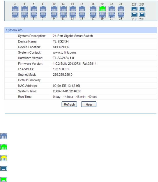
On this page you can view the port connection status and the system information.
The port status diagram shows the working status of 24 10/100/1000Mbps RJ45 ports and 4 SFP ports of the switch.
Choose the menu System→System Info→System Summary to load the following page.
Figure 4-1 System Summary
Port Status
Indicates the 1000Mbps port is not connected to a device.
Indicates the 1000Mbps port is at the speed of 1000Mbps.
Indicates the 1000Mbps port is at the speed of 10Mbps or 100Mbps.
Indicates the SFP port is not connected to a device.
Indicates the SFP port is at the speed of 1000Mbps.
14
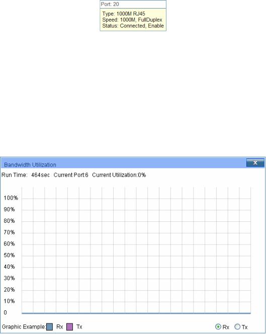
When the cursor moves on the port, the detailed information of the port will be displayed.
Figure 4-2 Port Information
Port Info
Port: |
Displays the port number of the switch. |
Type: |
Displays the type of the port. |
Rate: |
Displays the maximum transmission rate of the port. |
Status: |
Displays the connection status of the port. |
Click a port to display the bandwidth utilization on this port. The actual rate divided by theoretical maximum rate is the bandwidth utilization. The following figure displays the bandwidth utilization monitored every four seconds. Monitoring the bandwidth utilization on each port facilitates you to monitor the network traffic and analyze the network abnormities.
|
Figure 4-3 Bandwidth Utilization |
Bandwidth Utilization |
|
Rx: |
Select Rx to display the bandwidth utilization of receiving packets |
|
on this port. |
Tx: |
Select Tx to display the bandwidth utilization of sending packets |
|
on this port. |
4.1.2 Device Description
On this page you can configure the description of the switch, including device name, device location and system contact.
Choose the menu System→System Info→Device Description to load the following page.
15
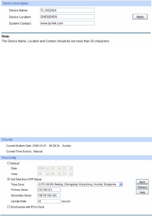
Figure 4-4 Device Description
The following entries are displayed on this screen:
Device Description
Device Name: Enter the name of the switch. Device Location: Enter the location of the switch. System Contact: Enter your contact information.
4.1.3 System Time
System Time is the time displayed while the switch is running. On this page you can configure the system time and the settings here will be used for other time-based functions.
You can manually set the system time or synchronize with PC’s clock as the system time. Choose the menu System→System Info→System Time to load the following page.
Figure 4-5 System Time
The following entries are displayed on this screen:
Time Info
Current System Date: Displays the current date and time of the switch.
Current Time Source: Displays the current time source of the switch.
16
Time Config
Manual: When this option is selected, you can set the date and time
manually.
Get Time from NTP |
When this option is selected, you can configure the time zone |
|
Server: |
|
and the IP Address for the NTP Server. The switch will get UTC |
|
|
automatically if it has connected to an NTP Server. |
|
|
Time Zone: Select your local time. |
|
|
Primary/Secondary Server: Enter the IP Address for the |
|
|
NTP Server. |
|
|
Update Rate: Specify the rate fetching time from NTP server. |
Synchronize |
with |
When this option is selected, the administrator PC’s clock is |
PC’S Clock: |
|
utilized. |

 Note:
Note:
1.The system time will be restored to the default when the switch is restarted and you need to reconfigure the system time of the switch.
2.When Get Time from NTP Server is selected and no time server is configured, the switch will get time from the time server of the Internet if it has connected to the Internet.
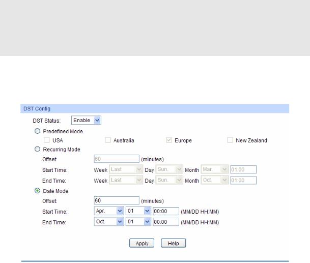
4.1.4 Daylight Saving Time
Here you can configure the Daylight Saving Time of the switch.
Choose the menu System→System Info→Daylight Saving Time to load the following page.
Figure 4-6 Daylight Saving Time
The following entries are displayed on this screen:
DST Config
DST Status: |
Enable or disable the DST. |
17
Predefined Mode: Select a predefined DST configuration.
USA: Second Sunday in March, 02:00 ~ First Sunday in November, 02:00.
Australia: First Sunday in October, 02:00 ~ First Sunday in April, 03:00.
Europe: Last Sunday in March, 01:00 ~ Last Sunday in October, 01:00.
New Zealand: Last Sunday in September, 02:00 ~ First Sunday in April, 03:00.
Recurring Mode: Specify the DST configuration in recurring mode. This configuration is recurring in use.
Offset: Specify the time adding in minutes when Daylight Saving Time comes.
Start/End Time: Select starting time and ending time of Daylight Saving Time.
Date Mode: Specify the DST configuration in Date mode. This configuration is recurring in use.
Offset: Specify the time adding in minutes when Daylight Saving Time comes.
Start/End Time: Select starting time and ending time of Daylight Saving Time.
 Note:
Note:
1.When the DST is disabled, the predefined mode, recurring mode and date mode cannot be configured.
2.When the DST is enabled, the default daylight saving time is of European in predefined mode.
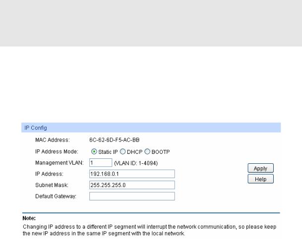
4.1.5 System IP
Each device in the network possesses a unique IP Address. You can log on to the Web management page to operate the switch using this IP Address. The switch supports three modes to obtain an IP address: Static IP, DHCP and BOOTP. The IP address obtained using a new mode will replace the original IP address. On this page you can configure the system IP of the switch.
Choose the menu System→System Info→System IP to load the following page.
Figure 4-7 System IP
18

The following entries are displayed on this screen:
IP Config
MAC Address: Displays MAC Address of the switch.
IP Address Mode: Select the mode to obtain IP Address for the switch.
Static IP: When this option is selected, you should enter IP Address, Subnet Mask and Default Gateway manually.
DHCP: When this option is selected, the switch will obtain network parameters from the DHCP Server.
BOOTP: When this option is selected, the switch will obtain network parameters from the BOOTP Server.
Management VLAN: Enter the ID of management VLAN, the only VLAN through which you can get access to the switch. By default VLAN1 owning all the ports is the Management VLAN and you can access the switch via any port on the switch. However, if another VLAN is created and set to be the Management VLAN, you may have to reconnect the management station to a port that is a member of the Management VLAN.
IP Address: Enter the system IP of the switch. The default system IP is 192.168.0.1 and you can change it appropriate to your needs.
Subnet Mask: Enter the subnet mask of the switch.
Default Gateway: Enter the default gateway of the switch.

 Note:
Note:
1.Changing the IP address to a different IP segment will interrupt the network communication, so please keep the new IP address in the same IP segment with the local network.
2.The switch only possesses one IP address. The IP address configured will replace the original IP address.
3.If the switch gets the IP address from DHCP server, you can see the configuration of the switch in the DHCP server; if DHCP option is selected but no DHCP server exists in the network, a few minutes later, the switch will restore the setting to the default.
4.If DHCP or BOOTP option is selected, the switch will get network parameters dynamically from the Internet, which means that IP address, subnet mask and default gateway can not be configured.
5.By default, the IP address is 192.168.0.1.
4.2 User Management
User Management functions to configure the user name and password for users to log on to the Web management page with a certain access level so as to protect the settings of the switch from being randomly changed.
The User Management function can be implemented on User Table and User Config pages.
4.2.1 User Table
On this page you can view the information about the current users of the switch. Choose the menu System→User Management→User Table to load the following page.
19
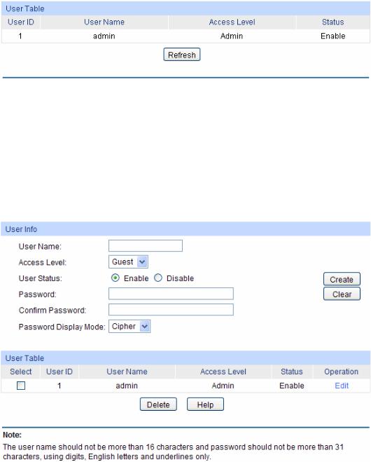
Figure 4-8 User Table
4.2.2 User Config
On this page you can configure the access level of the user to log on to the Web management page. The switch provides two access levels: Guest and Admin. The guest only can view the settings without the right to configure the switch; the admin can configure all the functions of the switch. The Web management pages contained in this guide are subject to the admin’s login without any explanation.
Choose the menu System→User Management→User Config to load the following page.
Figure 4-9 User Config
The following entries are displayed on this screen:
User Info
User Name: Create a name for users’ login.
Access Level: Select the access level to login.
Admin: Admin can edit, modify and view all the settings of different functions.
Guest: Guest only can view the settings without the right to edit and modify.
User Status: Select Enable/Disable the user configuration.
Password: |
Type a password for users’ login. |
20
Confirm Password:
Password Display
Mode:
Retype the password.
Simple: Select a simple password display mode.
Cipher: Select a cipher password display mode.
User Table
Select: Select the desired entry to delete the corresponding user
User ID, Name, Access Level and status:
Operation:
information. It is multi-optional. The current user information can’t be deleted.
Displays the current user ID, user name, access level and user status.
Click the Edit button of the desired entry, and you can edit the corresponding user information. After modifying the settings, please click the Modify button to make the modification effective. Access level and user status of the current user information cannot be modified.
4.3 System Tools
The System Tools function, allowing you to manage the configuration file of the switch, can be implemented on Config Restore, Config Backup, Firmware Upgrade, System Reboot and System Reset pages.
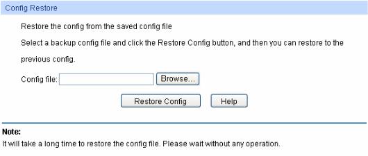
4.3.1 Config Restore
On this page you can upload a backup configuration file to restore your switch to this previous configuration.
Choose the menu System→System Tools→Config Restore to load the following page.
Figure 4-10 Config Restore
The following entries are displayed on this screen:
Config Restore
Restore Config: Click the Restore Config button to restore the backup
configuration file. It will take effect after the switch automatically reboots.
21
 Note:
Note:
1.It will take a few minutes to restore the configuration. Please wait without any operation.
2.To avoid any damage, please don’t power down the switch while being restored.
3.After being restored, the current settings of the switch will be lost. Wrong uploaded configuration file may cause the switch unmanaged.
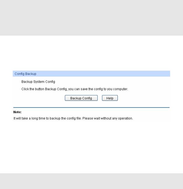
4.3.2 Config Backup
On this page you can download the current configuration and save it as a file to your computer for your future configuration restore.
Choose the menu System→System Tools→Config Backup to load the following page.
Figure 4-11 Config Backup
The following entries are displayed on this screen:
Config Backup
Backup Config: Click the Backup Config button to save the current configuration
as a file to your computer. You are suggested to take this measure before upgrading.

 Note:
Note:
It will take a few minutes to backup the configuration. Please wait without any operation.
4.3.3 Firmware Upgrade
The switch system can be upgraded via the Web management page. To upgrade the system is to get more functions and better performance. Go to http://www.tp-link.com to download the updated firmware.
Choose the menu System→System Tools→Firmware Upgrade to load the following page.
22
 Loading...