


Enterprise Networking Solution
User Guide
Gigabit Uplink Web Smart Switch
TL-SL2210WEB/TL-SL2218WEB TL-SL2428WEB/TL-SL2452WEB


COPYRIGHT & TRADEMARKS
Specifications are subject to change without notice.  is a registered trademark of TP-LINK TECHNOLOGIES CO., LTD. Other brands and product names are trademarks of their respective holders.
No part of the specifications may be reproduced in any form or by any means or used to make any derivative such as translation, transformation, or adaptation without permission from TP-LINK TECHNOLOGIES CO., LTD. Copyright © 2012 TP-LINK TECHNOLOGIES CO., LTD. All rights reserved.
http://www.tp-link.com
FCC STATEMENT
This equipment has been tested and found to comply with the limits for a Class A digital device, pursuant to part 15 of the FCC Rules. These limits are designed to provide reasonable protection against harmful interference when the equipment is operated in a commercial environment. This equipment generates, uses, and can radiate radio frequency energy and, if not installed and used in accordance with the instruction manual, may cause harmful interference to radio communications. Operation of this equipment in a residential area is likely to cause harmful interference in which case the user will be required to correct the interference at his own expense.
This device complies with part 15 of the FCC Rules. Operation is subject to the following two conditions:
111 This device may not cause harmful interference.
222This device must accept any interference received, including interference that may cause undesired operation.
Any changes or modifications not expressly approved by the party responsible for compliance could void the user’s authority to operate the equipment.
CE Mark Warning
This is a Class A product. In a domestic environment, this product may cause radio interference, in which case the user may be required to take adequate measures.
Copyright & Trademarks |
|
I |
|
||
|

Related Document
This User Guide is also available in PDF on our website. To obtain the latest product information, please visit the official website:
http://www.tp-link.com
About this User Guide
This User Guide describes the hardware characteristics, installation methods and the points that should be attended to during installation. This User Guide is structured as follows:
Chapter 1 Introduction. This chapter describes the external components of the Switch.
Chapter 2 Installation. This chapter illustrates how to install the Switch.
Chapter 3 Lightning Protection. This chapter illustrates how to prevent lightning damage.
Chapter 4 Connection. This chapter illustrates how to do the physical connection of the Switch.
Chapter 5 Function Description. This chapter describes the functions supported by the switch family and presents the network concepts referred in this Guide.
Chapter 6 Web Management. This chapter gives an explanation to the terms in WEB interface and describes the configuring suggestions of the Switch.
Appendix A Troubleshooting. Appendix B Table of Factory Defaults.
Appendix C Table of Funtion Differences of Switch Family. Appendix D Hardware Specifications.
Appendix E Technical Support.
II |
|
Related Document |
|
||
|
Audience
This User Guide is for:
Network Engineer
Network Administrator
Conventions
Due to the similarity in structure of TL-SL2210WEB/TL-SL2218WEB/TL-SL2428WEB/ TL-SL2452WEB Gigabit Uplink Web Smart Switch series, in this User Guide we take TL-SL2210WEB as an example to illustrate Chapter 2 Installation, Chapter 3 Lightning Protection, Chapter 4 Connection and Chapter 6 WEB Management.
This Guide uses the specific formats to highlight special messages. The following table lists the notice icons that are used throughout this guide.
Remind to be careful. A caution indicates a potential which may result in device damage.
Remind to take notice. The note contains the helpful information for a better use of the product.
Remind to get further information. The further information provides you more details about the product.
Audience  III
III

Contents
Chapter 1 |
Introduction |
——————————————— |
01 |
1.1 |
Product Overview............................................................................................ |
01 |
|
1.2 |
Features............................................................................................................... |
|
01 |
1.3 |
Appearance........................................................................................................ |
|
02 |
Chapter 2 |
Installation ———————————————— |
05 |
|
2.1 |
Package Contents ............................................................................................ |
05 |
|
2.2 |
Safety Precautions ........................................................................................... |
05 |
|
2.3 |
Installation Tools............................................................................................... |
|
08 |
2.4 |
Product Installation......................................................................................... |
08 |
|
Chapter 3 Lightning Protection ———————————— |
10 |
||
3.1 |
Cabling Reasonably......................................................................................... |
10 |
|
3.2 |
Connect to Ground.......................................................................................... |
12 |
|
Chapter 4 |
Connection |
——————————————— |
13 |
4.1 |
Ethernet Port ..................................................................................................... |
|
13 |
4.2 |
SFP Port ............................................................................................................... |
|
13 |
4.3 |
Verify Installation |
............................................................................................. |
14 |
4.4 |
Power On............................................................................................................. |
|
14 |
Chapter 5 Function Description———————————— |
15 |
||
5.1 |
System Setting.................................................................................................. |
|
15 |
5.1.1 |
System Setting.......................................................................................... |
15 |
|
5.1.2 |
File Transfer ................................................................................................ |
|
15 |
5.1.3 |
Reboot & Reset.......................................................................................... |
15 |
|
5.1.4 |
User ............................................................................................................... |
|
15 |
5.2 |
Port Setting ........................................................................................................ |
|
15 |
5.2.1 |
Port Parameter.......................................................................................... |
15 |
|
5.2.2 |
Port Statistic and Port Status ............................................................... |
16 |
|
5.2.3 |
Storm Control............................................................................................ |
16 |
|
5.2.4 |
Port Description ....................................................................................... |
16 |
|
5.3 |
Network Setting ............................................................................................... |
|
17 |
5.3.1 |
Network Setting ....................................................................................... |
17 |
|
5.3.2 |
Aging Time and Dynamic Address Table......................................... |
17 |
|
5.3.3 |
Static MAC Address Table...................................................................... |
18 |
|
5.3.4 |
Filtering MAC Address Table ................................................................ |
18 |
|
IV  Contents

5.3.5 |
Dynamic Binding...................................................................................... |
18 |
5.3.6 |
Ping ............................................................................................................... |
19 |
5.4 |
VLAN Setting ..................................................................................................... |
19 |
5.4.1 |
VLAN Mode ................................................................................................ |
19 |
5.5 |
Port Trunking..................................................................................................... |
20 |
5.6 |
Priority Setting.................................................................................................. |
20 |
5.6.1 |
Priority Mode............................................................................................. |
20 |
5.6.2 |
Port-Based Priority................................................................................... |
20 |
5.6.3 |
Port Default Priority ................................................................................ |
21 |
5.6.4 |
802.1p Priority........................................................................................... |
21 |
5.7 |
Port Mirroring.................................................................................................... |
21 |
5.8 |
Virtual Cable Test.............................................................................................. |
21 |
Chapter 6 WEB Management————————————— 22 |
||
6.1 |
Overview............................................................................................................. |
22 |
6.2 |
Connecting to the Device............................................................................. |
22 |
6.2.1 |
Getting Started ......................................................................................... |
22 |
6.2.2 |
Login the Switch....................................................................................... |
25 |
6.3 |
Setting the Device ........................................................................................... |
25 |
6.3.1 |
System Setting.......................................................................................... |
28 |
6.3.2 |
Port Setting ................................................................................................ |
30 |
6.3.3 |
Network Setting ....................................................................................... |
35 |
6.3.4 |
VLAN Setting.............................................................................................. |
41 |
6.3.5 |
Port Trunking............................................................................................. |
45 |
6.3.6 |
Priority Setting.......................................................................................... |
46 |
6.3.7 |
Port Mirroring............................................................................................ |
48 |
6.3.8 |
Virtual Cable Test...................................................................................... |
49 |
Appendix A Troubleshooting ————————————— 50 Appendix B Table of Factory Defaults —————————— 51 Appendix C Table of Function Di erences of Switch Family — 53 Appendix D Hardware Speci cations —————————— 54 Appendix E Technical Support ————————————— 55
Contents  V
V

Gigabit Uplink Web Smart Switch
CCCCCCCCCC Introduction
1111 Product Overview
The TL-SL2210WEB/TL-SL2218WEB/TL-SL2428WEB/TL-SL2452WEB Gigabit Uplink Web Smart Switch is compliant with the IEEE802.3 Ethernet protocols. The EIA-standardized framework and smart configuration capacity can provide flexible solutions for variable scale of networks.
This switch family is equipped with powerful management interface, via which system, port, network, VLAN, truck and priority can be configured.
The TL-SL2210WEB/TL-SL2218WEB/TL-SL2428WEB/TLSL2452WEB Gigabit Uplink Web Smart Switch provides 8/16/24/48 10/100Mbps Fast Ethernet ports, 1/1/2/2 10/100/1000Mbps Gigabit Ethernet ports and 1/1/2/2 SFP ports respectively, which extends the connecting area and increases the networking flexibility.
1111 Features
¾¾ Compliant with IEEE802.3, IEEE802.3u, IEEE802.3ab and IEEE802.3z Standards ¾¾ IEEE 802.3x flow control for full-duplex
¾¾ Back pressure flow control for half-duplex ¾¾ Store-and-Forward switching method
¾¾ Support N-Way adaptive mode
¾¾ Support up 200 meters of Cat. 5 cables at the transmission speed of 10Mbps ¾¾ Support MAC address table of 8K entries
¾¾ Support MAC address learning and aging time
¾¾ Support port-based VLAN and IEEE802.1Q tag VLAN ¾¾ Support trunks
¾¾ Support management via WEB browser
¾¾ Support port-based priority and IEEE 802.1p priority ¾¾ Support static MAC address and filtering MAC address ¾¾ Support dynamic binding of MAC address
¾¾ Support port security, storm control and port monitoring ¾¾ Support virtual cable test
¾¾ Support static switch IP address and dynamic switch IP address through DHCP client ¾¾ Support system upgrading, configuration uploading and backup through TFTP server
01 |
|
Introduction |
|
||
|

Gigabit Uplink Web Smart Switch
1111 Appearance
■■ Front Panel
The front panel of TL-SL2210WEB is shown as the following figure.
|
|
|
|
|
R |
TL-SL2210WEB |
8+2G Web-Smart Switch |
|
|
|
|
|
|
|
||||||
|
|
|
|
|
|
|
|
|
|
|
1 |
2 |
3 |
4 |
5 |
6 |
7 |
8 |
GIGA |
SFP |
Power |
Link |
|
|
|
|
|
|
|
|
Link/Act |
|
|
|
|
|
|
|
|
|
|
|
Act |
1 |
2 |
3 |
4 |
5 |
6 |
7 |
8 |
|
|
|
|
|
|
|
|
|
|
|
System |
100M |
|
|
|
|
|
|
|
|
1000M |
|
|
|
|
|
|
|
|
|
Link/Act |
|
|
|
|
|
|
|
|
|
GIGA |
RESET |
|
|
|
10/100Mbps |
|
|
|
10/100/1000Mbps |
1000Mbps |
|
LEDs
RESET
10/100Mbps RJ45 Port
10/100/1000Mbps RJ45 Port
SFP Port
FFFFFFFFFFF Front Panel of TL-SL2210WEB
The front panel of TL-SL2218WEB is shown as the following figure.
|
|
|
|
|
|
|
|
|
1 |
3 |
5 |
7 |
9 |
11 |
13 |
15 |
TL-SL2218WEB |
|
|
|
|
|
|
|
|
Link |
|
|
|
|
|
|
GIGA |
1 |
3 |
5 |
7 |
9 |
11 |
13 |
15 |
Act |
|
|
|
|
|
|
||
|
|
|
|
|
|
|
|
100Mbps |
|
|
|
|
|
|
SFP |
|
|
|
|
|
|
|
|
|
|
RESET |
|
|
|
|
|
|
|
|
Power |
|
|
|
|
|
|
|
Link/Act |
|
|
|
|
|
|
|
16+2G Gigabit Web-Smart Switch |
2 |
4 |
6 |
8 |
10 |
12 |
14 |
16 |
|
|
|
|
|
|
|
Link/Act |
System |
|
|
|
|
|
|
|
1000Mbps |
|
|
|
10 |
12 |
14 |
16 |
|
|
|
|
|
|
|
|
|
|
2 |
4 |
6 |
8 |
LEDs
RESET
10/100Mbps RJ45 Port
10/100/1000Mbps RJ45 Port
SFP Port
FFFFFFFFFFF Front Panel of TL-SL2218WEB
The front panel of TL-SL2428WEB is shown as the following figure.
TL-SL2428WEB |
|
24+4G Gigabit Web-Smart Switch |
Reset |
|
LEDs
10/100Mbps RJ45 Port
10/100/1000Mbps RJ45 Port
SFP Port
Reset
FFFFFFFFFFF Front Panel of TL-SL2428WEB
The front panel of TL-SL2452WEB is shown as the following figure.
|
TL-SL2452WEB |
Power |
48+4G Gigabit Web-Smart Switch |
RESET |
|
System |
|
RESET
LEDs
10/100Mbps RJ45 Port
10/100/1000Mbps RJ45 Port
SFP Port
FFFFFFFFFFF Front Panel of TL-SL2452WEB
Introduction  02
02

Gigabit Uplink Web Smart Switch
RESET
Press this button for three seconds to reset the software setting back to factory default setting.
LEDs
LED |
Status |
Indication |
|
|
|
|
|
Power |
On |
The Switch is powered on |
|
|
|
||
Off |
The Switch is powered off or power supply is abnormal |
||
|
|||
|
|
|
|
System |
On |
The Switch works properly |
|
|
|
||
Off |
The Switch works improperly |
||
|
|||
|
|
|
|
|
On |
A valid link is established on the port |
|
|
|
|
|
Link/Act |
Flashing |
Data is being transmitted or received. (SFP port has Link/ |
|
Act LED only and must connect to 1000Mbps device.1 |
|||
|
|
||
|
|
|
|
|
Off |
No device is connected to the corresponding port |
|
|
|
|
|
|
On |
The corresponding port is running at 100Mbps |
|
|
|
|
|
100Mbps |
Off |
There is no device linked to the corresponding port or the |
|
port is running at 10Mbps |
|||
|
|
||
|
|
|
|
|
On |
The corresponding port is running at 1000Mbps |
|
1000Mbps |
|
|
|
Off |
There is no device linked to the corresponding port or the |
||
|
port is running at 100Mbps |
||
|
|
||
|
|
|
Port Feature
Model |
10/100Mbps RJ45 Port |
10/100/1000Mbps RJ45 Port |
SFP Port |
|
|
|
|
TL-SL2210WEB |
8 |
1 |
1 |
|
|
|
|
TL-SL2218WEB |
16 |
1 |
1 |
|
|
|
|
TL-SL2428WEB |
24 |
2 |
2 |
|
|
|
|
TL-SL2452WEB |
48 |
2 |
2 |
|
|
|
|
10/100Mbps RJ45 Port
Designed to connect to the device with the bandwidth of 10Mbps or 100Mbps. Each port has a corresponding Link/Act and 100Mbps LED.
10/100/1000Mbps RJ45 Port
Designed to connect to the device with the bandwidth of 10Mbps, 100Mbps or 1000Mbps. It has a corresponding Link/Act and 1000Mbps LED.
SFP Port
Designed to install SFP module. It has a corresponding Link/Act LED.
03 |
|
Introduction |
|
||
|
Gigabit Uplink Web Smart Switch
■■ Rear Panel
The rear panel of TL-SL2210WEB/TL-SL2218WEB/TL-SL2428WEB/TL-SL2452WEB is shown as the following figure.
Power Socket
FFFFFFFFFFF Rear Panel
Power Socket
Connect the female connector of the power cord here, and the male connector to the AC power outlet. Please make sure the voltage of the power supply meets the requirement of the input voltage.
Caution: Please use the provided power cord.
Introduction  04
04
Gigabit Uplink Web Smart Switch
CCCCCCCCCCInstallation
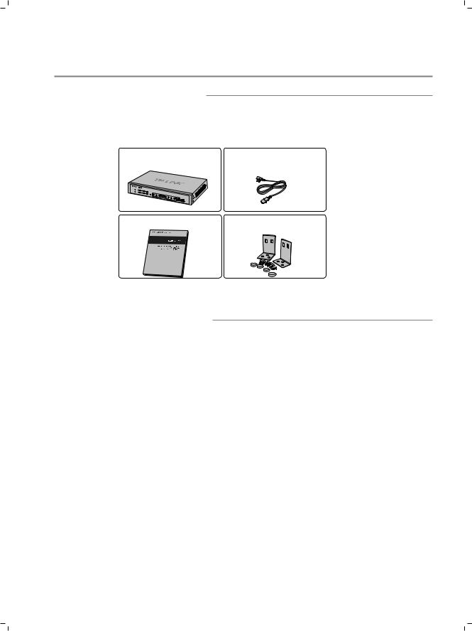
2222 Package Contents
Make sure that the package contains the following items. If any of the listed items is damaged or missing, please contact your distributor.
One Gigabit Uplink Web Smart One AC Power Cord
Switch
TL- |
SL2210WEB |
This User Guide |
Two Mounting Brackets and the |
|
Fittings |
2222 Safety Precautions
To avoid any device damage and bodily injury caused by improper use, please observe the following rules.
■■ Safety Precautions
■■ Keep the power off during the installation.
■■ Wear an ESD-preventive wrist strap, and make sure that the wrist strap has a good skin contact and is well grounded.
■■ Use only the power cord provided with the Switch.
■■ Make sure that the supply voltage matches the specifications indicated on the rear panel of the Switch.
■■ |
Ensure the vent hole is well ventilated and unblocked. |
■■ |
Do not open or remove the cover of the Switch. |
■■ |
Before cleaning the device, cut off the power supply. Do not clean it by the waterish |
|
cloth, and never use any other liquid cleaning method. |
05  Installation
Gigabit Uplink Web Smart Switch
■■ Site Requirements
To ensure normal eperation and long service life of the device, please install it in an environment that meets the requirements described in the following subsection.
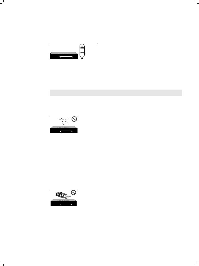
Temperature/Humidity
TL-SL2210WEB
Please keep a proper temperature and humidity in the equipment room. Too high/low humidity may lead to bad insulation, electricity leakage, mechanical property changes and corrosions. Too high temperature may accelerate aging of the insulation materials and can thus significantly shorten the service life of the device. For normal temperature and humidity of the device, please check the following table.
Environment |
Temperature |
Humidity |
|
|
|
Operating |
0 ~ 40 |
10% ~ 90%RH Non-condensing |
|
|
|
Storage |
-40 ~ 70 |
5% ~ 90%RH Non-condensing |
|
|
|
Clearness
TL-SL2210WEB
The dust accumulated on the Switch can be absorbed by static electricity and result in poor contact of metal contact points. Some measures have been taken for the device to prevent static electricity, but too strong static electricity can cause deadly damage to the electronic elements on the internal circuit board. To avoid the effect of static electricity on the operation of the Switch, please attach much importance to the following items:
■■
■■
Dust the device regularly, and keep the indoor air clean.
Keep the device well grounded and ensure static electricity has been transferred.
Electromagnetic Interference
TL-SL2210WEB
Electronic elements including capacitance and inductance on the device can be affected by external interferences, such as conducted emission by capacitance coupling, inductance coupling, and impedance coupling. To decrease the interferences, please make sure to take the following measures:
■■ Use the power supply that can effectively filter interference from the power grid.
Installation  06
06
Gigabit Uplink Web Smart Switch
■■
■■
Keep the device far from high-frequency, strong-current devices, such as radio transmitting station.
Use electromagnetic shielding when necessary.
Lightening Protection
TL-SL2210WEB
Extremely high voltage currents can be produced instantly when lightning occurs and the air in the electric discharge path can be instantly heated up to 20,000 . As this instant current is strong enough to damage electronic devices, more effective lightning protection measures should be taken.
■■
■■
■■
■■
Ensure the rack and device are well earthed.
Make sure the power socket has a good contact with the ground. Keep a reasonable cabling system and avoid induced lightning. Use the signal SPD (Surge Protective Device\ when wiring outdoor.
Note: For detailed lightning protection measures, please refer to Chapter 3 Lightning Protection.
Installation Site
 S
S
TL-SL2210WEB
When installing the device on a rack or a flat workbench, please note the following items:
■■
■■
■■
The rack or workbench is flat and stable, and sturdy enough to support the weight of 5.5kg at least.
The rack or workbench has a good ventilation system. The equipment room is well ventilated.
The rack is well grounded. Keep the power socket less than 1.5 meters away from the device.
07  Installation
Gigabit Uplink Web Smart Switch
2222 Installation Tools
■■
■■
■■
Phillips screwdriver ESD-preventive wrist wrap Cables
Note: These tools are not provided with our product. If needed, please self purchase them.
2222 Product Installation
■■ Desktop Installation
To install the device on the desktop, please follow the steps:
111Set the device on a flat surface strong enough to support the entire weight of the device with all fittings.
222Remove the adhesive backing papers from the rubber feet.
333Turnover the device and attach the supplied rubber feet to the recessed areas on the bottom at each corner of the device.
ct/ALink
bpsM 1000 |
10/100/1000Mbps |
FPS |
GAGI |
|
chtwiS tSmar-Web
1 8+2G
TRESE |
GIGA |
|
1000M |
|
|
Act k/Lin |
8 |
7 6 5 |
SL2210WEB-TL |
||
4 |
3 |
2 |
1 |
100M |
mteysS |
Act |
|
nk Li |
erPow |
Feet
Bottom of the Device
Notch
FFFFFFFFFFF Desktop Installation
■■ Rack Installation
To install the device in an EIA standard-sized, 19-inch rack, follow the instructions described below:
111Check the grounding and stability of the rack.
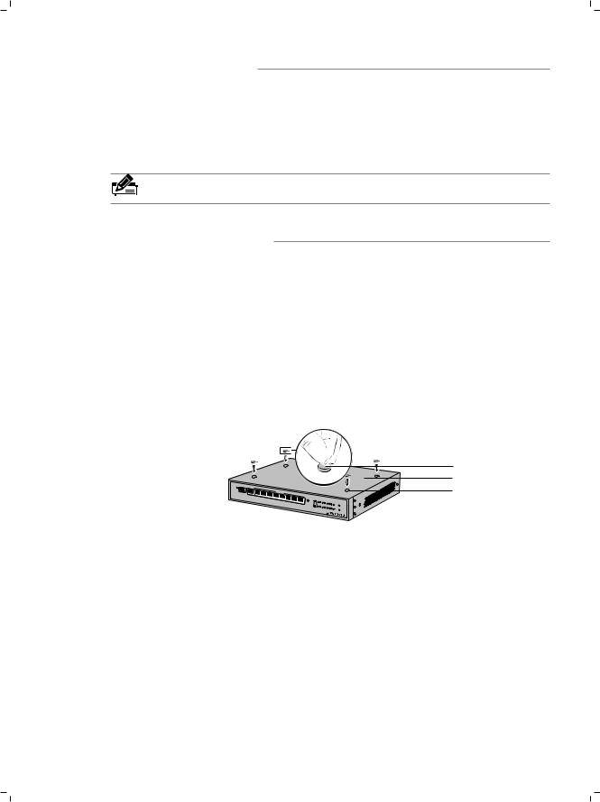
222Secure the supplied rack-mounting brackets to each side of the device with supplied screws, as illustrated in the following figure.
Installation  08
08

Gigabit Uplink Web Smart Switch
Rack-mounting Bracket
Screw
TL- |
|
SL2210WEB |
8+2G Web- |
|
Smart Switch |
GIGA |
SFP |
FFFFFFFFFFF Bracket Installation
333After the brackets are attached to the device, use suitable screws (not provided\ to secure the brackets to the rack, as illustrated in the following figure.
TL- |
|
Rack |
SL2210WEB |
8+2G Web- |
|
|
Smart Switch |
FFFFFFFFFFF Rack Installation
Caution:
■■ Please set 5~10cm gaps around the device for air circulation. ■■ Please avoid any heavy thing placed on the device.
■■ Please mount devices in sequence from the bottom to top of the rack and ensure a certain clearance between devices for the purpose of heat dissipation.
09  Installation
Gigabit Uplink Web Smart Switch
CCCCCCCCCCLightning Protection
3333 Cabling Reasonably
In the actual network environment, you may need cable outdoors and indoors, and the requirements for cabling outdoors and indoors are different. A reasonable cabling system can decrease the damage of induced lightning to devices.
Note: It's not recommended using Ethernet cables outdoors. When cabling outdoors, please use a signal lightning arrester.
■■ Requirements for Cabling Outdoors
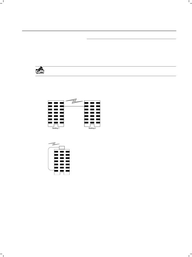
■■ Aerial cabling without safeguard is not allowed.
■■ It’s not allowed cabling down the building to connect network devices in different floors.
■■ Outdoor cables should be buried and paved to the indoor through basement. A piece of steel wire should be paved underground along the pipe and connected to the lightning protection terminal of the building for shielding. Before connecting the cable to the device, install a signal lightning arrester on the corresponding port.
■■ When an aerial cable is set up, the cable should be through a metal pipe (15m long at least\ before coming into the building. The two ends of this metal pipe should be grounded. Before connecting the cable to the device, install a signal lightning arrester on the corresponding port.
■■ It’s not necessary to pave STP cables through pipes. The shielded layer of STP cable should be well grounded. Before connecting the cable to the device, install a signal lightning arrester on the corresponding port.
Lightning Protection |
|
10 |
|
||
|
Gigabit Uplink Web Smart Switch
■■ Requirements for Cabling Indoors
When cabling indoors, keep a certain distance away from the devices that may cause high-frequency interferences, such as down-conductor cable, powerline, power transformer and electromotor.
■■
■■
The main cable should be paved in the metal raceway of the access shaft. When cabling, keep the loop area formed by the cable itself as small as possible.
Requirements for the distance between Ethernet cable and other pipelines are shown in the table.
|
Ethernet Cable |
|
Other Pipelines |
|
|
Min Parallel Net Length L |
Min Parallel-overlapping |
|
|
(mm1 |
Net Height H (mm1 |
|
|
|
Down-conductor |
1000 |
300 |
|
|
|
PE |
50 |
20 |
|
|
|
Service pipe |
150 |
20 |
|
|
|
Compressed air pipe |
150 |
20 |
|
|
|
Thermal pipe (not wrapped1 |
500 |
500 |
|
|
|
Thermal pipe (wrapped1 |
300 |
300 |
|
|
|
Gas pipe |
300 |
20 |
|
|
|
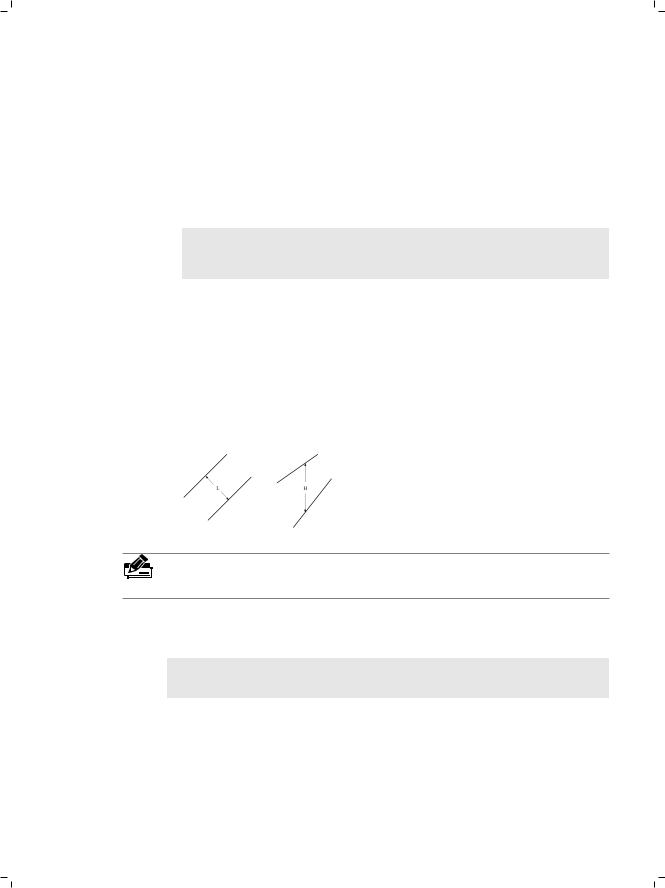
The two diagrams below demonstrate parallel net length and parallel-overlapping net height.
Note: The above minimum net length/height is required when metal raceway is not used. If any requirements cannot be met, you can add a steel tube or metal raceway for shielding.
■■ Requirements for the distance between Ethernet cable and high-power electric devices are in following tables.
|
|
Min Parallel |
|
Cable |
Pave Way |
Length |
|
|
|
(mm1 |
|
|
|
|
|
<2kVA |
Parallel cabling |
130 |
|
|
|
||
One is in the grounded metal raceway or metal pipe |
70 |
||
powerline |
|||
|
|
||
|
The both are in the grounded metal raceway or metal pipe |
10 |
|
|
|
|
11  Lightning Protection
Gigabit Uplink Web Smart Switch
2~5kVA |
|
Parallel cabling |
300 |
||
|
|
|
|
|
|
|
One is in the grounded metal raceway or metal pipe |
150 |
|||
powerline |
|
||||
|
|
|
|
|
|
|
The both are in the grounded metal raceway or metal pipe |
80 |
|||
|
|
||||
|
|
|
|
|
|
>5kVA |
|
Parallel cabling |
600 |
||
|
|
|
|
|
|
|
One is in the grounded metal raceway or metal pipe |
300 |
|||
powerline |
|
||||
|
|
|
|
|
|
|
The both are in the grounded metal raceway or metal pipe |
150 |
|||
|
|
||||
|
|
|
|
|
|
|
|
|
|
|
|
Device |
|
Min Distance (m1 |
|
|
|
|
|
|
|
|
|
Switch case |
|
1.00 |
|
|
|
|
|
|
|
||
Transformer room |
2.00 |
|
|
||
|
|
|
|
||
Elevator tower |
2.00 |
|
|
||
|
|
|
|
||
Air-conditioner room |
2.00 |
|
|
||
|
|
|
|
|
|
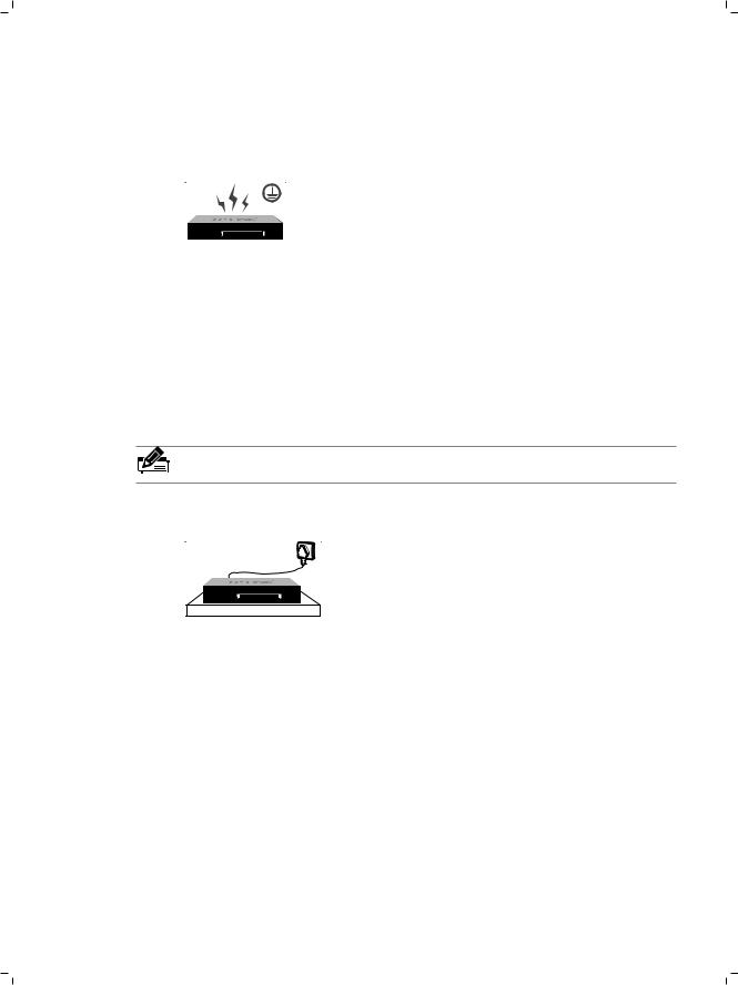
3.2 Connect to Ground
Connecting the device to ground is to quickly release the lightning over-voltage and over-current of the device, which is also a necessary measure to protect the body from electric shock.
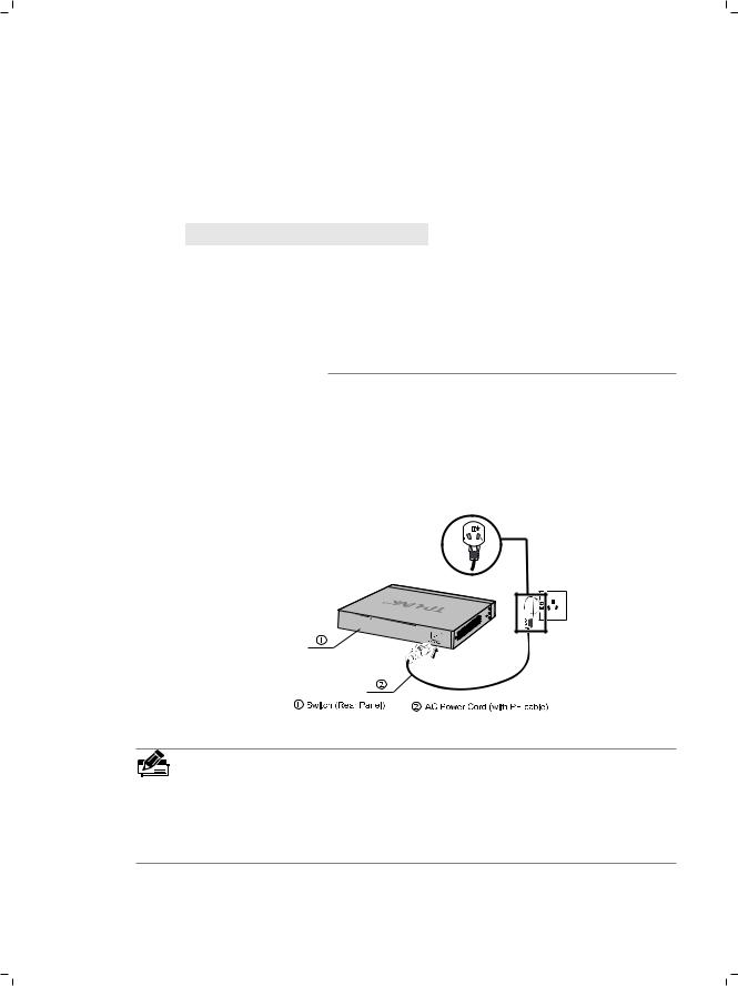
In different environments, the device may be grounded differently. If the device is installed in the normal environment, the device can be grounded via the PE (Protecting Earth\ cable of the AC power supply as shown in the following figure.
FFFFFFFFFFF Connecting to the Ground
Note:
■■ The figure is to illustrate the application and principle. The power plug you get from the package and the socket in your situation will comply with the regulation in your country, so they may differ from the figure above.
■■ If you intend to connect the device to the ground via the PE (Protecting Earth\ cable of AC power cord, please make sure the PE (Protecting Earth\ cable in the electrical outlet is well grounded in advance.
Lightning Protection |
|
12 |
|
||
|

Gigabit Uplink Web Smart Switch
CCCCCCCCCCConnection
4444 Ethernet Port
Please connect the Ethernet port of the Switch to the network devices by RJ45 cables as the following figure shown.
RJ45 Cable
RJ45 Port
TL
Smart Switch
FFFFFFFFFFF Connecting the RJ45 Port
4444 SFP Port
Connect the SFP port to a SFP module. If an SFP transceiver(purchased separately\ is installed in a slot and has a valid link on the port, the associated RJ45 port will be disabled and cannot be used.
GIGA |
SFP |
|
|
10/100/1000Mbps |
Link/Act |
|
|
|
|
R |
|
|
|
|
|
|
|
|
|
|
Power |
Act |
|
|
|
TL- |
SL2210WEB |
|
|
|
|
||||
|
Link |
|
|
|
|
|
|
|
|
|
8+2G |
|
|
|
System |
1 |
2 |
3 |
4 |
|
|
|
|
|
|
Web- |
Smart |
|
|
100M |
|
5 |
6 |
7 |
|
|
Link/Act |
1 |
Switch |
|||||
|
|
|
|
|
|
|
8 |
|
|
|
||||
|
|
|
|
|
|
|
|
|
|
1000M |
|
|
|
|
|
|
|
|
|
|
|
|
|
GIGA |
RESET |
|
|
|
|
|
|
|
|
|
|
|
|
|
|
|
|
|
|
|
GIGA
SFP
SFP Port
SFP Module
Link/Act
FFFFFFFFFFF Inserting the SFP Module
Note: SFP module supports hot-plugging, plug the SFP module into the SFP port and the switch can identify it automatically. The SFP port must connect to 1000Mbps device.
13  Connection
 Loading...