


 Loading...
User Guide
Jetstream Gigabit L2 Managed Switch
T2500G-10TS (TL-SG3210)
REV1.0.0
1910011848

COPYRIGHT & TRADEMARKS
Specifications are subject to change without notice.  is a registered trademark of TP-LINK TECHNOLOGIES CO., LTD. Other brands and product names are trademarks or registered trademarks of their respective holders.
No part of the specifications may be reproduced in any form or by any means or used to make any derivative such as translation, transformation, or adaptation without permission from TP-LINK TECHNOLOGIES CO., LTD. Copyright © 2016 TP-LINK TECHNOLOGIES CO., LTD. All rights reserved.
http://www.tp-link.com
FCC STATEMENT
This equipment has been tested and found to comply with the limits for a Class A digital device, pursuant to part 15 of the FCC Rules. These limits are designed to provide reasonable protection against harmful interference when the equipment is operated in a commercial environment. This equipment generates, uses, and can radiate radio frequency energy and, if not installed and used in accordance with the instruction manual, may cause harmful interference to radio communications. Operation of this equipment in a residential area is likely to cause harmful interference in which case the user will be required to correct the interference at his own expense.
This device complies with part 15 of the FCC Rules. Operation is subject to the following two conditions:
1)This device may not cause harmful interference.
2)This device must accept any interference received, including interference that may cause undesired operation.
Any changes or modifications not expressly approved by the party responsible for compliance could void the user’s authority to operate the equipment.
CE Mark Warning
This is a class A product. In a domestic environment, this product may cause radio interference, in which case the user may be required to take adequate measures.
I

Продукт сертифіковано згідно с правилами системи УкрСЕПРО на відповідність вимогам нормативних документів та вимогам, що передбачені чинними законодавчими актами України.
Industry Canada Statement
CAN ICES-3 (A)/NMB-3(A)
Safety Information
When product has power button, the power button is one of the way to shut off the product; When there is no power button, the only way to completely shut off power is to disconnect the product or the power adapter from the power source.
Don’t disassemble the product, or make repairs yourself. You run the risk of electric shock and voiding the limited warranty. If you need service, please contact us.
Avoid water and wet locations.
會被要求採取某些適當的對策。
Explanation of the symbols on the product label
Symbol Explanation
AC voltage
RECYCLING
This product bears the selective sorting symbol for Waste electrical and electronic equipment (WEEE). This means that this product must be handled pursuant to European directive 2012/19/EU in order to be recycled or dismantled to minimize its impact on the environment.
User has the choice to give his product to a competent recycling organization or to the retailer when he buys a new electrical or electronic equipment.
II
|
|
|
CONTENTS |
Package Contents ........................................................................................................................... |
1 |
||
Chapter 1 |
About This Guide........................................................................................................... |
2 |
|
1.1 |
Intended Readers .......................................................................................................... |
2 |
|
1.2 |
Conventions .................................................................................................................. |
2 |
|
1.3 |
Overview of This Guide.................................................................................................. |
3 |
|
Chapter 2 |
Introduction................................................................................................................... |
7 |
|
2.1 |
Overview of the Switch.................................................................................................. |
7 |
|
2.2 |
Appearance Description ............................................................................................... |
7 |
|
2.2.1 |
Front Panel .......................................................................................................... |
7 |
|
2.2.2 |
Rear Panel ........................................................................................................... |
8 |
|
Chapter 3 |
Login to the Switch ....................................................................................................... |
9 |
|
3.1 |
Login |
.............................................................................................................................. |
9 |
3.2 |
Configuration................................................................................................................. |
9 |
|
Chapter 4 |
System ......................................................................................................................... |
11 |
|
4.1 |
System ...................................................................................................................Info |
11 |
|
4.1.1 .............................................................................................. |
System Summary |
11 |
|
4.1.2 ........................................................................................... |
Device Description |
13 |
|
4.1.3 ..................................................................................................... |
System Time |
13 |
|
4.1.4 ........................................................................................ |
Daylight Saving Time |
14 |
|
4.1.5 .......................................................................................................... |
System IP |
16 |
|
4.1.6 ...................................................................................................... |
System IPv6 |
17 |
|
4.2 |
User Management ....................................................................................................... |
25 |
|
4.2.1 ......................................................................................................... |
User Table |
25 |
|
4.2.2 ....................................................................................................... |
User Config |
26 |
|
4.3 |
System ...............................................................................................................Tools |
27 |
|
4.3.1 ....................................................................................................... |
Boot Config |
27 |
|
4.3.2 .................................................................................................. |
Config Restore |
28 |
|
4.3.3 .................................................................................................. |
Config Backup |
28 |
|
4.3.4 ............................................................................................ |
Firmware Upgrade |
29 |
|
4.3.5 ................................................................................................. |
System Reboot |
29 |
|
4.3.6 .................................................................................................... |
System Reset |
30 |
|
4.4 |
Access ...........................................................................................................Security |
30 |
|
4.4.1 ................................................................................................. |
Access Control |
30 |
|
III
4.4.2 |
HTTP Config...................................................................................................... |
31 |
|
4.4.3 |
HTTPS Config ................................................................................................... |
32 |
|
4.4.4 |
SSH Config........................................................................................................ |
36 |
|
4.4.5 |
Telnet Config .................................................................................................... |
42 |
|
Chapter 5 |
Switching..................................................................................................................... |
43 |
|
5.1 |
Port............................................................................................................................... |
|
43 |
5.1.1 |
Port Config........................................................................................................ |
43 |
|
5.1.2 |
Port Mirror......................................................................................................... |
44 |
|
5.1.3 |
Port Security ..................................................................................................... |
46 |
|
5.1.4 |
Port Isolation..................................................................................................... |
48 |
|
5.1.5 |
Loopback Detection......................................................................................... |
49 |
|
5.2 |
LAG............................................................................................................................... |
|
50 |
5.2.1 |
LAG Table.......................................................................................................... |
51 |
|
5.2.2 |
Static LAG ......................................................................................................... |
52 |
|
5.2.3 |
LACP Config ..................................................................................................... |
53 |
|
5.3 |
Traffic Monitor ............................................................................................................. |
55 |
|
5.3.1 |
Traffic Summary ............................................................................................... |
55 |
|
5.3.2 |
Traffic Statistics................................................................................................ |
56 |
|
5.4 |
MAC Address............................................................................................................... |
57 |
|
5.4.1 |
Address Table................................................................................................... |
58 |
|
5.4.2 |
Static Address .................................................................................................. |
59 |
|
5.4.3 |
Dynamic Address ............................................................................................. |
61 |
|
5.4.4 |
Filtering Address .............................................................................................. |
63 |
|
5.5 |
L2PT............................................................................................................................. |
|
64 |
5.5.1 |
L2PT Config ..................................................................................................... |
65 |
|
Chapter 6 |
VLAN............................................................................................................................ |
|
67 |
6.1 |
802.1Q VLAN ............................................................................................................... |
68 |
|
6.1.1 |
VLAN Config ..................................................................................................... |
70 |
|
6.1.2 |
Port Config........................................................................................................ |
72 |
|
6.2 |
MAC VLAN ................................................................................................................... |
74 |
|
6.2.1 |
MAC VLAN ........................................................................................................ |
74 |
|
6.3 |
Protocol VLAN ............................................................................................................. |
76 |
|
6.3.1 |
Protocol Group Table ....................................................................................... |
76 |
|
6.3.2 |
Protocol Group ................................................................................................. |
77 |
|
IV
6.3.3 |
Protocol Template............................................................................................ |
78 |
|
6.4 |
Application Example for 802.1Q VLAN....................................................................... |
79 |
|
6.5 |
Application Example for MAC VLAN ........................................................................... |
80 |
|
6.6 |
Application Example for Protocol VLAN..................................................................... |
82 |
|
6.7 |
VLAN VPN .................................................................................................................... |
84 |
|
6.7.1 |
VPN Config........................................................................................................ |
85 |
|
6.7.2 |
VLAN Mapping.................................................................................................. |
86 |
|
6.8 |
GVRP ............................................................................................................................ |
|
87 |
Chapter 7 |
Spanning Tree............................................................................................................. |
91 |
|
7.1 |
STP Config................................................................................................................... |
96 |
|
7.1.1 |
STP Config ........................................................................................................ |
96 |
|
7.1.2 |
STP Summary ................................................................................................... |
98 |
|
7.2 |
Port Config................................................................................................................... |
98 |
|
7.3 |
MSTP Instance........................................................................................................... |
100 |
|
7.3.1 |
Region Config ................................................................................................. |
101 |
|
7.3.2 |
Instance Config............................................................................................... |
101 |
|
7.3.3 |
Instance Port Config....................................................................................... |
103 |
|
7.4 |
STP Security .............................................................................................................. |
104 |
|
7.4.1 |
Port Protect .................................................................................................... |
105 |
|
7.4.2 |
TC Protect....................................................................................................... |
107 |
|
7.5 |
Application Example for STP Function ..................................................................... |
107 |
|
Chapter 8 |
DHCP |
.......................................................................................................................... |
112 |
8.1 |
DHCP Relay................................................................................................................. |
116 |
|
Chapter 9 |
Multicast.................................................................................................................... |
121 |
|
9.1 |
IGMP Snooping.......................................................................................................... |
125 |
|
9.1.1 |
Snooping Config............................................................................................. |
127 |
|
9.1.2 |
VLAN Config ................................................................................................... |
128 |
|
9.1.3 |
Port Config...................................................................................................... |
129 |
|
9.1.4 |
IP-Range.......................................................................................................... |
131 |
|
9.1.5 |
Multicast VLAN ............................................................................................... |
132 |
|
9.1.6 |
Static Multicast IP ........................................................................................... |
135 |
|
9.1.7 |
IGMP Snooping Querier.................................................................................. |
136 |
|
9.1.8 |
Packet Statistics............................................................................................. |
138 |
|
9.1.9 |
IGMP Authentication....................................................................................... |
140 |
|
V
9.2 |
MLD Snooping ........................................................................................................... |
141 |
|
|
9.2.1 |
Global Config .................................................................................................. |
143 |
|
9.2.2 |
VLAN Config ................................................................................................... |
144 |
|
9.2.3 |
Filter Config .................................................................................................... |
145 |
|
9.2.4 |
Port Config ...................................................................................................... |
146 |
|
9.2.5 |
Static Multicast ............................................................................................... |
147 |
|
9.2.6 |
Querier Config ................................................................................................ |
148 |
|
9.2.7 |
Packet Statistics ............................................................................................. |
149 |
9.3 |
Multicast Table .......................................................................................................... |
151 |
|
|
9.3.1 |
IPv4 Multicast Table ....................................................................................... |
151 |
|
9.3.2 |
IPv6 Multicast Table ....................................................................................... |
152 |
Chapter 10 QoS |
............................................................................................................................ |
153 |
|
10.1 |
DiffServ ...................................................................................................................... |
156 |
|
|
10.1.1 ..................................................................................................... |
Port Priority |
156 |
|
10.1.2 .................................................................................................. |
DSCP Priority |
157 |
|
10.1.3 ..................................................................................... |
802.1P/CoS Mapping |
159 |
|
10.1.4 ............................................................................................... |
Schedule Mode |
160 |
10.2 |
Bandwidth .....................................................................................................Control |
161 |
|
|
10.2.1 ........................................................................................................ |
Rate Limit |
161 |
|
10.2.2 ................................................................................................. |
Storm Control |
162 |
10.3 |
Voice ................................................................................................................VLAN |
164 |
|
|
10.3.1 .................................................................................................. |
Global Config |
166 |
|
10.3.2 ...................................................................................................... |
Port Config |
167 |
|
10.3.3 ....................................................................................................... |
OUI Config |
168 |
Chapter 11 ACL ............................................................................................................................ |
|
170 |
|
11.1 |
Time ...............................................................................................................-Range |
170 |
|
|
11.1.1 .................................................................................... |
Time - Range Summary |
170 |
|
11.1.2 ........................................................................................ |
Time - Range Create |
171 |
|
11.1.3 ................................................................................................ |
Holiday Config |
172 |
11.2 |
ACL .................................................................................................................Config |
173 |
|
|
11.2.1 ................................................................................................. |
ACL Summary |
173 |
|
11.2.2 ...................................................................................................... |
ACL Create |
173 |
|
11.2.3 ......................................................................................................... |
MAC ACL |
174 |
|
11.2.4 ............................................................................................. |
Standard - IP ACL |
175 |
VI
|
11.2.5 |
Extend - IP ACL ................................................................................................. |
176 |
11.3 |
Policy Config.............................................................................................................. |
177 |
|
|
11.3.1 |
Policy Summary .............................................................................................. |
177 |
|
11.3.2 |
Policy Create ................................................................................................... |
178 |
|
11.3.3 |
Action Create .................................................................................................. |
179 |
11.4 |
Policy Binding ............................................................................................................ |
180 |
|
|
11.4.1 |
Binding Table .................................................................................................. |
180 |
|
11.4.2 |
Port Binding .................................................................................................... |
181 |
|
11.4.3 |
VLAN Binding .................................................................................................. |
181 |
11.5 Application Example for ACL .................................................................................... |
182 |
||
Chapter 12 Network Security ...................................................................................................... |
185 |
||
12.1 |
IP-MAC Binding.......................................................................................................... |
185 |
|
|
12.1.1 |
Binding Table .................................................................................................. |
185 |
|
12.1.2 |
Manual Binding ................................................................................................ |
187 |
|
12.1.3 |
ARP Scanning ................................................................................................. |
188 |
|
12.1.4 |
DHCP Snooping .............................................................................................. |
190 |
12.2 |
ARP Inspection .......................................................................................................... |
195 |
|
|
12.2.1 |
ARP Detect ...................................................................................................... |
199 |
|
12.2.2 |
ARP Defend ..................................................................................................... |
200 |
|
12.2.3 |
ARP Statistics ................................................................................................. |
201 |
12.3 |
DoS Defend ............................................................................................................... |
202 |
|
|
12.3.1 |
DoS Defend ..................................................................................................... |
203 |
12.4 |
802.1X........................................................................................................................ |
204 |
|
|
12.4.1 |
Global Config .................................................................................................. |
208 |
|
12.4.2 |
Port Config ...................................................................................................... |
210 |
12.5 |
AAA |
............................................................................................................................ |
212 |
|
12.5.1 .................................................................................................. |
Global Config |
213 |
|
12.5.2 .......................................................................................... |
Privilege Elevation |
213 |
|
12.5.3 .................................................................................... |
RADIUS Server Config |
214 |
|
12.5.4 ................................................................................ |
TACACS+ Server Config |
215 |
|
12.5.5 ............................................................. |
Authentication Server Group Config |
215 |
|
12.5.6 ................................................................ |
Authentication Method List Config |
217 |
|
12.5.7 .......................................................... |
Application Authentication List Config |
218 |
|
12.5.8 ............................................................ |
802.1X Authentication Server Config |
219 |
VII
|
12.5.9 |
Default Settings .............................................................................................. |
220 |
12.6 |
PPPoE ........................................................................................................................ |
221 |
|
Chapter 13 SNMP |
......................................................................................................................... |
224 |
|
13.1 |
SNMP Config ............................................................................................................. |
226 |
|
|
13.1.1 |
Global Config .................................................................................................. |
226 |
|
13.1.2 |
SNMP View...................................................................................................... |
227 |
|
13.1.3 |
SNMP Group ................................................................................................... |
228 |
|
13.1.4 |
SNMP User...................................................................................................... |
230 |
|
13.1.5 |
SNMP Community .......................................................................................... |
231 |
13.2 |
Notification ................................................................................................................ |
234 |
|
|
13.2.1 |
Notification Config.......................................................................................... |
234 |
13.3 |
RMON |
......................................................................................................................... |
236 |
|
13.3.1 |
History Control ............................................................................................... |
237 |
|
13.3.2 |
Event Config ................................................................................................... |
238 |
|
13.3.3 |
Alarm Config ................................................................................................... |
239 |
Chapter 14 LLDP .......................................................................................................................... |
|
241 |
|
14.1 |
Basic Config............................................................................................................... |
245 |
|
|
14.1.1 |
Global Config .................................................................................................. |
245 |
|
14.1.2 |
Port Config...................................................................................................... |
246 |
14.2 |
Device Info................................................................................................................. |
247 |
|
|
14.2.1 |
Local Info ........................................................................................................ |
247 |
|
14.2.2 |
Neighbor Info .................................................................................................. |
248 |
14.3 |
Device Statistics........................................................................................................ |
249 |
|
14.4 |
LLDP-MED ................................................................................................................. |
250 |
|
|
14.4.1 |
Global Config .................................................................................................. |
251 |
|
14.4.2 |
Port Config...................................................................................................... |
252 |
|
14.4.3 |
Local Info ........................................................................................................ |
254 |
|
14.4.4 |
Neighbor Info .................................................................................................. |
255 |
Chapter 15 Maintenance.............................................................................................................. |
257 |
||
15.1 |
System Monitor ......................................................................................................... |
257 |
|
|
15.1.1 |
CPU Monitor.................................................................................................... |
257 |
|
15.1.2 |
Memory Monitor ............................................................................................. |
258 |
15.2 |
Log ............................................................................................................................. |
|
259 |
|
15.2.1 |
Log Table ........................................................................................................ |
260 |
VIII
|
15.2.2 |
Local Log ........................................................................................................ |
261 |
|
15.2.3 |
Remote Log .................................................................................................... |
262 |
|
15.2.4 |
Backup Log ..................................................................................................... |
262 |
15.3 |
Device Diagnostics.................................................................................................... |
263 |
|
15.4 |
Network Diagnostics ................................................................................................. |
264 |
|
|
15.4.1 |
Ping ................................................................................................................. |
264 |
|
15.4.2 |
Tracert ............................................................................................................. |
265 |
15.5 |
DLDP |
.......................................................................................................................... |
266 |
Chapter 16 System ...................................................................................Maintenance via FTP |
270 |
||
Appendix A: Glossary .................................................................................................................. |
273 |
||
IX
Package Contents
The following items should be found in your box:
One T2500G-10TS switch
One power cord
One console cable
Two mounting brackets and other fittings
Installation Guide
Resource CD for T2500G-10TS switch, including:
•This User Guide
•The CLI Reference Guide
•SNMP Mibs
•802.1X Client Software
•Other Helpful Information
 Note:
Note:
Make sure that the package contains the above items. If any of the listed items are damaged or missing, please contact your distributor.
1

Chapter 1 About This Guide
This User Guide contains information for setup and management of T2500G-10TS switch. Please read this guide carefully before operation.
1.1 Intended Readers
This Guide is intended for network managers familiar with IT concepts and network terminologies.
1.2 Conventions
When using this guide, please notice that features of the switch may vary slightly depending on the model and software version you have, and on your location, language, and Internet service provider. All screenshots, images, parameters and descriptions documented in this guide are used for demonstration only.
The information in this document is subject to change without notice. Every effort has been made in the preparation of this document to ensure accuracy of the contents, but all statements, information, and recommendations in this document do not constitute the warranty of any kind, express or implied. Users must take full responsibility for their application of any products.
In this Guide the following conventions are used:
The switch or T2500G-10TS mentioned in this Guide stands for T2500G-10TS JetStream 8-Port Gigabit L2 Managed Switch with 2 SFP Slots without any explanation.
Menu Name→Submenu Name→Tab page indicates the menu structure. System→System Info→System Summary means the System Summary page under the System Info menu option that is located under the System menu.
Bold font indicates a button, a toolbar icon, menu or menu item.
Symbols in this Guide
Symbol |
Description |
|
Note: |
Ignoring this type of note might result in a malfunction or damage to the |
|
device. |
||
Tips: |
This format indicates important information that helps you make better use |
|
of your device. |
More Info:
The latest software, management app and utility can be found at Download Center at http://www.tp-link.com/support.
2
The Installation Guide (IG) can be found where you find this guide or inside the package of the switch.
Specifications can be found on the product page at http://www.tp-link.com.
A Technical Support Forum is provided for you to discuss our products at http://forum.tp-link.com.
Our Technical Support contact information can be found at the Contact Technical Support page at http://www.tp-link.com/support.
1.3 Overview of This Guide
Chapter |
Introduction |
|
|
|
|||
Chapter 1 About This Guide |
Introduces the guide structure and conventions. |
||
Chapter 2 Introduction |
Introduces the features, application and appearance of |
||
|
T2500G-10TS switch. |
||
Chapter 3 Login to the switch |
Introduces how to log on to T2500G-10TS Web management |
||
|
page. |
||
Chapter 4 System |
This module is used to configure system properties of the |
||
|
switch. Here mainly introduces: |
||
|
|
System Info: Configure the description, system time and |
|
|
|
network parameters of the switch. |
|
|
|
User Management: Configure the user name and password |
|
|
|
for users to log on to the Web management page with a |
|
|
|
certain access level. |
|
|
System Tools: Manage the configuration file of the switch. |
||
|
Access Security: Provide different security measures for the |
||
|
|
login to enhance the configuration management security. |
|
Chapter 5 Switching |
This module is used to configure basic functions of the switch. |
||
|
Here mainly introduces: |
||
|
Port: Configure the basic features for the port. |
||
|
LAG: Configure Link Aggregation Group. LAG is to combine a |
||
|
|
number of ports together to make a single high-bandwidth |
|
|
|
data path. |
|
|
Traffic Monitor: Monitor the traffic of each port |
||
|
MAC Address: Configure the address table of the switch. |
||
|
L2PT: Configure the Layer 2 Protocol Tunneling feature. |
||
3
Chapter |
Introduction |
|
|
|
|
|
||
|
|
|
|
|
||||
Chapter 6 VLAN |
This module is used to configure VLANs to control broadcast in |
|||||||
|
LANs. Here mainly introduces: |
|
|
|
|
|
||
|
802.1Q VLAN: Configure port-based VLAN. |
|
|
|
||||
|
|
MAC VLAN: Configure MAC-based VLAN without changing |
||||||
|
|
the 802.1Q VLAN configuration. |
|
|
|
|
||
|
|
Protocol VLAN: Create VLANs in application layer to make |
||||||
|
|
some special data transmitted in the specified VLAN. |
|
|||||
|
VLAN VPN: VLAN VPN allows the packets with VLAN tags of |
|||||||
|
|
private networks to be encapsulated with VLAN tags of |
||||||
|
|
public networks at the network access terminal of the |
||||||
|
|
Internet Service Provider. |
|
automatically add or |
||||
|
GVRP: GVRP allows the switch to |
|||||||
|
|
remove the VLANs via the dynamic VLAN registration |
||||||
|
|
information and propagate the local VLAN registration |
||||||
|
|
information to other switches, without having to individually |
||||||
|
|
configure each VLAN. |
|
|
|
|
|
|
Chapter 7 Spanning Tree |
This module is used to configure spanning tree function of the |
|||||||
|
switch. Here mainly introduces: |
|
|
settings of |
||||
|
STP |
Config: Configure and view the global |
||||||
|
|
spanning tree function. |
|
|
|
|
|
|
|
Port Config: Configure CIST parameters of ports. |
|
|
|
||||
|
MSTP Instance: Configure MSTP instances. |
to prevent |
||||||
|
STP |
Security: Configure protection |
function |
|||||
|
|
devices from any malicious attack against STP features. |
||||||
Chapter 8 DHCP |
This module is used to configure DHCP function of the switch. |
|||||||
|
The switch can work as DHCP relay, and here mainly introduces |
|||||||
|
DHCP relay function. |
|
|
|
|
|
||
|
DHCP Relay: Configure the DHCP relay feature. |
|
|
|
||||
Chapter 9 Multicast |
This module is used to configure multicast function of the |
|||||||
|
switch. Here mainly introduces: |
global |
parameters |
of |
IGMP |
|||
|
IGMP |
Snooping: Configure |
||||||
|
|
Snooping function, port properties, VLAN and multicast |
||||||
|
|
VLAN. |
global |
parameters |
of |
MLD |
||
|
MLD |
Snooping: Configure |
||||||
|
|
Snooping function, port properties, VLAN and multicast |
||||||
|
|
VLAN. |
information of IPv4 |
and |
IPv6 |
|||
|
Multicast Table: View the |
|||||||
|
|
multicast groups already on the switch. |
|
|
|
|||
4
Chapter |
Introduction |
|
|
|
|||
Chapter 10 QoS |
This module is used to configure QoS function to provide |
||
|
different quality of service for various network applications and |
||
|
requirements. Here mainly introduces: |
||
|
DiffServ: Configure priorities, port priority, 802.1P priority and |
||
|
|
DSCP priority. |
|
|
Bandwidth Control: Configure rate limit feature to control the |
||
|
|
traffic rate on each port; configure storm control feature to |
|
|
|
filter broadcast, multicast and UL frame in the network. |
|
|
|
Voice VLAN: Configure voice VLAN to transmit voice data |
|
|
|
stream within the specified VLAN so as to ensure the |
|
|
|
transmission priority of voice data stream and voice quality. |
|
Chapter 11 ACL |
This module is used to configure match rules and process |
||
|
policies of packets to filter packets in order to control the |
||
|
access of the illegal users to the network. Here mainly |
||
|
introduces: |
||
|
Time-Range: Configure the effective time for ACL rules. |
||
|
ACL Config: ACL rules. |
||
|
Policy Config: Configure operation policies. |
||
|
|
Policy Binding: Bind the policy to a port/VLAN to take its |
|
|
|
effect on a specific port/VLAN. |
|
Chapter 12 Network Security |
This module is used to configure the multiple protection |
||
|
measures for the network security. Here mainly introduces: |
||
|
IP-MAC Binding: Bind the IP address, MAC address, VLAN ID |
||
|
|
and the connected Port number of the Host together. |
|
|
ARP Inspection: Configure ARP inspection feature to prevent |
||
|
|
the network from ARP attacks. |
|
|
|
DoS Defend: Configure DoS defend feature to prevent DoS |
|
|
|
attack. |
|
|
|
802.1X: Configure common access control mechanism for |
|
|
|
LAN ports to solve mainly authentication and security |
|
|
|
problems. |
|
|
|
AAA: Configure the AAA function protect the device from |
|
|
|
unauthorized operations. |
|
|
PPPoE Config: Configure the PPPoE Circuit-ID Insertion |
||
|
|
function to support the authentication, authorization, and |
|
|
|
accounting (AAA) access requests on an Ethernet interface. |
|
Chapter 13 SNMP |
This module is used to configure SNMP function to provide a |
||
|
management frame to monitor and maintain the network |
||
|
devices. Here mainly introduces: |
||
|
SNMP Config: Configure global settings of SNMP function. |
||
|
|
Notification: Configure notification function for the |
|
|
|
management station to monitor and process the events. |
|
|
|
RMON: Configure RMON function to monitor network more |
|
|
|
efficiently. |
|
|
|
5 |
|
Chapter |
Introduction |
|
|
||
Chapter 14 LLDP |
This module is used to configure LLDP function to provide |
|
|
information for SNMP applications to simplify troubleshooting. |
|
|
Here mainly introduces: |
|
|
Basic Config: Configure the LLDP parameters of the device. |
|
|
Device Info: View the LLDP information of the local device |
|
|
and its neighbors. |
|
|
Device Statistics: View the LLDP statistics of the local |
|
|
device. |
|
|
LLDP-MED: Configure the LLDP-MED features. |
|
Chapter 15 Maintenance |
This module is used to assemble the commonly used system |
|
|
tools to manage the switch. Here mainly introduces: |
|
|
System Monitor: Monitor the memory and CPU of the switch. |
|
|
Log: View configuration parameters on the switch. |
|
|
Device Diagnostics: Including Cable Test and Loopback. |
|
|
Cable Test tests the connection status of the cable |
|
|
connected to the switch; and Loopback tests if the port of |
|
|
the switch and the connected device are available. |
|
|
Network Diagnostics: Test if the destination is reachable and |
|
|
the account of router hops from the switch to the |
|
|
destination. |
|
|
DLDP: Monitor the physical configuration of the cables and |
|
|
detect whether a unidirectional link exists. |
|
Chapter 16 System |
Introduces how to download firmware of the switch via FTP |
|
Maintenance via FTP |
function. |
|
Appendix A Glossary |
Lists the glossary used in this manual. |
|
Return to CONTENTS
6
Chapter 2 Introduction
2.1 Overview of the Switch
Designed for workgroups and departments, T2500G-10TS from TP-LINK provides wire-speed performance and full set of layer 2 management features. It provides a variety of service features and multiple powerful functions with high security.
The EIA-standardized framework and smart configuration capacity can provide flexible solutions for a variable scale of networks. ACL, 802.1x, IP Source Guard and Dynamic ARP Inspection provide robust security strategy. QoS and IGMP snooping/filtering optimize voice and video application. Link aggregation (LACP) increases aggregated bandwidth, optimizing the transport of business critical data. SNMP, RMON, WEB/Telnet/SSH Log-in bring abundant management policies. T2500G-10TS switch integrates multiple functions with excellent performance, and is friendly to manage, which can fully meet the need of the users demanding higher networking performance.
2.2 Appearance Description
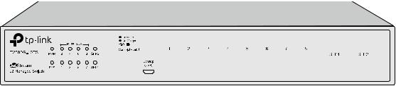
2.2.1 Front Panel
|
|
|
|
|
|
|
|
|
|
|
|
|
|
|
|
|
|
|
|
|
|
|
|
|
|
|
|
|
|
|
|
|
|
|
|
|
|
|
|
|
|
|
|
|
|
|
|
|
|
|
|
|
|
|
|
|
|
|
|
|
|
|
|
|
|
|
|
|
|
|
|
|
|
|
|
|
|
|
|
|
|
|
|
|
|
|
|
|
|
|
|
|
|
|
|
|
|
|
|
|
|
|
|
|
|
|
|
|
|
|
|
|
|
|
|
|
|
|
|
|
|
|
|
|
|
|
|
|
|
|
|
|
|
|
|
|
|
|
|
|
|
|
|
|
|
|
|
|
|
|
|
|
|
|
|
|
|
|
|
|
|
|
|
|
|
|
|
|
|
|
Figure 2-1 Front Panel |
||||||||||||||||||||||||||||||||||||||||||||
The following parts are located on the front panel of the switch: |
|||||||||||||||||||||||||||||||||||||||||||||||||||||
|
Name |
Status |
|
|
Indication |
||||||||||||||||||||||||||||||||||||||||||||||||
|
PWR |
On |
|
|
Power is on. |
||||||||||||||||||||||||||||||||||||||||||||||||
|
Flashing |
|
|
Power supply is abnormal. |
|||||||||||||||||||||||||||||||||||||||||||||||||
|
|
Off |
|
|
Power is off or power supply is abnormal. |
||||||||||||||||||||||||||||||||||||||||||||||||
|
SYS |
On |
|
|
The switch is working abnormally. |
||||||||||||||||||||||||||||||||||||||||||||||||
|
Flashing |
|
|
The switch is working normally. |
|||||||||||||||||||||||||||||||||||||||||||||||||
|
|
Off |
|
|
The switch is working abnormally. |
||||||||||||||||||||||||||||||||||||||||||||||||
|
|
|
|
Green |
|
|
A 1000Mbps device is connected to the |
||||||||||||||||||||||||||||||||||||||||||||||
|
|
On |
|
|
|
corresponding port, but no activity. |
|||||||||||||||||||||||||||||||||||||||||||||||
|
|
|
|
|
|
|
|
|
|
||||||||||||||||||||||||||||||||||||||||||||
|
10/100/1000M |
|
|
|
A 10/100Mbps device is connected to the |
||||||||||||||||||||||||||||||||||||||||||||||||
|
|
|
Yellow |
|
|
||||||||||||||||||||||||||||||||||||||||||||||||
|
|
|
|
|
corresponding port, but no activity. |
||||||||||||||||||||||||||||||||||||||||||||||||
|
|
Flashing |
|
|
Data is being transmitted or received. |
||||||||||||||||||||||||||||||||||||||||||||||||
|
|
Off |
|
|
Not linked. |
||||||||||||||||||||||||||||||||||||||||||||||||
|
|
|
|
|
|
|
|
|
7 |
|
|
|
|
|
|
|
|
|
|
|
|
|
|
|
|
|
|
|
|
|
|
|
|
|
|
|
|
|
|
|
|
|
|
|
|||||||||
Name |
Status |
Indication |
|
|
On |
A 1000Mbps device is connected to the |
|
SFP1, SFP2 |
corresponding port, but no activity. |
||
|
|||
Flashing |
Data is being transmitted or received. |
||
|
|||
|
Off |
Not linked. |
Console (RJ-45) Port: Designed to connect with the serial port of a computer or terminal for monitoring and configuring the switch.
Console (USB) Port: Designed to connect with the USB port of a computer for monitoring and configuring the switch. The switch has an RJ-45 console port and a micro-USB console port available. Console input is active on only one console port at a time. By default, the micro-USB connector takes precedence over the RJ-45 connector.
10/100/1000Mbps RJ45 Ports: Designed to connect to the device with a bandwidth of 10Mbps, 100Mbps or 1000Mbps. Each 10/100/1000Mbps RJ45 port has a corresponding 10/100/1000M LED.
SFP Ports: Designed to install the SFP module. T2500G-10TS features 2 individual SFP ports and supports 1000M SFP module connection only.
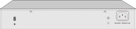
2.2.2 Rear Panel
The rear panel of T2500G-10TS features a power socket and a Grounding Terminal (marked with


 ).
).
Figure 2-2 Rear Panel
Kensington Security Slot: Secure the lock (not provided) into the security slot to prevent the device from being stolen.
Grounding Terminal: T2500G-10TS already comes with Lightning Protection Mechanism. You can also ground the switch through the PE (Protecting Earth) cable of AC cord or with Ground Cable. For detail information, please refer to Installation Guide.
AC Power Socket: Connect the female connector of the power cord here, and the male connector to the AC power outlet. Please make sure the voltage of the power supply meets the requirement of the input voltage (100-240V~ 50/60Hz 0.2A).
Return to CONTENTS
8
Chapter 3 Login to the Switch
3.1Login
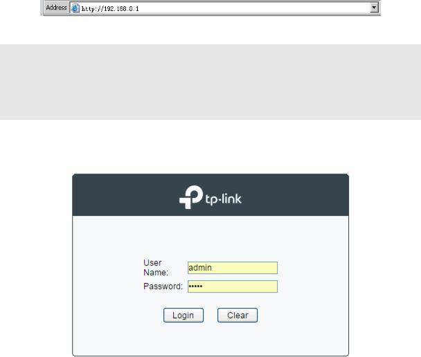
1.To access the configuration utility, open a web-browser and type in the default address http://192.168.0.1 in the address field of the browser, then press the Enter key.
Figure 3-1 Web-browser
 Tips:
Tips:
To log in to the switch, the IP address of your PC should be set in the same subnet addresses of the switch. The IP address is 192.168.0.x ("x" is any number from 2 to 254), Subnet Mask is 255.255.255.0.
2.After a moment, a login window will appear, as shown in Figure 3-2. Enter admin for the User Name and Password, both in lower case letters. Then click the Login button or press the
Enter key.
Figure 3-2 Login
3.2 Configuration
After a successful login, the main page will appear as Figure 3-3, and you can configure the function by clicking the setup menu on the left side of the screen.
9

Figure 3-3 Main Setup-Menu
 Note:
Note:
Clicking Apply can only make the new configurations effective before the switch is rebooted. If you want to keep the configurations effective even the switch is rebooted, please click Save Config. You are suggested to click Save Config before cutting off the power or rebooting the switch to avoid losing the new configurations.
Return to CONTENTS
10

Chapter 4 System
The System module is mainly for system configuration of the switch, including four submenus:
System Info, User Management, System Tools and Access Security.
4.1 System Info
The System Info, mainly for basic properties configuration, can be implemented on System Summary, Device Description, System Time, Daylight Saving Time, System IP and System IPv6 pages.
4.1.1 System Summary
On this page you can view the port connection status and the system information.
The port status diagram shows the working status of 8 10/100/1000Mbps RJ45 ports and 2 SFP ports of the switch. Ports 1-8 are 10/100/1000Mbps ports, and SFP1 and SFP2 are individual SFP ports.
Choose the menu System→System Info→System Summary to load the following page.
Figure 4-1 System Summary
Port Status
Indicates the 1000Mbps port is not connected to a device.
Indicates the 1000Mbps port is at the speed of 1000Mbps.
11
Indicates the 1000Mbps port is at the speed of 10Mbps or 100Mbps.
Indicates the SFP port is not connected to a device.
Indicates the SFP port is at the speed of 1000Mbps.
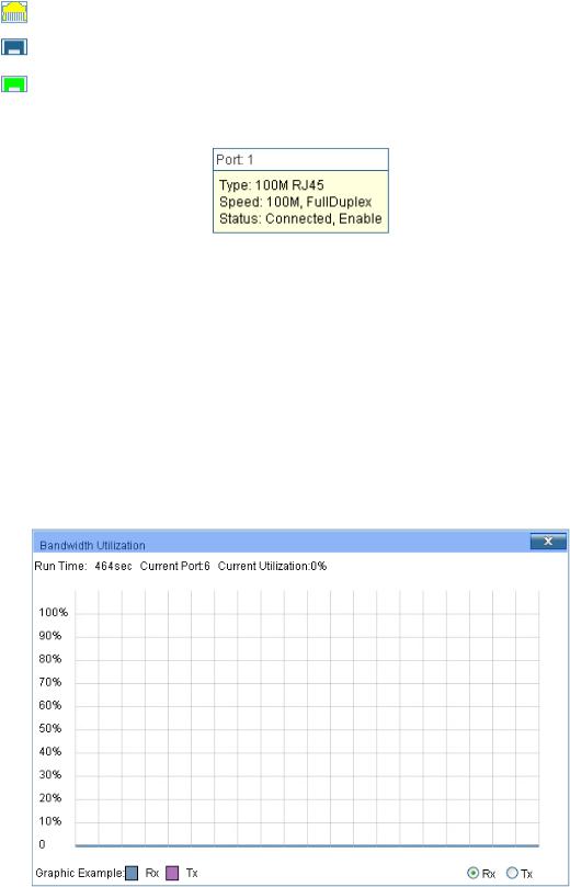
When the cursor moves on the port, the detailed information of the port will be displayed.
|
Figure 4-2 Port Information |
Port Info |
|
Port: |
Displays the port number of the switch. |
Type: |
Displays the type of the port. |
Rate: |
Displays the maximum transmission rate of the port. |
Status: |
Displays the connection status of the port. |
Click a port to display the bandwidth utilization on this port. The actual rate divided by theoretical maximum rate is the bandwidth utilization. Figure 4-3 displays the bandwidth utilization monitored every four seconds. Monitoring the bandwidth utilization on each port facilitates you to monitor the network traffic and analyze the network abnormities.
|
Figure 4-3 Bandwidth Utilization |
Bandwidth Utilization |
|
Rx: |
Select Rx to display the bandwidth utilization of receiving |
|
packets on this port. |
Tx: |
Select Tx to display the bandwidth utilization of sending packets |
|
on this port. |
|
12 |
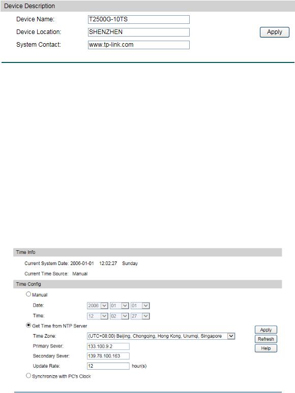
4.1.2 Device Description
On this page you can configure the description of the switch, including device name, device location and system contact.
Choose the menu System→System Info→Device Description to load the following page.
Figure 4-4 Device Description
The following entries are displayed on this screen:
Device Description
Device Name: Enter the name of the switch. Device Location: Enter the location of the switch. System Contact: Enter your contact information.
4.1.3 System Time
System Time is the time displayed while the switch is running. On this page you can configure the system time and the settings here will be used for other time-based functions like ACL.
You can manually set the system time, get UTC automatically if it has connected to an NTP server or synchronize with PC’s clock as the system time.
Choose the menu System→System Info→System Time to load the following page.
Figure 4-5 System Time
13

The following entries are displayed on this screen:
Time Info
Current System Date: Displays the current date and time of the switch. Current Time Source: Displays the current time source of the switch.
Time Config
Manual: |
When this option is selected, you can set the date and time |
|
manually. |
Get Time from NTP Server:
Synchronize with
PC’S Clock:
 Note:
Note:
When this option is selected, you can configure the time zone and the IP Address for the NTP Server. The switch will get UTC automatically if it has connected to an NTP Server.
Time Zone: Select your local time.
Primary/Secondary NTP Server: Enter the IP Address for the NTP Server.
Update Rate: Specify the rate fetching time from NTP server.
When this option is selected, the administrator PC’s clock is utilized.
1.The system time will be restored to the default when the switch is restarted and you need to reconfigure the system time of the switch.
2.When Get Time from NTP Server is selected and no time server is configured, the switch will get time from the time server of the Internet if it has connected to the Internet.
4.1.4 Daylight Saving Time
Here you can configure the Daylight Saving Time of the switch.
Choose the menu System→System Info→Daylight Saving Time to load the following page.
14

Figure 4-6 Daylight Saving Time
The following entries are displayed on this screen:
DST Config |
|
DST Status: |
Enable or Disable DST. |
Predefined Mode: |
Select a predefined DST configuration: |
|
USA: Second Sunday in March, 02:00 – First Sunday in |
|
November, 02:00. |
|
Australia: First Sunday in October, 02:00 – First Sunday in |
|
April, 03:00. |
|
Europe: Last Sunday in March, 01:00 – Last Sunday in |
|
October, 01:00. |
|
New Zealand: Last Sunday in September, 02:00 – First |
|
Sunday in April, 03:00. |
Recurring Mode: Specify the DST configuration in recurring mode. This configuration is recurring in use:
Offset: Specify the time adding in minutes when Daylight Saving Time comes.
Start/End Time: Select starting time and ending time of Daylight Saving Time.
Date Mode: Specify the DST configuration in Date mode. This configuration is one-off in use:
Offset: Specify the time adding in minutes when Daylight Saving Time comes.
Start/End Time: Select starting time and ending time of Daylight Saving Time.
15
 Note:
Note:
1.When the DST is disabled, the predefined mode, recurring mode and date mode cannot be configured.
2.When the DST is enabled, the default daylight saving time is of Europe in predefined mode.
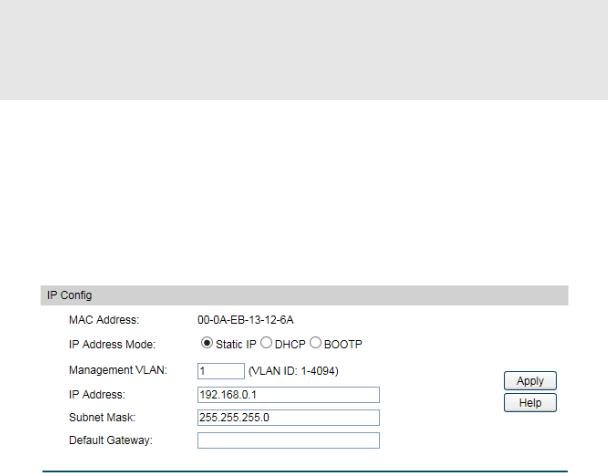
4.1.5 System IP
Each device in the network possesses a unique IP Address. You can log on to the Web management page to operate the switch using this IP Address. The switch supports three modes to obtain an IP address: Static IP, DHCP and BOOTP. The IP address obtained using a new mode will replace the original IP address. On this page you can configure the system IP of the switch.
Choose the menu System→System Info→System IP to load the following page.
Figure 4-7 System IP
The following entries are displayed on this screen:
IP Config
MAC Address: Displays MAC Address of the switch.
IP Address Mode: Select the mode to obtain IP Address for the switch.
Static IP: When this option is selected, you should enter IP Address, Subnet Mask and Default Gateway manually.
DHCP: When this option is selected, the switch will obtain network parameters from the DHCP Server.
BOOTP: When this option is selected, the switch will obtain network parameters from the BOOTP Server.
Management VLAN: Enter the ID of management VLAN, the only VLAN through which you can get access to the switch. By default VLAN1 owning all the ports is the Management VLAN and you can access the switch via any port on the switch. However, if another VLAN is created and set to be the Management VLAN, you may have to reconnect the management station to a port that is a member of the Management VLAN.
IP Address: Enter the system IP of the switch. The default system IP is 192.168.0.1 and you can change it appropriate to your needs.
16

Subnet Mask: Enter the subnet mask of the switch.
Default Gateway: Enter the default gateway of the switch.
 Note:
Note:
1.Changing the IP address to a different IP segment will interrupt the network communication, so please keep the new IP address in the same IP segment with the local network.
2.The switch only possesses an IP address. The IP address configured will replace the original IP address.
3.If the switch gets the IP address from DHCP server, you can see the configuration of the switch in the DHCP server; if DHCP option is selected but no DHCP server exists in the network, the switch will keep obtaining IP address from DHCP server until success.
4.If DHCP or BOOTP option is selected, the switch will get network parameters dynamically from the Internet, which means that its IP address, subnet mask and default gateway cannot be configured.
5.By default, the IP address is 192.168.0.1.
4.1.6 System IPv6
IPv6 (Internet Protocol version 6), also called IPng (IP next generation), was developed by the IETF (Internet Engineering Task Force) as the successor to IPv4 (Internet Protocol version 4). Compared with IPv4, IPv6 increases the IP address size from 32 bits to 128 bits; this solves the IPv4 address exhaustion problem.
IPv6 features
IPv6 has the following features:
1.Adequate address space: The source and destination IPv6 addresses are both 128 bits (16 bytes) long. IPv6 can provide 3.4 x 1038 addresses to completely meet the requirements of hierarchical address division as well as allocation of public and private addresses.
2.Header format simplification: IPv6 cuts down some IPv4 header fields or move them to IPv6 extension headers to reduce the load of basic IPv6 headers, thus making IPv6 packet handling simple and improving the forwarding efficiency. Although the IPv6 address size is four times that of IPv4 addresses, the size of basic IPv6 headers is 40 bytes and is only twice that of IPv4 headers (excluding the Options field).
3.Flexible extension headers: IPv6 cancels the Options field in IPv4 packets but introduces multiple extension headers. In this way, IPv6 enhances the flexibility greatly to provide scalability for IP while improving the handling efficiency. The Options field in IPv4 packets contains 40 bytes at most, while the size of IPv6 extension headers is restricted by that of IPv6 packets.
4.Built-in security: IPv6 uses IPSec as its standard extension header to provide end-to-end security. This feature provides a standard for network security solutions and improves the interoperability between different IPv6 applications.
17

5.Automatic address configuration: To simplify the host configuration, IPv6 supports stateful and stateless address configuration.
Stateful address configuration means that a host acquires an IPv6 address and related information from a server (for example, DHCP server).
Stateless address configuration means that a host automatically configures an IPv6 address and related information on basis of its own link-layer address and the prefix information advertised by a router.
In addition, a host can generate a link-local address on basis of its own link-layer address and the default prefix (FE80::/64) to communicate with other hosts on the link.
6.Enhanced neighbor discovery mechanism: The IPv6 neighbor discovery protocol is a group of Internet control message protocol version 6 (ICMPv6) messages that manages the information exchange between neighbor nodes on the same link. The group of ICMPv6 messages takes the place of Address Resolution Protocol (ARP) message, Internet Control Message Protocol version 4 (ICMPv4) router discovery message, and ICMPv4 redirection message to provide a series of other functions.
Introduction to IPv6 address
1.IPv6 address format
An IPv6 address is represented as a series of 16-bit hexadecimals, separated by colons (:). An IPv6 address is divided into eight groups, and the 16 bits of each group are represented by four hexadecimal numbers which are separated by colons, for example, 2001:0d02:0000:0000:0014: 0000:0000:0095. The hexadecimal letters in IPv6 addresses are not case-sensitive.
To simplify the representation of IPv6 addresses, zeros in IPv6 addresses can be handled as follows:
Leading zeros in each group can be removed. For example, the above-mentioned address can be represented in shorter format as 2001:d02:0:0:14:0:0:95.
Two colons (::) may be used to compress successive hexadecimal fields of zeros at the beginning, middle, or end of an IPv6 address. For example, the above-mentioned address can be represented in the shortest format as 2001:d02::14:0:0:95.
 Note:
Note:
Two colons (::) can be used only once in an IPv6 address to represent the longest successive hexadecimal fields of zeros. Otherwise, the device is unable to determine how many zeros double-colons represent when converting them to zeros to restore a 128-bit IPv6 address.
An IPv6 address consists of two parts: address prefix and interface ID. The address prefix and the interface ID are respectively equivalent to the network ID and the host ID in an IPv4 address.
18
An IPv6 address prefix is represented in "IPv6 address/prefix length" format, where "IPv6 address" is an IPv6 address in any of the above-mentioned formats and "prefix length" is a decimal number indicating how many leftmost bits from the preceding IPv6 address are used as the address prefix.
2.IPv6 address classification
IPv6 addresses fall into three types: unicast address, multicast address, and anycast address.
Unicast address: An identifier for a single interface, on a single node. A packet that is sent to a unicast address is delivered to the interface identified by that address.
Multicast address: An identifier for a set of interfaces (typically belonging to different nodes), similar to an IPv4 multicast address. A packet sent to a multicast address is delivered to all interfaces identified by that address. There are no broadcast addresses in IPv6. Their function is superseded by multicast addresses.
Anycast address: An identifier for a set of interfaces (typically belonging to different nodes). A packet sent to an anycast address is delivered to one of the interfaces identified by that address (the nearest one, according to the routing protocols’ measure of distance).
The type of an IPv6 address is designated by the first several bits called format prefix. The following table lists the mappings between address types and format prefixes.
|
Type |
Format Prefix (binary) |
|
IPv6 Prefix ID |
|
Unassigned address |
00…0 (128 bits) |
|
::/128 |
|
|
|
|
|
|
Loopback address |
00…1 (128 bits) |
|
::1/128 |
|
|
|
|
|
Unicast |
Link-local address |
1111111010 |
|
FE80::/10 |
|
|
|
|
|
|
|
|
|
|
address |
Site-local address |
1111111011 |
|
FEC0::/10 |
|
|
|
|
|
|
Global unicast address |
001 |
|
2xxx::/4 or 3xxx::/4 |
|
(currently assigned) |
|
||
|
|
|
|
|
|
Reserved type |
Other formats |
|
|
|
(to be assigned in future) |
|
|
|
|
|
|
|
|
Multicast address |
11111111 |
|
FF00::/8 |
|
|
|
|
|
|
|
|
Anycast addresses are taken from unicast |
||
Anycast address |
address space and |
are not syntactically |
||
|
|
distinguishable from unicast addresses. |
||
Table 4-1 Mappings between address types and format prefixes |
||||
|
|
19 |
|
|
IPv6 unicast address can be classified into several types, including global unicast address, link-local address, and site-local address. The two most common types are introduced below:
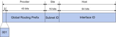
Global unicast address
A Global unicast address is an IPv6 unicast address that is globally unique and is routable on the global Internet.
Global unicast addresses are defined by a global routing prefix, a subnet ID, and an interface ID. Except for addresses that start with binary 000, all global unicast addresses have a 64-bit interface ID. The IPv6 global unicast address allocation uses the range of addresses that start with binary value 001 (2000::/3). The figure below shows the structure of a global unicast address.
Figure 4-8 Global Unicast Address Format
An interface ID is used to identify interfaces on a link. The interface ID must be unique to the link. It may also be unique over a broader scope. In many cases, an interface ID will be the same as or based on the link-layer address of an interface. Interface IDs used in global unicast and other IPv6 address types must be 64 bits long and constructed in the modified extended universal identifier (EUI)-64 format.
For all IEEE 802 interface types (for example, Ethernet and FDDI interfaces), Interface IDs in the modified EUI-64 format are constructed in the following way:
the first three octets (24 bits) are taken from the Organizationally Unique Identifier (OUI) of the 48-bit link-layer address (the media access control, or MAC, address) of the interface, the fourth and fifth octets (16 bits) are a fixed hexadecimal value of FFFE, and the last three octets (24 bits) are taken from the last three octets of the MAC address. The construction of the interface ID is completed by setting the universal/local (U/L) bit--the seventh bit of the first octet--to a value of 0 or 1. A value of 0 indicates a locally administered identifier; a value of 1 indicates a globally unique IPv6 interface identifier.
Take MAC address 0012:0B0A:2D51 as an example. Insert FFFE to the middle of the address to get 0012:0BFF:FE0A:2D51. Then set the U/L bit to 1 to obtain an interface ID in EUI-64 format as 0212:0BFF:FE0A:2D51.
Link-local address
A link-local address is an IPv6 unicast address that can be automatically configured on any interface using the link-local prefix FE80::/10 (1111 1110 10) and the interface identifier in the modified EUI-64 format. Link-local addresses are used in the neighbor discovery protocol and the stateless autoconfiguration process. Nodes on a local link
20
Loading...