


 Loading...
TL-SC3000
3GPP Surveillance Camera
Rev:1.0.0
1910010104
COPYRIGHT & TRADEMARKS
Specifications are subject to change without notice.  is a registered trademark of TP-LINK TECHNOLOGIES CO., LTD. Other brands and product names are trademarks or registered trademarks of their respective holders.
No part of the specifications may be reproduced in any form or by any means or used to make any derivative such as translation, transformation, or adaptation without permission from TP-LINK TECHNOLOGIES CO., LTD. Copyright © 2008 TP-LINK TECHNOLOGIES CO., LTD. All rights reserved.
http://www.tp-link.com

FCC STATEMENT
This equipment has been tested and found to comply with the limits for a Class B digital device, pursuant to part 15 of the FCC Rules. These limits are designed to pro-vide reasonable protection against harmful interference in a residential installation. This equipment generates, uses and can radiate radio frequency energy and, if not in-stalled and used in accordance with the instructions, may cause harmful interference to radio communications. However, there is no guarantee that interference will not occur in a particular installation. If this equipment does cause harmful interference to radio or television reception, which can be determined by turning the equipment off and on, the user is encouraged to try to correct the interference by one or more of the following measures:
¾Reorient or relocate the receiving antenna.
¾Increase the separation between the equipment and receiver.
¾Connect the equipment into an outlet on a circuit different from that to which the receiver is connected.
¾Consult the dealer or an experienced radio/ TV technician for help.
This device complies with part 15 of the FCC Rules. Operation is subject to the following two conditions:
1)This device may not cause harmful interference.
2)This device must accept any interference received, including interference that may cause undesired operation.
Any changes or modifications not expressly approved by the party responsible for compliance could void the user’s authority to operate the equipment.
CE Mark Warning
This is a class B product. In a domestic environment, this product may cause radio interference, in which case the user may be required to take adequate measures.
|
CONTENTS |
|
Package Contents .................................................................................................................................. |
1 |
|
Chapter 1. |
Product Overview .......................................................................................................... |
2 |
1.1 |
Description....................................................................................................................... |
2 |
1.2 |
Features........................................................................................................................... |
2 |
1.3 |
Specifications ................................................................................................................. |
3 |
Chapter 2. |
Hardware Overview........................................................................................................ |
4 |
2.1 |
Rear Panel....................................................................................................................... |
4 |
2.2 |
Upper Side & Underside .................................................................................................. |
5 |
Chapter 3. |
Installation ...................................................................................................................... |
5 |
3.1 |
Install the Hardware ......................................................................................................... |
5 |
3.2 |
Assign an IP address and Access the Camera ................................................................ |
9 |
Chapter 4. |
Video Viewer Basic Operation .................................................................................... |
11 |
4.1 |
The Live View Page ....................................................................................................... |
11 |
4.2 |
Address Book................................................................................................................. |
12 |
4.3 |
Manual Record............................................................................................................... |
13 |
4.4 |
Playback ........................................................................................................................ |
15 |
4.5 |
Snapshot........................................................................................................................ |
16 |
4.6 |
Information..................................................................................................................... |
17 |
Chapter 5. |
Video Viewer Miscellaneous Control Panel ............................................................... |
18 |
5.1 |
Color Setting .................................................................................................................. |
19 |
5.2 |
Backup (For DVR only) .................................................................................................. |
20 |
5.3 |
Record Setting ............................................................................................................... |
21 |
5.4 |
Server Setting ................................................................................................................ |
24 |
5.4.1 |
General.................................................................................................................. |
24 |
5.4.2 |
Network ................................................................................................................. |
29 |
5.4.3 |
Video...................................................................................................................... |
35 |
5.5 |
Tools .............................................................................................................................. |
36 |
5.5.1 |
Firmware Upgrade................................................................................................. |
36 |
5.5.2 |
Language Selection............................................................................................... |
37 |
5.6 |
Status List ...................................................................................................................... |
38 |
5.6.1 |
Record ................................................................................................................... |
38 |
5.6.2 |
Event ..................................................................................................................... |
40 |
5.6.3 |
Backup (For DVR only).......................................................................................... |
40 |
5.6.4 |
Playback Screen.................................................................................................... |
41 |
Chapter 6. |
IE Web Browser............................................................................................................ |
42 |
6.1 |
Access the Camera from an IE Web Browser................................................................ |
42 |
6.2 |
Toolbar Display on the IE Web Browser......................................................................... |
43 |
Chapter 7. |
QuickTime Player......................................................................................................... |
45 |
Chapter 8. |
Monitoring via Mobile Device...................................................................................... |
47 |
8.1 |
Checklist before using.................................................................................................... |
47 |
8.2 |
Installation and Setup .................................................................................................... |
47 |
8.2.1 |
Software download ................................................................................................ |
47 |
8.2.2 |
GPRS / 3G Mobile Phone...................................................................................... |
48 |
8.2.3 |
PDA ....................................................................................................................... |
49 |
8.3 |
Available Functions........................................................................................................ |
51 |
8.3.1 |
GPRS / 3G Mobile Phone...................................................................................... |
51 |
8.3.2 |
PDA ....................................................................................................................... |
51 |
Appendix 1 Recording Time Table.................................................................................................. |
53 |
|
Appendix 2 User Level For Remote Operation .............................................................................. |
55 |
|
Appendix 3 |
Default Value ................................................................................................................ |
55 |

TL-SC3000 3GPP Surveillance Camera
Package Contents
The following items should be found in your package:
¾One TL-SC3000 3GPP Surveillance Camera
¾One Adapter and power cord
¾One Bracket
¾One RJ45 network cable
¾Quick Installation Guide
¾One Resource CD , including: z This User Guide
z Video Viewer AP Software
)Note:
Make sure that the package contains the above items. If any of the listed items are damaged or missing, please contact with your distributor.
1

TL-SC3000 3GPP Surveillance Camera
Chapter 1. Product Overview
1.1 Description
This camera series is a network-based digital surveillance device with a built-in web server for the purpose of remote monitoring and recording. It supports TCP/IP networking for live video transmission in the format of H.264, MPEG4 or MJPEG, and you can easily operate the camera via the web browser or the supplied video viewer AP software. Video surveillance over IP network infrastructure is available and easy from anywhere, at anytime.
1.2 Features
¾Low-latency video streaming for sharp and clear images
¾Hybrid digital / analog video output
¾Multi-area, multi-level sensitivity motion detection
¾3GPP Support
¾High quality 1/3.6’’ Panasonic MOS Sensor
2
|
|
|
|
TL-SC3000 |
|
3GPP Surveillance Camera |
|
|
|
|
|
|
|
|
|
|
|
|
|
1.3 Specifications* |
|
|
|
|
|
|
|
||
|
|
|
|
|
|
|
|||
|
|
|
|
|
|
|
|||
|
|
SPECIFICATIONS |
|
TL-SC3000 |
|
||||
|
|
Network |
|
|
|
|
|
|
|
|
|
LAN Port |
|
YES |
|
||||
|
|
LAN Speed |
|
10/100 Based-T Ethernet |
|
||||
|
|
Supported Protocols |
DDNS, PPPoE, DHCP, NTP, SNTP, TCP/IP, |
|
|||||
|
|
ICMP, SMTP, FTP, HTTP, RTP, RTSP |
|
||||||
|
|
|
|
||||||
|
|
Frame Rate |
|
NTSC:30fps, PAL:25fps |
|
||||
|
|
Number of Online Users |
|
10 |
|
|
|
||
|
|
Security |
Multiple user access levels with password |
|
|||||
|
|
Web management software |
YES (Control up to 16 network cameras simultaneously) |
|
|||||
|
|
Video / Audio |
|
|
|
|
|
|
|
|
|
Video Compression |
|
MPEG4 / MJPEG |
|
||||
|
|
Video Remote Control |
|
YES |
|
||||
|
|
Video Adjustment |
Brightness, Contrast, Saturation and Hue |
|
|||||
|
|
Camera |
|
|
|
|
|
|
|
|
|
Image Sensor |
|
1/3.6" image sensor |
|
||||
|
|
Pixels |
|
640(H) x 480(V) |
|
||||
|
|
Lens |
|
f3.6mm |
|
||||
|
|
F-number |
|
F2.0 |
|
||||
|
|
Viewing Angle |
80° |
|
55.6° |
|
|
||
|
|
Shutter Speed |
|
1 / 60 (1/50) to 1 / 100,000 sec. |
|
||||
|
|
Min Illumination |
|
1 Lux / F2.0 |
|
||||
|
|
Video Output |
|
1.0 Vp-p. 75Ω |
|
||||
|
|
BLC |
|
AUTO |
|
||||
|
|
White Balance |
|
ATW |
|
||||
|
|
Others |
|
|
|
|
|
|
|
|
|
Remote Control |
|
YES |
|
||||
|
|
Motion Detection |
|
YES |
|
||||
|
|
Power |
|
DC12V, 1A |
|
||||
|
|
Operating Temperature |
|
0~40 |
|
||||
|
|
Humidity |
|
85% |
|
|
|||
|
|
|
·Pentium 4 CPU 1.3 GHz or higher, or equivalent AMD |
|
|||||
|
|
Minimum Web |
·256 MB RAM |
|
|
|
|
|
|
|
|
·AGP graphics card, Direct Draw, 32MB RAM |
|
||||||
|
|
Browsing Requirements |
|
||||||
|
|
·Windows XP, Windows 2000 Server, ME, 98, DirectX 9.0 or later |
|
||||||
|
|
|
|
||||||
|
|
|
·Internet Explorer 6.x or later |
|
|||||
|
|
Dimensions (L x W x H)** |
152.5 x 115.2 x 40.2 mm (6.00” x 4.54” x 1.58”) |
|
|||||
|
|
Shipping Weight |
812g (1.79 lbs) including mounting bracket and power supply |
|
|||||
|
|
Indoor / Outdoor Application |
|
Indoor |
|
||||
|
|
|
|
|
|
|
|
|
|
* The specifications are subject to change without notice. ** Dimensional tolerance: ± 5mm
3

TL-SC3000 3GPP Surveillance Camera
Dimensions: 152.5 (L) x 115.2 (W) x 40.2 (H) mm
Chapter 2. Hardware Overview
2.1 Rear Panel
CONNECTOR / BUTTON |
DESCRIPTION |
|
|
Reset Default |
This button is hidden in the pinhole. Press and hold the reset |
|
button until the network camera reboots. This will reset all |
|
parameters, including the IP address to factory default settings. |
Power Indicator |
When the camera is power-supplied, this indicator will be on as |
|
red. |
Video Output |
Connect to the video input connector of your monitor with a video |
|
cable (i.e. a RCA line with the BNC connector, or a coaxial line) for |
|
video output. |
|
* The video cable is optional. |
LAN |
Connect the camera to the network with the supplied RJ45 cable. |
Power Connector |
Connect the DC 12V adapter for power supply. |
4
TL-SC3000 3GPP Surveillance Camera
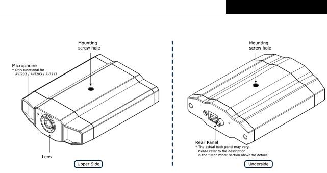
2.2 Upper Side & Underside
Chapter 3. Installation
3.1 Install the Hardware
This camera can be installed in two ways: ceiling-mounted and desktop. During the installation, please make sure the upper side of the camera is always facing up, as shown in Figure 1 below, regardless of which installation way you’re using. This is to ensure the video output won’t be up side down.
)Note:
¾The illustrations below are based on the ceiling-mounted installation.
¾For the detailed cable connection, please refer to the section “Rear Panel” on Page 4. Tool needed: Power drill x 1 (not supplied within the sales package)
1.Prepare all the parts needed for camera installation.
Find the network camera, bracket package, a bag of screws & wall plugs, and a cap supplied with the sales package, as shown in Figure 3-1.
Unpack the bracket package to find the bracket disassembled into three parts: the base, stem and joint lock.
5
TL-SC3000 3GPP Surveillance Camera
Figure 3-1 Parts needed for camera installation
2.Fix the base of the bracket.
Fix the base of the bracket with the supplied 3 screws to the place you want to install by using a power drill.
Figure 3-2 Screw the base to the ceiling
3.Assemble the bracket:
a)Align the stem with the central hole of the base, and rotate it to secure, as shown in Figure 3-3.
b)Align the joint lock with the stem, and rotate it to secure, as shown in Figure 3-4.
6

TL-SC3000 3GPP Surveillance Camera
Figure 3-3 Connect the stem to the base
Figure 3-4 Connect the joint lock to the stem
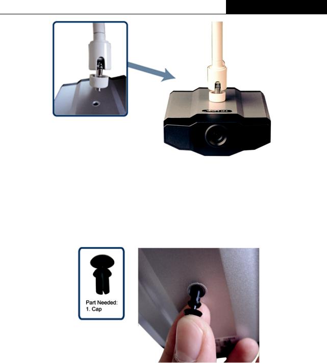
4.Connect the camera to the bracket.
Ceiling-mounted:
With the upper side of the camera facing up, align the mounting screw hole on the upper side with the screw thread of the joint lock, and rotate the camera to secure, as shown in Figure 3-5.
Desktop:
With the upper side of the camera facing up, align the mounting screw hole on the underside with the screw thread of the joint lock, and rotate the camera to secure.
7
TL-SC3000 3GPP Surveillance Camera
Figure 3-5 Connect the camera to the bracket
5.Insert the cap to the other mounting screw hole of the camera.
Ceiling-mounted:
Insert the cap to the mounting screw hole on the underside of the camera, as shown in Figure 3-6.
Desktop:
Insert the cap to the mounting screw hole on the upper side of the camera.
Figure 3-6 Insert the cap to the camera
6.Adjust the viewing angle of the camera, and fasten the joint lock to fix the angle. The installation is completed, as shown in Figure 3-7.
8
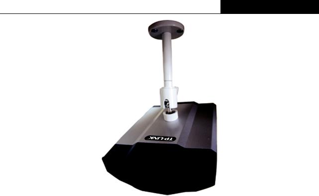
TL-SC3000 3GPP Surveillance Camera
Figure 3-7 Finish the installation
3.2 Assign an IP address and Access the Camera
Step 1. Install the Software
Place the supplied Video Viewer AP software CD into your DVD- / CD-ROM drive. The installation process will automatically start. Follow the on-screen instructions to install the application programs. After installation, a “Video Viewer” shortcut icon will be shown on your PC desktop.
Step 2. Connect the network camera to the Internet access via a RJ-45 network cable.
Step 3. Search the available IP address to login
Double-click “ ” icon on your PC desktop to enter the Video Viewer control panel. By defaults, the “Address Book” (
 ) panel will be displayed on the right side of the Video Viewer control panel.
Click ” ” (Search) Æ ”
 ” (Refresh) to search the available IP address(es). The found address(es) will be listed, and can be added into the address book by clicking ”
 ” (Add into address book).
For details, please see “ ” (Search) in the user manual.
Select the IP address you just added into the address book, and click “ ” (Edit) to edit the settings.
Double-click the IP address in the address book to login.
)Note:
For detailed network settings under different network types (Static IP / PPPOE / DHCP), please refer to “Network” and “DDNS” in the user manual.
If you cannot search any available IP address, please follow the instructions below. Step 4. Add the IP address and other network settings to login
a) Double-click “ ” icon on your PC desktop to enter the Video Viewer control panel. By defaults,
9

TL-SC3000 3GPP Surveillance Camera
the “Address Book” panel will be displayed on the right side of the Video Viewer control panel.
b) The default network camera settings are as follows:
Item |
Default Setting |
|
|
IP Address |
192.168.1.10 |
|
|
User Name |
admin |
|
|
Password |
admin |
|
|
Port Number |
80 |
|
|
c)Click ” ” (Address Book) Æ ”
 ” (Add) button to key in the IP address, user name, password, and port number of the network camera you intend to connect.
Item |
Default Setting |
IP Address |
192.168.1.10 |
|
|
User Name |
admin |
|
|
Password |
admin |
|
|
Port Number |
80 |
|
|
d) Double-click the IP address you just added into the address book to login.
10

TL-SC3000 3GPP Surveillance Camera
Chapter 4. Video Viewer Basic Operation
4.1 The Live View Page
After setting up the network information, login user name and password, double-click “ ” on the PC desktop to open and log into the Video Viewer control panel. You will see a screen similar to the following with 6 major sections:
Connect to only one network camera |
Connect to multiple network cameras (e.g. 4 |
|
cameras) |
||
|
||
1-cut display |
4-cut display |
|
|
|
|
NO. |
Button |
|
Function |
|
Description |
|
|
|
|
|
|
To switch to another camera view if two or more |
|
|
|
|
|
|
network cameras are connected, click the |
|
|
|
|
|
|
corresponding blue tab. The camera title shown in the |
|
|
|
|
Image Display |
|
blue tab can be customized (For example, “01”, “02”, |
|
|
|
|
|
|
“03” and “04”). The default camera title is “Camera1”. |
|
|
|
|
|
|
For detailed camera title setting, please refer to |
|
|
|
|
|
|
“General” on Page 24. The software can control up to |
|
|
|
|
|
16 network cameras simultaneously. |
|
|
|
|
|
|
|
|
|
|
|
|
Scale |
|
Click to view the images in the 1-cut, 4-cut, 9-cut and |
|
|
|
|
|
16-cut mode. |
|
|
|
|
|
|
||
|
|
|
|
|
|
|
|
|
|
|
|
|
Click to view the images in the full screen mode. To exit |
|
|
|
|
Full Screen |
|
the full screen mode, press “Esc” key on the keyboard |
|
|
|
|
|
|
of the PC. |
|
|
|
|
|
|
|
|
|
|
|
|
|
Click to close the current image display view. |
|
|
|
|
Close |
|
If the image display view is closed, you will be logged |
|
|
|
|
|
|
out automatically. |
|
|
|
|
|
|
|
|
|
|
|
Close All |
|
Click to close all the current image display view. |
|
|
|
|
|
If the image display view is closed, you will be logged |
|
|
|
|
|
|
|
out automatically. |
|
|
|
|
|
|
|
11
|
|
|
|
TL-SC3000 |
3GPP Surveillance Camera |
|
|
|
|
|
|
|
|
|
|
|
|
|
|
|
|||
|
|
|
|
Click to show the predefined IP address(es). You can |
|||
|
|
Address Book |
add, remove or search the IP address to log in the |
||||
|
|
|
|
network camera remotely. |
|||
|
|
|
|
|
|||
|
|
Miscellaneous |
Click to show the main operation functions: audio |
||||
|
Control |
volume control, color setting, backup, record setting, |
|||||
|
|
|
server setting, upgrade, and find status log list. |
||||
|
|
|
|
||||
|
|
|
|
|
|
|
|
|
/ |
Record / |
Click to start / stop the manual recording. |
||||
Stop Record |
|||||||
|
|
|
|
|
|
||
|
|
|
|
|
|||
|
|
|
Snapshot |
Click to take a snapshot of the current view. The |
|||
|
|
snapshot will be saved in the path you specified in |
|||||
|
|
|
|
“Record Setting” on Page 21. |
|||
|
|
|
|
||||
|
|
Information |
Click to show the current network connection details. |
||||
|
|
|
|
|
|
||
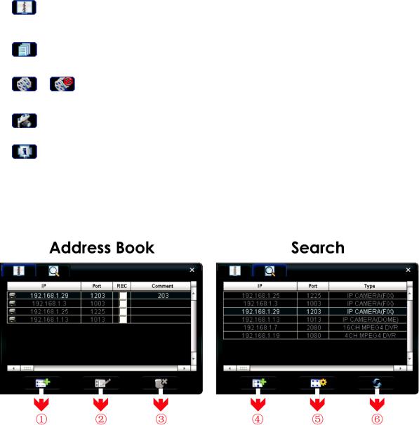
4.2 |
Address Book |
|
|
|
|
||
This view is displayed when the Video Viewer is activated for you to log in / out the network camera from the current address list, or search the available IP address as follows:
¾ (Address Book)
Click to view the pre-defined network camera access details.
To log in, choose one IP address from the address list, and click the address twice; to log out, click the connected IP address twice.
You can also create new IP address information, or modify or remove the current IP address information.
12

TL-SC3000 3GPP Surveillance Camera
NO. |
|
Button |
|
Function |
|
Description |
|
|
|
|
|
|
|
|
|
|
|
|
|
Click to directly add one IP address for login. Key in all the network |
|
|
|
|
|
|
camera access information needed, and click “Apply” and “Close” |
|
|
|
|
|
|
to add the selected address to the address book. |
1 |
|
|
|
Add |
|
|
|
|
|
|
|
|
|
2 |
|
|
|
Edit |
|
Select one current IP address from the address list, and click this |
|
|
|
|
button to edit the settings. |
||
|
|
|
|
|
|
|
3 |
|
|
|
Remove |
|
Select one IP address from the address list, and click this button to |
|
|
|
|
delete it. |
||
|
|
|
|
|
|
|
|
|
|
|
|
|
Check this checkbox to enable the record settings. For details, |
|
|
|
|
Record |
|
please refer to the “Record Setting” on Page 21. The default |
|
|
|
|
|
|
setting is unchecked. |
¾ (Search)
Click to search and view the available IP address(es) for the network camera connection. You can choose one address to add into the address book, edit the details, or update the address list.
NO. |
Button |
Function |
Add into 4  address
book
5 |
Setting |
|
|
6 |
Refresh |
Description
Select from the available IP address list, and click this button. Key in the network camera access information needed, and click “Apply” and “Close” to add the selected address to the address book.
Select from the available IP address list, and click this button to edit the setting.
Click to update the available IP address list.
4.3 Manual Record
1)Choose the record type and assign the record location
Click “ ” (Miscellaneous Control) → “
 ” (Record Setting) to go to the “Record Setting”
13
Loading...