


 Loading...
User Guide
Gigabit Easy Smart Switch
TL-SG1016DE/TL-SG1024DE/TL-SG1016PE TL-SG105E/TL-SG108E/TL-SG108PE
1910012338 REV3.1.1
December 2017
|
|
|
CONTENTS |
Package Contents ........................................................................................................................... |
1 |
||
Chapter 1 About this Guide............................................................................................................ |
2 |
||
1.1 |
Intended Readers .......................................................................................................... |
2 |
|
1.2 |
Conventions .................................................................................................................. |
2 |
|
1.3 |
Overview of This Guide.................................................................................................. |
3 |
|
Chapter 2 |
Introduction................................................................................................................... |
5 |
|
2.1 |
Overview of the Switch.................................................................................................. |
5 |
|
2.2 |
Appearance Description ............................................................................................... |
5 |
|
2.2.1 |
Front Panel .......................................................................................................... |
5 |
|
2.2.2 |
Rear Panel ........................................................................................................... |
9 |
|
Chapter 3 Log In to the Switch ..................................................................................................... |
11 |
||
3.1 |
Login |
............................................................................................................................. |
11 |
3.2 |
Configuration............................................................................................................... |
12 |
|
Chapter 4 |
System ........................................................................................................................ |
13 |
|
4.1 |
System ..................................................................................................................Info |
13 |
|
4.2 |
IP Setting...................................................................................................................... |
13 |
|
4.3 |
User Account............................................................................................................... |
14 |
|
4.4 |
System ...............................................................................................................Tools |
15 |
|
4.4.1 ......................................................................................... |
Backup and Restore |
15 |
|
4.4.2 ................................................................................................. |
System Reboot |
17 |
|
4.4.3 .................................................................................................... |
System Reset |
17 |
|
4.4.4 ............................................................................................ |
Firmware Upgrade |
18 |
|
Chapter 5 |
Switching..................................................................................................................... |
20 |
|
5.1 |
Port Setting.................................................................................................................. |
20 |
|
5.2 |
IGMP Snooping............................................................................................................ |
21 |
|
5.3 |
LAG............................................................................................................................... |
|
22 |
Chapter 6 |
Monitoring ................................................................................................................... |
24 |
|
6.1 |
Port Statistics .............................................................................................................. |
24 |
|
6.2 |
Port Mirror.................................................................................................................... |
25 |
|
6.3 |
Cable ....................................................................................................................Test |
26 |
|
6.4 |
Loop Prevention .......................................................................................................... |
27 |
|
Chapter 7 VLAN............................................................................................................................ |
|
28 |
|
7.1 |
MTU VLAN.................................................................................................................... |
29 |
|
7.2 |
Port Based .........................................................................................................VLAN |
30 |
|
7.3 |
802.1Q VLAN ............................................................................................................... |
31 |
7.4 |
802.1Q PVID Setting.................................................................................................... |
32 |
Chapter 8 QoS.............................................................................................................................. |
34 |
|
8.1 |
QoS Basic .................................................................................................................... |
36 |
8.2 |
Bandwidth Control....................................................................................................... |
38 |
8.3 |
Storm Control .............................................................................................................. |
38 |
Chapter 9 |
PoE .............................................................................................................................. |
40 |
9.1 |
PoE Config ................................................................................................................... |
41 |
Appendix A: Specifications ........................................................................................................... |
43 |
|

Package Contents
The following items should be found in your box:
One Gigabit Easy Smart Switch
One power cord
Two mounting brackets and other fittings (for TL-SG1016DE/TL-SG1024DE/ TL-SG1016PE only)
Installation Guide
Resource CD for TL-SG105E/TL-SG108E/TL-SG108PE/TL-SG1016DE/TL-SG1024DE/ TL-SG1016PE switch, including:
•This User Guide
•Easy Smart Configuration Utility.exe
•Easy Smart Configuration Utility User Guide
•Other Helpful Information
 Note: Make sure that the package contains the above items. If any of the listed items are damaged or missing, please contact your distributor.
1

Chapter 1 About this Guide
This User Guide contains information for setup and management of TL-SG105E/TL-SG108E/ TL-SG108PE/TL-SG1016DE/TL-SG1024DE/TL-SG1016PE Gigabit Easy Smart Switch. Please read this guide carefully before operation.
1.1 Intended Readers
This Guide is intended for network managers familiar with IT concepts and network terminologies.
1.2 Conventions
When using this guide, please notice that features of the switch may vary slightly depending on the model and software version you have, and on your location, language, and Internet service provider. All screenshots, images, parameters and descriptions documented in this guide are used for demonstration only.
The information in this document is subject to change without notice. Every effort has been made in the preparation of this document to ensure accuracy of the contents, but all statements, information, and recommendations in this document do not constitute the warranty of any kind, express or implied. Users must take full responsibility for their application of any products.
In this Guide the following conventions are used:
The switch or TL-SG105E/TL-SG108E/TL-SG108PE/TL-SG1016DE/TL-SG1024DE/ TL-SG1016PE mentioned in this Guide stands for TL-SG105E/TL-SG108E/TL-SG108PE/ TL-SG1016DE/TL-SG1024DE/TL-SG1016PE Gigabit Easy Smart Switch without any explanation.
Menu Name→Submenu Name→Tab page indicates the menu structure. System→System Info→System Summary means the System Summary page under the System Info menu option that is located under the System menu.
Bold font indicates a button, a toolbar icon, menu or menu item.
Symbols in this Guide
Symbol |
Description |
|
Note: |
Ignoring this type of note might result in a malfunction or damage to the device. |
|
Tips: |
This format indicates important information that helps you make better use of |
|
your device. |
||
|
2 |
More Info:
The latest software, management app and utility can be found at Download Center at http://www.tp-link.com/support.
The Installation Guide (IG) can be found where you find this guide or inside the package of the switch.
Specifications can be found on the product page at http://www.tp-link.com.
A Technical Support Forum is provided for you to discuss our products at http://forum.tp-link.com.
Our Technical Support contact information can be found at the Contact Technical Support page at http://www.tp-link.com/support.
1.3 Overview of This Guide
Chapter |
Introduction |
||
Chapter 1 About This |
Introduces the guide structure and conventions. |
||
Guide |
|
|
|
Chapter 2 Introduction |
Introduces the features, application and appearance of |
||
|
TL-SG105E/TL-SG108E/TL-SG108PE/TL-SG1016DE/ |
||
|
TL-SG1024DE/TL-SG1016PE switch. |
||
Chapter 3 Login to the |
Introduces how to log on to the Web management page. |
||
Switch |
|
|
|
Chapter 4 System |
This module is used to configure system properties of the |
||
|
switch. Here mainly introduces: |
||
|
|
System Info: View device information and define the device |
|
|
|
description. |
|
|
|
IP Setting: Get and modify the network parameters of the |
|
|
|
switch. |
|
|
User Account: Modify the username and password for users |
||
|
|
to log on to the Web management page. |
|
|
System Tools: Manage the configuration file of the switch. |
||
Chapter 5 Switching |
Configure the basic functions of the switch. |
||
Chapter 6 Monitoring |
Monitor the traffic information of the switch, and provide the |
||
|
convenient method to locate and solve the network problem. |
||
Chapter 7 VLAN |
This module is used to configure VLANs to control broadcast in |
||
|
LANs. Here mainly introduces: |
||
|
MTU VLAN: Set the MTU VLAN mode. |
||
|
Port Based VLAN: Set the Port-Based VLAN mode |
||
|
802.1Q VLAN: Set the 802.1Q Tag VLAN mode. |
||
|
802.1Q PVID Setting: Configure 802.1Q PVID value. |
||
|
|
3 |
|
Chapter |
Introduction |
|
Chapter 8 QoS |
This module is used to configure QoS function to provide |
|
|
different quality of service for various network applications and |
|
|
requirements. Here mainly introduces: |
|
|
QoS Basic: Configure and view the basic parameters of QoS. |
|
|
Bandwidth Control: Configure and view the bandwidth |
|
|
control function information. |
|
|
Storm Control: Configure and view the storm control function |
|
|
information. |
|
Chapter 9 PoE |
This module is used to configure the PoE function for the switch to |
|
|
supply power for PD devices. |
|
Appendix A Specifications |
Lists the hardware specifications of the switch. |
Return to CONTENTS
4
Chapter 2 Introduction
Thanks for choosing the TL-SG105E/TL-SG108E/TL-SG108PE/TL-SG1016DE/TL-SG1024DE/ TL-SG1016PE Gigabit Easy Smart Switch!
2.1 Overview of the Switch
The TL-SG105E/TL-SG108E/TL-SG108PE/TL-SG1016DE/TL-SG1024DE/TL-SG1016PE Gigabit Easy Smart Switch is an ideal upgrade from an unmanaged switch, designed for Small and Medium Business networks that require simple network management. Network administrators can effectively monitor traffic via Port Mirroring, Loop Prevention and Cable Test features. To optimize traffic on your business network, they offer port-based, tag-based, DSCP-based QoS to keep latency-sensitive traffic moving smoothly and jitter-free. Additionally, port-based, tag-based and MTU VLAN can improve security and meet more network segmentation requirements. Moreover, with the innovative energy-efficient technology, they are eco-friendly solution for your business network.
 Note: For details about Easy Smart Configuration Utility, please refer to the User Guide of the Easy Smart Configuration Utility in the Resource CD.
2.2 Appearance Description
2.2.1 Front Panel
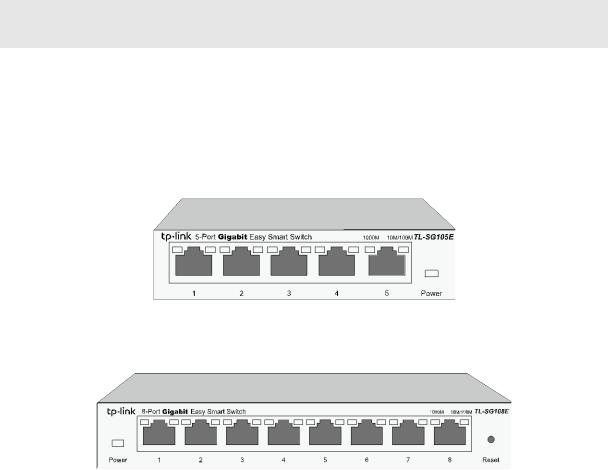
TL-SG105E/TL-SG108E
The front panel of TL-SG105E is shown as Figure 2-1.
Figure 2-1 Front Panel of TL-SG105E
The front panel of TL-SG108E is shown as Figure 2-2.
Figure 2-2 Front Panel of TL-SG108E
The following parts are located on the front panel of the switch:
Reset: With the switch powered on, press this button for five seconds or above to reset the software setting back to factory default setting. (For TL-SG108E only)
5
1000Mbps Ports: Designed to connect to the device with a bandwidth of 10Mbps, 100Mbps or 1000Mbps. Each has a corresponding 1000Mbps LED and 10/100Mbps LED.
LEDs
|
Name |
|
|
Status |
|
|
Indication |
|
Power |
|
|
On |
|
|
Power is on. |
|
|
|
Flashing |
|
|
Power supply is abnormal. |
|
|
|
|
|
Off |
|
|
Power is off or power supply is abnormal. |
|
|
|
|
On |
|
|
A 1000Mbps device is connected to the corresponding port. |
|
1000Mbps |
|
|
Flashing |
|
|
Data is being transmitted or received. |
|
|
|
Off |
|
|
A 10/100Mbps device or no device is connected to the |
|
|
|
|
|
|
|
||
|
|
|
|
|
|
corresponding port. |
|
|
|
|
|
|
|
|
|
|
|
|
|
On |
|
|
A 10/100Mbps device is connected to the corresponding port. |
|
10/100Mbps |
|
|
Flashing |
|
|
Data is being transmitted or received. |
|
|
|
|
Off |
|
|
No device is connected to the corresponding port. |
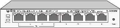
TL-SG108PE
The front panel of TL-SG108PE is shown as Figure 2-3.
Figure 2-3 Front Panel of TL-SG108PE
The following parts are located on the front panel of the switch:
Reset: With the switch powered on, press this button for five seconds or above to reset the software setting back to factory default setting.
1000Mbps Ports: Designed to connect to the device with a bandwidth of 10Mbps, 100Mbps or 1000Mbps. Each has a corresponding Link/Act LED (Left LED). For Port 1– 4, each of them also has a PoE Status LED (Right LED).
LEDs
|
Name |
|
Status |
|
Indication |
|
Power |
|
On |
|
Power is on. |
|
|
Flashing |
|
Power supply is abnormal. |
|
|
|
|
Off |
|
Power is off or power supply is abnormal. |
|
PoE Max |
|
On |
|
46W≤The total power supply< 55W. |
|
|
Flashing |
|
The total power supply≥55W. |
|
|
|
|
Off |
|
The total power supply< 46W. |
|
|
|
|
6 |
|
|
Name |
|
Status |
Indication |
|
|
|
On(Green) |
A 1000Mbps device is connected to the corresponding port. |
|
Link/Act |
|
On(Yellow) |
A 10/100Mbps device is connected to the corresponding |
|
|
|
port. |
|
|
|
|
Flashing |
Data is being transmitted or received. |
|
|
|
Off |
No device is connected to the corresponding port. |
|
|
|
On |
The port is supplying power normally. |
|
PoE Status |
|
Flashing |
The port is supplying power abnormally. |
|
|
|
Off |
No PoE power supply is provided on the port. |
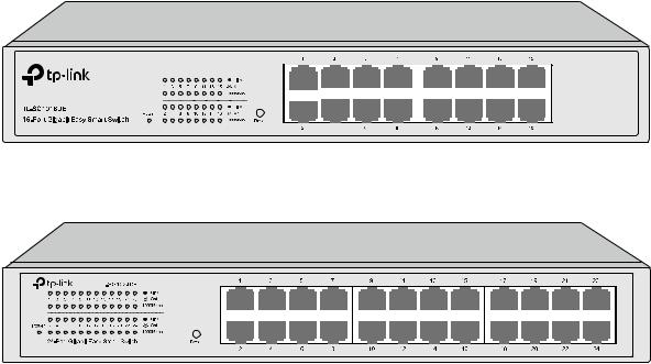
TL-SG1016DE/TL-SG1024DE
The front panel of TL-SG1016DE is shown as Figure 2-4.
Figure 2-4 Front Panel of TL-SG1016DE
The front panel of TL-SG1024DE is shown as Figure 2-5.
Figure 2-5 Front Panel of TL-SG1024DE
The following parts are located on the front panel of the switch:
Reset: With the switch powered on, press this button for five seconds or above to reset the software setting back to factory default setting.
1000Mbps Ports: Designed to connect to the device with a bandwidth of 10Mbps, 100Mbps or 1000Mbps. Each has a corresponding 1000Mbps LED and Link/Act LED.
LEDs
|
Name |
|
Status |
|
Indication |
|
Power |
|
On |
|
Power is on. |
|
|
Flashing |
|
Power supply is abnormal. |
|
|
|
|
Off |
|
Power is off or power supply is abnormal. |
|
|
|
|
7 |
|
|
Name |
|
|
Status |
|
|
Indication |
|
|
|||
|
1000Mbps |
|
|
On |
|
|
A 1000Mbps device is connected to the corresponding port. |
|||||
|
|
|
Off |
|
|
A 10/100Mbps device |
or |
no |
device is connected |
to |
the |
|
|
|
|
|
|
|
corresponding port. |
|
|
|
|
|
|
|
|
|
|
|
|
|
|
|
|
|
|
|
|
|
|
|
On |
|
|
A device is connected |
to |
the |
corresponding port |
but |
no |
|
|
|
|
|
|
activity. |
|
|
|
|
|
|
|
Link/Act |
|
|
|
|
|
|
|
|
|
|
|
|
|
|
Flashing |
|
|
Data is being transmitted or received. |
|
|
||||
|
|
|
|
|
|
|
|
|||||
|
|
|
|
Off |
|
|
No device is connected to the corresponding port. |
|
|
|||
TL_SG1016PE
The front panel of TL-SG1016PE is shown as Figure 2-6.
Figure 2-6 Front Panel of TL-SG1016PE
The following parts are located on the front panel of the switch:
Reset: With the switch powered on, press this button for five seconds or above to reset the software setting back to factory default setting.
1000Mbps Ports: Designed to connect to the device with a bandwidth of 10Mbps, 100Mbps or 1000Mbps. Each has a corresponding Speed LED. For Port 1– 8, each of them also has a PoE Status LED.
LEDs
|
Name |
|
|
Status |
|
|
Indication |
|
|
PWR |
|
|
|
On |
|
|
Power is on. |
|
|
|
Flashing |
|
|
Power supply is abnormal. |
||
|
|
|
|
|
Off |
|
|
Power is off or power supply is abnormal. |
|
|
|
|
On |
Green |
|
|
The corresponding port is running at 1000Mbps. |
|
Speed |
|
|
Yellow |
|
|
The corresponding port is running at 10/100Mbps. |
|
|
|
|
|
|
|
|||
|
|
|
Flashing |
|
|
The corresponding port is transmitting or receiving data. |
||
|
|
|
|
|
|
|||
|
|
|
|
|
Off |
|
|
There is no device linked to the corresponding port. |
|
|
|
|
|
On |
|
|
The port is connecting and supplying power to a PD. |
|
|
|
|
Flashing |
|
|
The PoE power circuit may be in short, the power current |
|
|
PoE Status |
|
|
|
|
may be overloaded or non-standard PD is connected. |
||
|
|
|
|
|
|
|
||
|
|
|
|
|
Off |
|
|
No PD is connected to the corresponding port, or no |
|
|
|
|
|
|
|
power is supplied according to the power limits of the port. |
|
|
|
|
|
|
|
|
|
|
|
|
|
|
|
|
8 |
||
|
Name |
|
|
Status |
|
|
Indication |
|
|
|
|
On |
|
|
The power of all the connected PoE ports is between |
|
|
|
|
|
|
103W and 110W. No power may be supplied if additional |
|
|
PoE Max |
|
|
|
|
|
PDs are connected. |
|
|
|
|
Flashing |
|
|
Thepowerof all theconnectedPoEports is ≥110W. |
|
|
|
|
Off |
|
|
The power of all the connected PoE ports is <103W. |
|
FAN |
|
|
Green |
|
|
The fan works properly. |
|
|
|
Yellow |
|
|
The fan doesn't work properly. |
|
|
|
|
|
|
|
2.2.2 Rear Panel
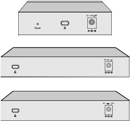
TL-SG105E/TL-SG108E/TL-SG108PE
The rear panel of TL-SG105E/TL-SG108E/TL-SG108PE features a power socket and a
Kensington Security Slot (marked with  ). TL-SG105E also has a Reset button located on the rear panel.
Figure 2-7 Rear Panel of TL-SG105E
Figure 2-8 Rear Panel of TL-SG108E
Figure 2-9 Rear Panel of TL-SG108PE
Reset: With the switch powered on, press this button for five seconds or above to reset the software setting back to factory default setting. (For TL-SG105E only)
Kensington Security Slot: Secure the lock (not provided) into the security slot to prevent the device from being stolen.
9

DC Power Socket: Connect the female connector of the power cord here, and the male connector to the DC power outlet. Please make sure the voltage of the power supply meets the requirement of the input voltage.
TL-SG1016DE/TL-SG1024DE/TL-SG1016PE
The rear panel of TL-SG1016DE/TL-SG1024DE/TL-SG1016PE features a power socket and a Grounding Terminal (marked with


 ). TL-SG1016PE also has a Kensington Security Slot (marked with
  ) located on the rear panel.
Figure 2-10 Rear Panel of TL-SG1016DE
Figure 2-11 Rear Panel of TL-SG1024DE
Figure 2-12 Rear Panel of TL-SG1016PE
Grounding Terminal: TL-SG105E/TL-SG108E/TL-SG108PE/TL-SG1016DE/TL-SG1024DE/ TL-SG1016PE already comes with Lightning Protection Mechanism. You can also ground the switch through the PE (Protecting Earth) cable of AC cord or with Ground Cable.
AC Power Socket: Connect the female connector of the power cord here, and the male connector to the AC power outlet. Please make sure the voltage of the power supply meets the requirement of the input voltage.
Kensington Security Slot: Secure the lock (not provided) into the security slot to prevent the device from being stolen.
Return to CONTENTS
10
Chapter 3 Log In to the Switch
3.1Login
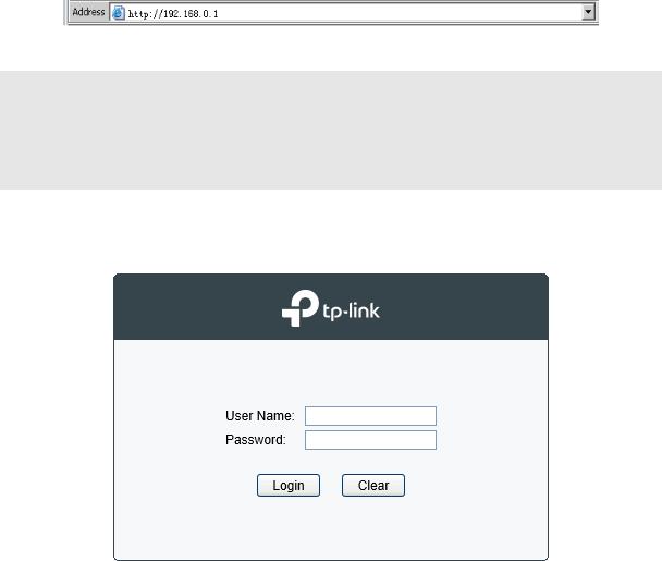
1)To access the configuration utility, open a web-browser and type the default address http://192.168.0.1 in the address field of the browser, then press the Enter key.
Figure 3-1 Web-browser
 Tips:
Tips:
To log in to the switch, the IP address of your PC should be set in the same subnet addresses of the switch. The IP address is 192.168.0.x ("x" is any number from 2 to 254), Subnet Mask is 255.255.255.0.
2)After a moment, a login window will appear, as shown in Figure 3-2. Enter admin for the User Name and Password, both in lower case letters. Then click the Login button or press the
Enter key.
Figure 3-2 Login
11
3.2 Configuration
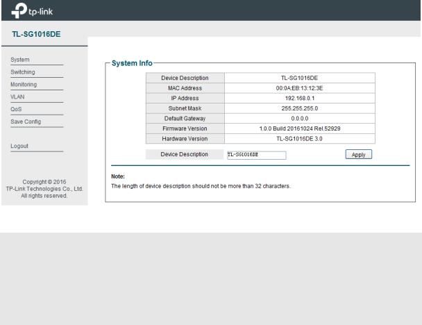
After a successful login, the main page will appear as Figure 3-3, and you can configure the function by clicking the setup menu on the left side of the screen.
Figure 3-3 Main Setup-Menu
 Note:
Note:
Clicking Apply can only make the new configurations effective before the switch is rebooted. If you want to keep the configurations effective even the switch is rebooted, please click Save Config. You are suggested to click Save Config before cutting off the power or rebooting the switch to avoid losing the new configurations.
Return to CONTENTS
12
Chapter 4 System
The System module is mainly for basic settings of the switch, including four submenus: System Info, IP Setting, User Account and System Tools.
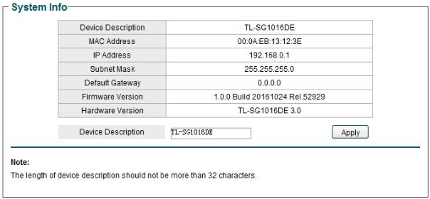
4.1 System Info
On this page you can view the system information and define the device description. Choose the menu System→System Info to load the following page.
Figure 4-1 System Info
The following entries are displayed on this screen:
System Info
Device Description: Displays the device model number. MAC Address: Displays the MAC address of the switch.
IP Address: Displays the system IP address of the switch. The default system IP is 192.168.0.1 and you can change it appropriate to your needs.
Subnet Mask: Displays the subnet mask of the switch. Default Gateway: Displays the default gateway of the switch. Firmware Version: Displays the installed software version number.
Hardware Version: Displays the installed device hardware version number. Device Description: Give a description to the device for identification.
4.2 IP Setting
Each device in the network possesses a unique IP Address. You can log on to the Web management page to operate the switch using this IP Address.
13
Loading...