


Enterprise Networking Solution
Installation Guide
L2 Managed Switch
TL-SG3210/TL-SG3216/TL-SG3424/TL-SG3424P

COPYRIGHT & TRADEMARKS
Specifications are subject to change without notice.  is a registered trademark of TP-LINK TECHNOLOGIES CO., LTD. Other brands and product names are trademarks of their respective holders.
No part of the specifications may be reproduced in any form or by any means or used to make any derivative such as translation, transformation, or adaptation without permission from TP-LINK TECHNOLOGIES CO., LTD. Copyright © 2013 TP-LINK TECHNOLOGIES CO., LTD. All rights reserved.
http://www.tp-link.com
FCC STATEMENT
This equipment has been tested and found to comply with the limits for a Class A digital device, pursuant to part 15 of the FCC Rules. These limits are designed to provide reasonable protection against harmful interference when the equipment is operated in a commercial environment. This equipment generates, uses, and can radiate radio frequency energy and, if not installed and used in accordance with the instruction manual, may cause harmful interference to radio communications. Operation of this equipment in a residential area is likely to cause harmful interference in which case the user will be required to correct the interference at his own expense.
This device complies with part 15 of the FCC Rules. Operation is subject to the following two conditions:
111 This device may not cause harmful interference.
222 This device must accept any interference received, including interference that may cause undesired operation.
Any changes or modifications not expressly approved by the party responsible for compliance could void the user’s authority to operate the equipment.
CE Mark Warning
This is a Class A product. In a domestic environment, this product may cause radio interference, in which case the user may be required to take adequate measures.
I  Copyright & Trademarks

Related Document
The User Guide and CLI Reference Guide of the product are provided on the resource CD.
To obtain the latest product information, please visit the official website:
http://www.tp-link.com
About this Installation Guide
This Installation Guide describes the hardware characteristics, installation methods and the points that should be attended to during installation.
This Installation Guide is structured as follows:
Chapter 1 Introduction. This chapter describes the external components of the switch.
Chapter 2 Installation. This chapter illustrates how to install the switch.
Chapter 3 Lightning Protection. This chapter illustrates how to prevent lightning damage.
Chapter 4 Connection. This chapter illustrates how to do the physical connection of the switch.
Chapter 5 Configuration. This chapter instructs you to configure the switch via Web Interface and CLI commands.
Appendix A Troubleshooting.
Appendix B Hardware Specifications.
Appendix C Technical Support.
Audience
This Installation Guide is for:
Network Engineer
Network Administrator
Conventions
Due to the similarity in structure of TP-LINK JetStream L2 Managed Switch series, in this Installation Guide we take TL-SG3216 as an example to illustrate Chapter 2 Installation, Chapter 3 Lighting Protection and Chapter 4 Connection.
This guide uses the specific formats to highlight special messages. The following table lists the notice icons that are used throughout this guide.
Remind to be careful. A caution indicates a potential which may result in device damage.
Remind to take notice. The note contains the helpful information for a better use of the product.
Related Document  II
II

Contents
Chapter 1 Introduction— ———————————— 01 |
||
1.1 |
Product Overview.......................................... |
01 |
1.2 |
Appearance.................................................. |
01 |
Chapter 2 Installation—————————————— 06 |
||
2.1 |
Package Contents......................................... |
06 |
2.2 |
Safety Precautions........................................ |
06 |
2.3 |
Installation Tools........................................... |
08 |
2.4 |
Product Installation....................................... |
08 |
Chapter 3 Lightning Protection— ———————— 10 |
||
3.1 |
Cabling Reasonably....................................... |
10 |
3.2 |
Connect to Ground........................................ |
12 |
3.3 |
Equipotential Bonding................................... |
13 |
3.4 |
Use Lightning Arrester................................... |
14 |
Chapter 4 Connection—————————————— 15 |
||
4.1 |
Ethernet Port................................................ |
15 |
4.2 |
SFP Port....................................................... |
15 |
4.3 |
Console Port................................................. |
16 |
4.4 |
Verify Installation.......................................... |
16 |
4.5 |
Power On ................................................... |
16 |
4.6 |
Initialization................................................. |
17 |
Chapter 5 Configuration———————————— 18 |
||
5.1 |
Configure the Switch via GUI......................... |
18 |
5.2 |
Configure the Switch Using CLI...................... |
19 |
Appendix A Troubleshooting——————————— 24 |
||
Appendix B Hardware Specifications——————— 25 |
||
Appendix C Technical Support—————————— 26 |
||
III  Contents


 L2 Managed Switch
CCCCCCCCCCCIntroduction
1111 Product Overview
TP-LINK JetStream L2 Managed Switch, designed for workgroups and departments, provides wire-speed performance and abundant layer 2 management features. It provides a variety of service features and multiple powerful functions with high security.
The EIA-standardized framework and smart configuration capacity can provide flexible solutions for a variable scale of networks. ACL, 802.1x and Dynamic ARP Inspection provide robust security strategies. QoS and IGMP snooping/filtering optimize voice and video application. Link aggregation (LACP\ increases aggregated bandwidth, optimizing the transport of business critical data. SNMP, RMON, WEB/CLI/Telnet Log-in bring abundant management policies. TP-LINK JetStream L2 Managed Switch integrates multiple functions with excellent performance, and is friendly to manage, which can fully meet the need of the users demanding higher networking performance.
TL-SG3424P Managed PoE Switch is also a Power Sourcing Equipment (PSE*\. All the Auto-Negotiation RJ45 ports on the switch support Power over Ethernet (PoE*\ function, which can automatically detect and supply power with those powered devices (PDs*\ complying with IEEE 802.3af and IEEE 802.3at.
*PSE: a device (switch or hub for instance\ that will provide power in a PoE setup.
*PoE: This technology describes a system to transmit electrical power, along with data, to remote devices over standard twisted-pair cable in an Ethernet.
*PD: a device powered by a PSE and thus consumes energy. Examples include powering IP telephones, wireless LAN access points, network cameras, network hubs, embedded computers etc.
1111 Appearance
■■ Front Panel
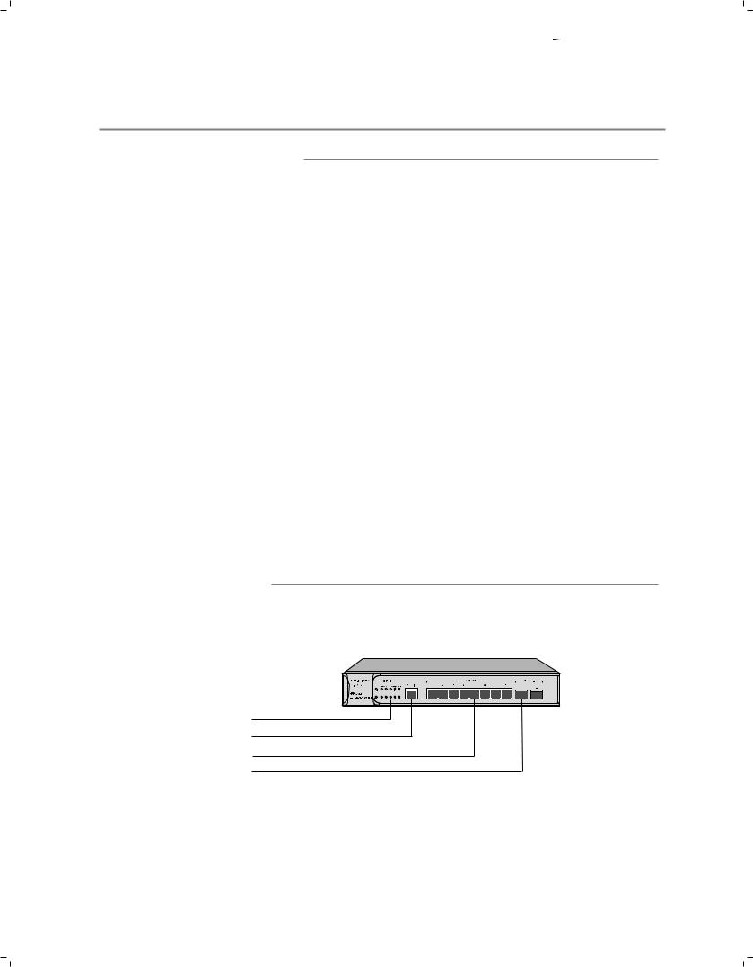
The front panel of TL-SG3210 is shown as the following figure.
LEDs |
Console Port |
10/100/1000Mbps RJ45 Port |
SFP Port
FFFFFFFFFFFFFront Panel of TL-SG3210
Introduction  01
01


 L2 Managed Switch
LEDs
LED |
Status |
Indication |
|
|
|
|
|
|
On |
The switch is powered on. |
|
|
|
|
|
PWR |
Off |
The switch is powered off or power supply is abnormal. |
|
|
|
|
|
|
Flashing |
Power supply is abnormal. |
|
|
|
|
|
SYS |
Flashing |
The switch works properly. |
|
|
|
||
On/Off |
The switch works improperly. |
||
|
|||
|
|
|
|
|
On |
A device is linked to the corresponding port. |
|
|
|
|
|
|
Flashing |
Data is being transmitted or received. |
|
|
|
|
|
10/100/1000M |
Green |
The linked device is running at 1000Mbps. |
|
|
|
|
|
|
Yellow |
The linked device is running at 10/100Mbps. |
|
|
|
|
|
|
Off |
No device is connected to the corresponding port. |
|
|
|
|
|
|
On |
A device is linked to the corresponding port. |
|
|
|
|
|
1000M |
Flashing |
Data is being transmitted or received. |
|
|
|
|
|
|
Off |
No device is connected to the corresponding port. |
|
|
|
|
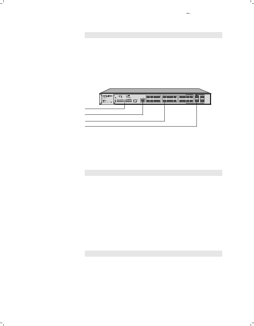
The front panel of TL-SG3216 is shown as the following figure.
Console Port |
LEDs |
10/100/1000Mbps RJ45 Port |
SFP Port
FFFFFFFFFFFFFront Panel of TL-SG3216
The front panel of TL-SG3424 is shown as the following figure.
21F |
23F |
Console Port |
LEDs |
10/100/1000Mbps RJ45 Port |
SFP Port |
FFFFFFFFFFFFFront Panel of TL-SG3424
LEDs
LED |
Status |
Indication |
|
|
|
|
|
|
On |
The switch is powered on. |
|
|
|
|
|
Power |
Off |
The switch is powered off or power supply is abnormal. |
|
|
|
|
|
|
Flashing |
Power supply is abnormal. |
|
|
|
|
|
System |
Flashing |
The switch works properly. |
|
|
|
||
On/Off |
The switch works improperly. |
||
|
|||
|
|
|
02  Introduction


 L2 Managed Switch
LED |
Status |
Indication |
|
|
|
|
|
|
On |
A 1000Mbps device is connected to the corresponding port. |
|
1000Mbps |
|
|
|
Off |
A 10/100Mbps device or no device is connected to the |
||
|
corresponding port. |
||
|
|
||
|
|
|
|
|
On |
A device is connected to the corresponding port, but no |
|
|
activity. |
||
Link/Act |
|
||
|
|
||
Flashing |
Data is being transmitted or received. |
||
|
|||
|
|
|
|
|
Off |
No device is connected to the corresponding port. |
|
|
|
|
The front panel of TL-SG3424P is shown as the following figure.
LEDs |
Console Port |
10/100/1000Mbps RJ45 Port |
SFP Port |
FFFFFFFFFFFFFront Panel of TL-SG3424P
TL-SG3424P has an LED mode switch button which is for switching the LED status indication. When the Speed LED is on, the port LED is indicating the data transmission rate. When the PoE LED is on, the port LED is indicating the power supply status. By default the Speed LED is on. Pressing the mode switch button, the Speed LED will turn off and the PoE LED will light up. Then the PoE LED will turn off after being on for 60 seconds and the Speed LED will light up again.
When the Speed LED is on, the port LED is indicating the data transmission rate.
LED |
Status |
|
Indication |
|
|
|
|
|
|
|
On |
|
The switch is powered on. |
|
|
|
|
|
|
Power |
Off |
|
The switch is powered off or power supply is abnormal. |
|
|
|
|
|
|
|
Flashing |
|
Power supply is abnormal. |
|
|
|
|
|
|
System |
Flashing |
|
The switch works properly. |
|
|
|
|
||
On/Off |
|
The switch works improperly. |
||
|
|
|||
|
|
|
|
|
|
|
On |
A 1000 Mbps device is connected to the corresponding |
|
|
Green |
port, but no activity. |
||
|
|
|||
10/100/ |
|
Flashing |
Data is being transmitted or received. |
|
|
|
|
||
|
On |
A 10/100 Mbps device is connected to the corresponding |
||
1000 Mbps |
|
|||
Yellow |
port, but no activity. |
|||
|
|
|||
|
|
|
||
|
|
Flashing |
Data is being transmitted or received. |
|
|
|
|
|
|
|
Off |
|
No device is connected to the corresponding port. |
|
|
|
|
|
When the PoE LED is on, the port LED is indicating the power supply status.
LED |
Status |
Indication |
|
|
|
|
|
|
On |
The switch is powered on. |
|
|
|
|
|
Power |
Off |
The switch is powered off or power supply is abnormal. |
|
|
|
|
|
|
Flashing |
Power supply is abnormal. |
|
|
|
|
|
System |
Flashing |
The switch works properly. |
|
|
|
||
On/Off |
The switch works improperly. |
||
|
|||
|
|
|
Introduction  03
03


 L2 Managed Switch
LED |
Status |
|
Indication |
|
|
|
|
|
|
|
On |
|
The remaining PoE power≤7W. |
|
|
|
|
|
|
PoE Max |
Flashing |
|
The remaining PoE power keeps ≤7W after this LED is |
|
|
on for 2 minutes. |
|||
|
|
|
||
|
Off |
|
The remaining PoE power≥7W. |
|
|
|
|
|
|
|
|
On |
The port is supplying power normally. |
|
|
Green |
|
|
|
|
Flashing |
The supply power exceeds the correponding port's |
||
|
|
|||
10/100/ |
|
maximum power. |
||
|
|
|
||
|
On |
Overload or short circuit is detected. |
||
1000 Mbps |
Yellow |
|||
|
|
|||
|
Flashing |
Power-on self-test has failed. |
||
|
|
|||
|
|
|
|
|
|
Off |
|
No PoE power supply is provided on the port. |
|
|
|
|
|
Note: TL-SG3216/TL-SG3424/TL-SG3424P switch features some “Combo” ports. A
“Combo” port consists of a RJ45 port and a SFP port, and the two ports share the same LED.
Port Feature
Model |
10/100/1000Mbps |
Console Port |
SFP Port |
|
RJ45 Port |
||||
|
|
|
||
|
|
|
|
|
TL-SG3210 |
8 |
1 |
2 |
|
|
|
|
|
|
TL-SG3216 |
16 |
1 |
2 |
|
|
|
|
|
|
TL-SG3424/TL-SG3424P |
24 |
1 |
4 |
|
|
|
|
|
10/100/1000Mbps Port
Designed to connect to the device with a bandwidth of 10Mbps, 100Mbps or 1000Mbps. Each has a corresponding 1000Mbps LED.
Console Port
Designed to connect with the serial port of a computer or terminal for monitoring and configuring the switch.
SFP Port
Designed to install the SFP module. TL-SG3216/TL-SG3424/TL-SG3424P switch features some SFP transceiver slots that are shared with the associated RJ45 ports. The associated two ports are referred as a “Combo” port, which means they cannot be used simultaneously, otherwise only SFP port works. TL-SG3210 features two individual SFP ports.
Note: For TL-SG3216/TL-SG3424/TL-SG3424P, when using the SFP port with a 100M module or a gigabit module, you need log on to the GUI (Graphical User
Interface) of the switch and configure its corresponding Speed and Duplex mode on
Switching→Port→Port Config page. For 100M module, please select 100MFD while select 1000MFD for gigabit module. By default, the Speed and Duplex mode of SFP port is 1000MFD. TL-SG3210 supports 1000M SFP module connection only.
■■ Rear Panel
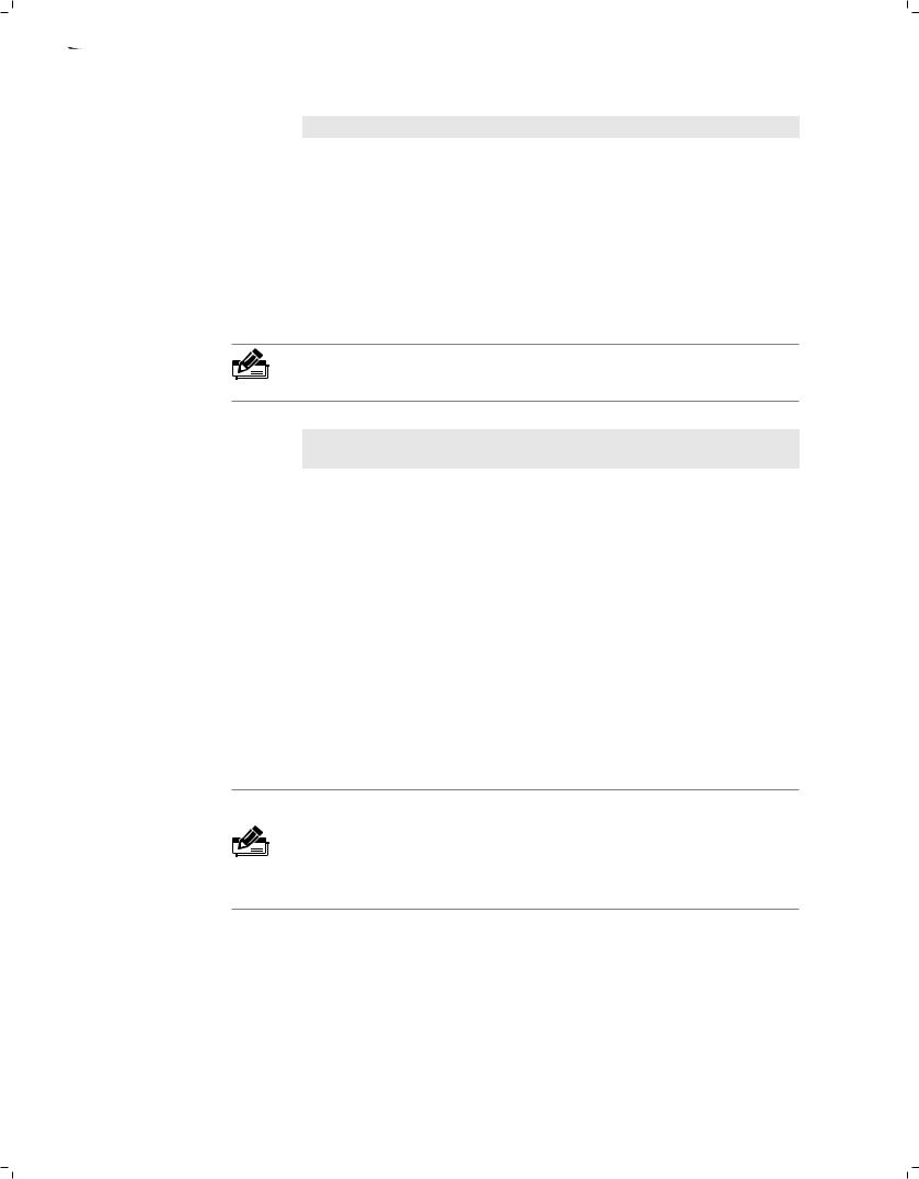
The rear panel of TL-SG3210 is shown as the following figure.
04  Introduction


 L2 Managed Switch
Grounding Terminal |
Power Socket |
FFFFFFFFFFFFRear Panel of TL-SG3210
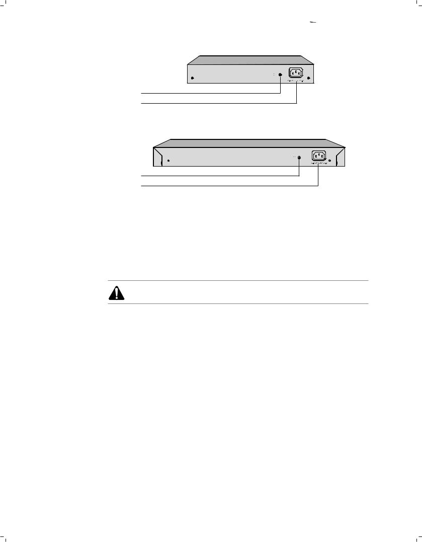
The rear panel of TL-SG3216/TL-SG3424/TL-SG3424P is shown as the following figure.
Grounding Terminal
Power Socket
FFFFFFFFFFFFRear Panel of TL-SG3216/TL-SG3424/TL-SG3424P
Grounding Terminal
The switch already comes with lightning protection mechanism. You can also ground the switch through the PE (Protecting Earth\ cable of AC cord or with Ground Cable. For detailed information, please refer to Chapter 3 Lightning Protection.
Power Socket
Connect the female connector of the power cord here, and the male connector to the AC power outlet. Please make sure the voltage of the power supply meets the requirement of the input voltage (100-240V~ 50/60Hz\.
Caution: Please use the provided power cord.
Introduction  05
05


 L2 Managed Switch
CCCCCCCCCCCInstallation
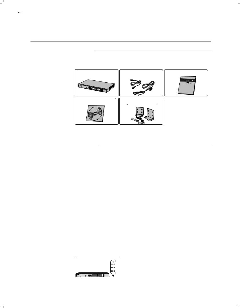
2222 Package Contents
Make sure that the package contains the following items. If any of the listed items is damaged or missing, please contact your distributor.
One Switch |
One Power Cord, One Console This Installation Guide |
|
Cable and one Ground Cable |
One Resource CD |
Two mounting brackets and |
|
the fittings |
2222Safety Precautions
To avoid any device damage and bodily injury caused by improper use, please observe the following rules.
■■ Safety Precautions
■■ Keep the power off during the installation.
■■ Wear an ESD-preventive wrist strap, and make sure that the wrist strap has a good skin contact and is well grounded.
■■ Use only the power cord provided with the switch.
■■ Make sure that the supply voltage matches the specifications indicated on the rear panel of the switch.
■■ Ensure the vent hole is well ventilated and unblocked. ■■ Do not open or remove the cover of the switch.
■■ Before cleaning the device, cut off the power supply. Do not clean it by the waterish cloth, and never use any other liquid cleaning method.
■■ Site Requirements
To ensure normal operation and long service life of the device, please install it in an environment that meets the requirements described in the following subsection.
Temperature/Humidity
06  Installation
 Loading...