


Enterprise Networking Solution
Installation Guide
Smart Switch
TL-SL2210/TL-SL2218/TL-SL2428/TL-SL2452

COPYRIGHT & TRADEMARKS
Specifications are subject to change without notice.  is a registered trademark of TP-LINK TECHNOLOGIES CO., LTD. Other brands and product names are trademarks of their respective holders.
No part of the specifications may be reproduced in any form or by any means or used to make any derivative such as translation, transformation, or adaptation without permission from TP-LINK TECHNOLOGIES CO., LTD. Copyright © 2013 TP-LINK TECHNOLOGIES CO., LTD. All rights reserved.
http://www.tp-link.com
FCC STATEMENT
This equipment has been tested and found to comply with the limits for a Class A digital device, pursuant to part 15 of the FCC Rules. These limits are designed to provide reasonable protection against harmful interference when the equipment is operated in a commercial environment. This equipment generates, uses, and can radiate radio frequency energy and, if not installed and used in accordance with the instruction manual, may cause harmful interference to radio communications. Operation of this equipment in a residential area is likely to cause harmful interference in which case the user will be required to correct the interference at his own expense.
This device complies with part 15 of the FCC Rules. Operation is subject to the following two conditions:
111 This device may not cause harmful interference.
222This device must accept any interference received, including interference that may cause undesired operation.
Any changes or modifications not expressly approved by the party responsible for compliance could void the user’s authority to operate the equipment.
CE Mark Warning
This is a class A product. In a domestic environment, this product may cause radio interference, in which case the user may be required to take adequate measures.
I  Copyright & Trademarks

Related Document
The User Guide is provided on the resource CD. To obtain the latest product information, please visit the official Website:
http://www.tp-link.com
About this Installation Guide
This Installation Guide describes the hardware characteristics, installation methods and the points that should be attended to during installation.
This Installation Guide is structured as follows:
Chapter 1 Introduction. This chapter describes the External Components of the Switch.
Chapter 2 Installation. This chapter illustrates how to install the switch.
Chapter 3 Lightning Protection. This chapter illustrates how to prevent lightning damage.
Chapter 4 Connection. This chapter illustrates how to do the physical connection of the switch.
Chapter 5 Login to the Switch. This chapter instructs you to login to the switch via Web Interface.
Appendix A Troubleshooting. Appendix B Hardware Specifications. Appendix C Technical Support.
Related Document  II
II
Audience
This Installation Guide is for:
Network Engineer
Network Administrator
Conventions
Due to the similarity in structure of TL-SL2210/TL-SL2218/TL-SL2428/TL-SL2452 Smart Switch, in this Installation Guide we take TL-SL2218 as an example to illustrate Chapter 2 Installation, Chapter 3 Lightning Protection, Chapter 4 Connection and Chapter 5 Login to the Switch.
This Guide uses the specific formats to highlight special messages. The following table lists the notice icons that are used throughout this guide.
Remind to be careful. A caution indicates a potential which may result in device damage.
Remind to take notice. The note contains the helpful information for a better use of the product.
III  Audience

Contents
Chapter 1 |
Introduction—————————————— 01 |
|
1.1 |
Product Overview.......................................... |
01 |
1.2 |
Appearance.................................................. |
01 |
Chapter 2 |
Installation— —————————————— 05 |
|
2.1 |
Package Contents......................................... |
05 |
2.2 |
Safety Precautions........................................ |
05 |
2.3 |
Installation Tools........................................... |
07 |
2.4 |
Product Installation....................................... |
08 |
Chapter 3 |
Lightning Protection——————————— 10 |
|
3.1 |
Cabling Reasonably....................................... |
10 |
3.2 |
Connect to Ground........................................ |
12 |
3.3 |
Equipotential Bonding.................................... |
13 |
3.4 |
Use Lightning Arrester................................... |
14 |
Chapter 4 |
Connection— —————————————— 16 |
|
4.1 |
Ethernet Port................................................ |
16 |
4.2 |
SFP Port....................................................... |
16 |
4.3 |
Verify Installation.......................................... |
17 |
4.4 |
Power On..................................................... |
17 |
4.5 |
Initialization.................................................. |
17 |
Chapter 5 Login to the Switch— —————————— 18 Appendix A Troubleshooting————————————— 19
Appendix B Hardware Specifications————————— 20
Appendix C Technical Support———————————— 21
Contents  IV
IV

Smart Switch
CCCCCCCCCC Introduction
1111 Product Overview
TL-SL2210/TL-SL2218/TL-SL2428/TL-SL2452 is compliant with the IEEE802.3 Ethernet protocols.
These switches are equipped with powerful management interface, via which system, port, network, VLAN and priority can be configured. They provide a variety of service features and multiple powerful functions with high security. The EIA-standardized framework and smart configuration capacity can provide flexible solutions for a variable scale of networks. QoS and IGMP snooping/filtering optimize voice and video application. SNMP, RMON, WEB Log-in bring abundant management policies.
TL-SL2210/TL-SL2218/TL-SL2428/TL-SL2452 integrates multiple functions with excellent performance, and are friendly to manage, which can fully meet the need of the users demanding higher networking performance.
1111 Appearance
■■ Front Panel
The front panel of TL-SL2210 is shown as Figure 1-1.
LEDs
Reset
10/100Mbps RJ45 Port
10/100/1000Mbps RJ45 Port SFP Port
FFFFFFFFFFFFront Panel of TL-SL2210
The front panel of TL-SL2218 is shown as Figure 1-2.
LEDs |
Reset |
10/100Mbps RJ45 Port |
10/100/1000Mbps RJ45 Port |
SFP Port
FFFFFFFFFFFFront Panel of TL-SL2218
The front panel of TL-SL2428 is shown as Figure 1-3.
01  Introduction

Smart Switch
LEDs |
Reset |
10/100Mbps RJ45 Port |
10/100/1000Mbps RJ45 Port |
SFP Port |
FFFFFFFFFFFFront Panel of TL-SL2428
The front panel of TL-SL2452 is shown as Figure 1-4.
RESET
LEDs
10/100Mbps RJ45 Port
10/100/1000Mbps RJ45 Port
SFP Port
FFFFFFFFFFFFront Panel of TL-SL2452
LEDs
LED |
Status |
Indication |
|
|
|
|
On(green1 |
The switch is powered on |
Power |
|
|
Off/ |
The switch is powered off or power supply |
|
|
Flashing |
is abnormal |
|
|
|
|
Flashing |
The switch works properly |
System |
|
|
On/Off |
The switch is powered off or the switch |
|
|
works improperly |
|
|
|
|
|
|
|
|
On |
A device is linked to the corresponding port |
10/100M |
|
|
Flashing |
Data is being transmitted or received |
|
|
|
|
(10/100Mbps1 |
Green |
The linked device is running at 100Mbps |
|
|
|
|
Yellow |
The linked device is running at 10Mbps |
|
|
|
|
On |
A device is linked to the corresponding port |
1000M |
|
|
Flashing |
Data is being transmitted or received |
|
|
|
|
(1000Mbps1 |
Green |
The linked device is running at 1000Mbps |
|
|
|
|
Yellow |
The linked device is running at 10/100Mbps |
|
|
|
Introduction  02
02
Smart Switch
Port Feature
Model |
10/100Mbps RJ45 Port |
10/100/1000Mbps RJ45 Port |
SFP Port |
|
|
|
|
TL-SL2210 |
8 |
1 |
1 |
|
|
|
|
TL-SL2218 |
16 |
2 |
2(Combo1 |
|
|
|
|
TL-SL2428 |
24 |
4 |
2(Combo1 |
|
|
|
|
TL-SL2452 |
48 |
2 |
2 |
|
|
|
|
Reset(RESET)
With the switch powered on, press Reset button for five seconds to reset the software setting to its factory default settings.
10/100Mbps RJ45 Port
Designed to connect to the device with a bandwidth of 10Mbps or 100Mbps. Each has a corresponding 10/100M LED.
10/100/1000Mbps RJ45 Port
Designed to connect to the device with a bandwidth of 10Mbps, 100Mbps or 1000Mbps. Each has a corresponding 1000M LED.
SFP Port
Designed to install the SFP module. TL-SL2218/TL-SL2428 features some SFP transceiver slots that are shared with the associated RJ45 ports. The associated two ports are referred as a "Combo" port, which means they cannot be used simultaneously, otherwise only SFP port works. Meanwhile, the associated two ports share the same LED. For TL-SL2218, Port 17 shares the same LED with Port 17F and Port 18 shares the same LED with Port 18F; for TL-SL2428 Port 27 shares the same LED with Port 27F and Port 28 shares the same LED with Port 28F.
■■ Rear Panel
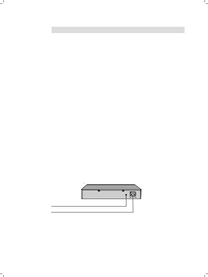
The rear panel of TL-SL2210 is shown as Figure 1-5.
Grounding Terminal
Power Socket
FFFFFFFFFFFFRear Panel of TL-SL2210
03  Introduction
Smart Switch
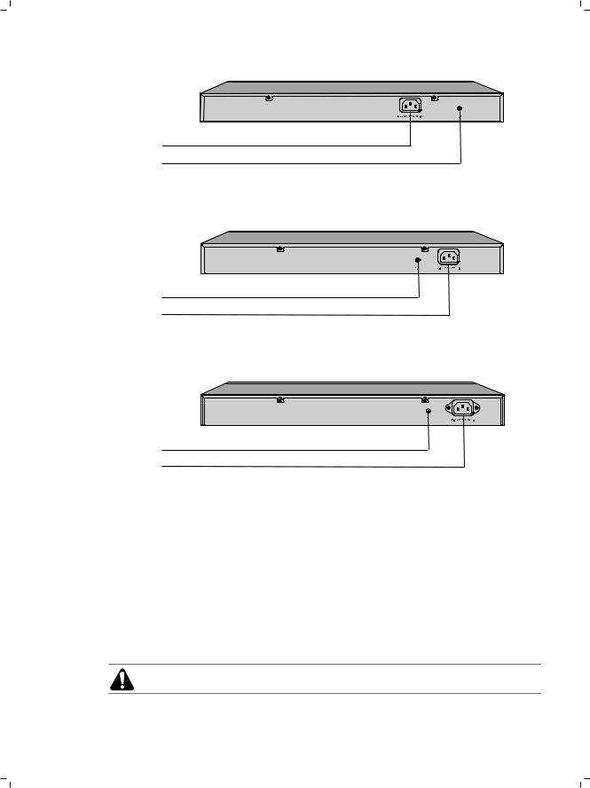
The rear panel of TL-SL2218 is shown as Figure 1-6.
Power Socket
Grounding Terminal
FFFFFFFFFFFFRear Panel of TL-SL2218
The rear panel of TL-SL2428 is shown as Figure 1-7.
Grounding Terminal
Power Socket
FFFFFFFFFFFFRear Panel of TL-SL2428
The rear panel of TL-SL2452 is shown as Figure 1-8.
Grounding Terminal
Power Socket
FFFFFFFFFFFFRear Panel of TL-SL2452
Power Socket
Connect the female connector of the power cord here, and the male connector to the AC power outlet. Please make sure the voltage of the power supply meets the requirement of the input voltage.
Grounding Terminal
The switch already comes with lightning protection mechanism. You can also ground the switch through the PE (Protecting Earth\ cable of AC cord or with Ground Cable. For detailed information, please refer to Chapter 3 Lightning Protection.
Caution: Please use the provided power cord.
Introduction  04
04
 Loading...