


Sony RM-932, RM-887, KV-29LS35K, KV-29LS35E, KV-29LS35B Service Manual
...SERVICE MANUAL |
FE-2 CHASSIS |
|
|
|
|
MODEL |
COMMANDER DEST CHASSIS NO. MODEL |
COMMANDER DEST CHASSIS NO. |
KV-29LS30E KV-29LS30K KV-29LS30U
RM-887 ESP SCC-Q53F-A
RM-887 OIRT SCC-Q51G-A
RM-887 UK SCC-Q52F-A
KV-29LS35B KV-29LS35E KV-29LS35K
RM-932 |
FR |
SCC-Q54F-G |
RM-932 |
ESP SCC-Q53G-A |
|
RM-932 |
OIRT |
SCC-Q51H-A |
RM-889
RM-887
RM-932
1
FE-2 SELF DIAGNOSTIC SOFTWARE
The identification of errors within the FE-2 chassis is triggered in one of two ways :- 1: Busy or 2: Device failure to respond to IIC. In the event of one of these situations arising the software will first try to release the bus if busy (Failure to do so will report with a continuous flashing LED) and then communicate with each device in turn to establish if a device is faulty. If a device is found to be faulty the relevant device number will be displayed through the LED (Series of flashes which must be counted) See table 1., non fatal errors are reported using this method.
Each time the software detects an error it is stored within the NVM. See Table 2.
Table 1
Error Message |
LED |
|
Code |
||
|
||
No error |
00 |
|
Reserved |
01 |
|
OCP ( Over Current Protection ) |
02 |
|
Not Used |
03 |
|
No Vertical Sync |
04 |
|
IKR Error at power on |
05 |
|
IIC bus clock and/or data lines low at power on |
06 |
|
NVM no IIC bus acknowledge at power on |
07 |
|
Not Used |
08 |
|
Tuner no acknowledge at power on |
09 |
|
Sound Processor Error |
10 |
|
|
|
|
Jungle controller 8 volts error |
11 |
|
|
|
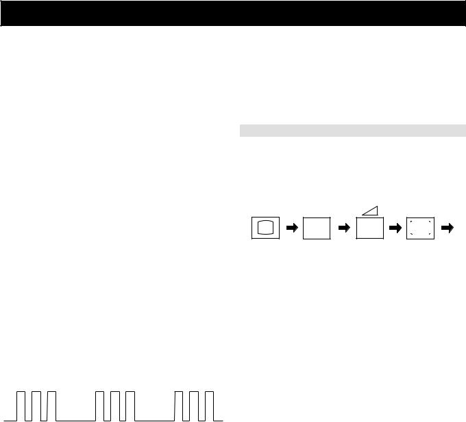
Flash Timing Example : e.g. error number 3
StBy LED
ON |
ON |
ON |
|
OFF |
OFF |
How to enter into Table 2
1.Turn on the main power switch of the TV set and enter into the
‘Stanby Mode’.
2.Press the following sequence of buttons on the Remote Commander.
i+ |
5 |
- |
|
(ON SCREEN |
(DIGIT 5) |
(VOLUME -) |
(TV) |
DISPLAY) |
|
|
|
3.The following table will be displayed indicating the error count.
Table 2
ERROR MENU |
|
|
|
E02 |
OCP |
(0, 255) |
0 |
E03 |
OVP N/A |
(0, 255) |
0 |
E04 |
VSYNC |
(0, 255) |
0 |
E05 |
IKR |
(0, 255) |
0 |
E06 |
IIC |
(0, 255) |
0 |
E07 |
NVM |
(0, 255) |
0 |
E08 |
JUNGLE |
(0, 255) |
0 |
E09 |
TUNER |
(0, 255) |
0 |
E10 |
SOUNDP |
(0, 255) |
0 |
E11 |
8V |
(0, 255) |
0 |
WORKING TIME |
|
|
|
HOURS |
|
|
2 |
MINUTES |
|
|
11 |
|
|
|
|
Note: To clear the error count data press ‘80’ on the Remote commander.
6

C Board Waveforms
C board Waveforms
TP1 |
10us/div |
TP2 |
20us/div |
TP3 |
20us/div |
|
|
||||
1.77 Vp-p (H) |
|
1.88 Vp-p (H) |
|
1.88 Vp-p (H) |
|
|
20us/div |
|
|
|
|
TP4 |
|
TP5 |
20us/div |
TP6 |
20us/div |
|
|
|
|||
74 Vp-p (H) |
|
74 Vp-p (H) |
|
74 Vp-p (H) |
|
TP7 |
20us/div |
|
|
|
|
|
|
|
|
|
|
1.76 Vp-p (H) |
|
|
|
|
|
IC Voltage Table
Ref No |
Pin No |
Voltage (V) |
Ref No |
Pin No |
Voltage (V) |
|
|
|
|
|
|
|
|
|
1 |
3.1 |
|
1 |
1.3 |
|
|
|
|
|
|
|
|
|
2 |
2.1 |
|
2 |
1.3 |
|
|
|
|
|
|
|
|
|
3 |
3.0 |
|
3 |
1.4 |
|
IC1701 |
|
|
IC1801 |
|
|
|
5 |
5.5 |
5 |
4.1 |
|
||
|
|
|
||||
|
|
|
|
|
|
|
|
7 |
131 |
|
6 |
4.1 |
C [ R,G,B OUT ] |
|
8 |
123 |
|
7 |
7.0 |
|
|
|
|
|
|
|
|
|
9 |
124.6 |
|
8 |
8.0 |
|
|
|
|
|
|
|
|
27 |
28 |
 Loading...