


4-696-257-11(1)
Remote Controller
Operating Instructions
Before operating the unit, please read this manual thoroughly and retain it for future reference.
RM-IP500
© 2017 Sony Corporation

Table of Contents |
|
Introduction |
|
Using This Manual ................................................ |
4 |
Features .................................................................. |
4 |
Location and Function of Parts ............................ |
5 |
Top ..................................................................... |
5 |
Rear .................................................................. |
10 |
Side / front ........................................................ |
11 |
Menu Operations ................................................. |
12 |
Basic menu operations ..................................... |
12 |
Getting Started |
|
Connections .......................................................... |
14 |
VISCA over IP (LAN) connection ................... |
14 |
VISCA RS-422 (serial) connection .................. |
21 |
Connection with a video switcher .................... |
24 |
Using a Setup PC ................................................. |
25 |
Accessing a remote controller .......................... |
25 |
Saving configuration data on a PC (Backup) ... |
25 |
Loading a saved configuration file into the |
|
unit or another remote controller (Restore) .... |
26 |
About the RM-IP Setup Tool ........................... |
26 |
Operations |
|
Turning on the Power .......................................... |
27 |
Selecting a Camera .............................................. |
27 |
Selecting a camera when using LAN |
|
connection ...................................................... |
27 |
Selecting a camera when using serial |
|
connection ...................................................... |
28 |
About the color of camera buttons ................... |
28 |
About the tally lamp indicators ........................ |
28 |
Operating a Camera ............................................ |
29 |
Pan and tilt control ........................................... |
29 |
Zoom control .................................................... |
30 |
Adjusting a Camera ............................................ |
31 |
Adjusting the focus .......................................... |
31 |
Adjusting the brightness ................................... |
31 |
Backlight compensation ................................... |
32 |
Flicker compensation ....................................... |
32 |
Adjusting the white balance ............................. |
32 |
Adjusting the black balance ............................. |
33 |
Storing the Camera Status (Preset Function) ... |
34 |
Recalling stored status ..................................... |
34 |
Changing the speed of movement between |
|
positions ......................................................... |
34 |
Operating the Camera Setup Menu from the Unit |
|
(Camera Menu Operation Mode) ...................... |
35 |
Buttons and knobs used for camera menu |
|
operations ....................................................... |
35 |
Setting Specific Functions using Shortcuts |
|
(FUNCTION Menu) ........................................... |
37 |
Buttons and knobs used for FUNCTION menu |
|
operations ....................................................... |
37 |
Operation using IRIS, GAIN, and SHUTTER |
|
buttons ........................................................... |
37 |
Operation using ASSIGN 4, ASSIGN 5, and |
|
ASSIGN 6 ...................................................... |
38 |
Checking Camera Settings Status (Status |
|
Display) ................................................................ |
38 |
Restoring Factory Default Settings ................... |
39 |
Default values .................................................. |
39 |
Function of Buttons/Knobs in Each Block by |
|
Camera Model ..................................................... |
41 |
RM Menu List |
|
OPERATION ....................................................... |
43 |
EXPOSURE ..................................................... |
43 |
WHITE ............................................................ |
43 |
BLACK ............................................................ |
44 |
DETAIL ........................................................... |
44 |
KNEE ............................................................... |
44 |
MATRIX .......................................................... |
44 |
PRESET ........................................................... |
44 |
OPERATION menu support by camera |
|
model ............................................................. |
45 |
CONFIG .............................................................. |
46 |
RM SETUP ...................................................... |
46 |
SW ASSIGN .................................................... |
46 |
DIRECTION .................................................... |
46 |
GPI I/O ............................................................ |
47 |
LAN ................................................................. |
48 |
SERIAL ........................................................... |
48 |
CONTROL I/F ................................................. |
48 |
AUTO IP SETUP ................................................ |
48 |
SETUP IP ........................................................ |
48 |
ASSIGN CAM ................................................. |
48 |
CLEAR TABLE ............................................... |
48 |
SWAP CAM .................................................... |
48 |
CAMERA TABLE ........................................... |
48 |
MAINTENANCE ................................................ |
49 |
MODEL INFO ................................................. |
49 |
UPDATE MODE ............................................. |
49 |
RESET ............................................................. |
49 |
Appendix |
|
Troubleshooting ................................................... |
50 |
Specifications ....................................................... |
51 |
Dimensions ...................................................... |
51 |
2

Pin assignments ................................................ |
52 |
TALLY/CONTACT connector input connection |
|
example .......................................................... |
53 |
TALLY/CONTACT connector output connection |
|
example .......................................................... |
53 |
Input waveform of TALLY/CONTACT |
|
connector ........................................................ |
53 |
License .................................................................. |
54 |
•Microsoft and Windows are registered trademarks of Microsoft Corporation in the United States and/ or other countries.
•Intel and Core are registered trademarks of Intel Corporation or its subsidiaries in the United States and other countries.
All other company and product names are trademarks or registered trademarks of the respective companies or their respective makers. Trademarked items are not indicated by ® or ™ symbols in this manual.
Data and security
•SONY WILL NOT BE LIABLE FOR DAMAGES OF ANY KIND RESULTING FROM A FAILURE TO IMPLEMENT PROPER SECURITY MEASURES ON TRANSMISSION DEVICES, UNAVOIDABLE DATA LEAKS RESULTING FROM TRANSMISSION SPECIFICATIONS, OR SECURITY PROBLEMS OF ANY KIND.
•Depending on the operating environment, unauthorized third parties on the network may be able to access the unit. When connecting the unit to the network, be sure to confirm that the network is protected securely.
•Do not browse any other website in the Web browser while making settings or after making settings. Since the login status remains in the Web browser, close the Web browser when you complete the settings to prevent unauthorized third parties from using the unit or harmful programs from running.
3

Introduction
Safety Regulations (Supplied)
Describes the important points for safe use of the unit. Be sure to read it.
Operating Instructions (This document/ Web)
These operating instructions describe the names of the various parts of the unit, installation, connection, and operation methods.
Using This Manual
The Operating Instructions is designed to be read on a computer display.
The content you need to know in order to use the unit is described here.
Read it before you operate the unit.
Jumping to a related page
When you read the instructions on a computer display and click on the related part of the relevant page that is being displayed, you jump to the related page. Relevant pages can be searched easily.
Software display examples
The software displays described in this manual are explanatory examples. Note that some displays may be different from the ones that actually appear.
Printing the Operating Instructions
Depending on your system, certain displays or illustrations in the Operating Instructions, when printed out, may differ from those that appear on your screen.
Terminology in this document
The RM-IP500 is referred to as the “unit” or “remote controller” in this document.
Features
This unit is a remote controller that provides the full functionality and operability of Sony PTZ cameras.
Simple system construction
The unit can be used to control up to 100 cameras connected via LAN connection using switching hubs. You can build a system, using the setup functions of the unit, to set the IP address and camera number of multiple cameras in a single step, without using a setup PC.
Functional design
The buttons and knobs of the control panel are grouped by type of operation for easy operation. For example, the buttons and knobs for making color adjustments on a camera are grouped together in the color adjustment block.
Compact size
The unit has a compact size for mounting on a desktop. It can also be mounted in a console desk.
Flexible camera operation for various use cases
You can adjust the pan, tilt, and zoom of the camera image with one hand using a joystick. The zoom operation can also be controlled using a zoom lever, enabling detailed camera control using both hands. The speed of pan, tilt, and zoom can also be adjusted using a speed adjustment knob.
Preset memory function
You can save camera settings, such as pan/tilt/zoom positions and other camera adjustment settings, in the memory of the camera. The stored settings can be recalled and applied to the camera by pressing a preset number button assigned when storing settings.
Simple operation of various camera adjustments
Using the buttons on the unit, you can quickly control various camera functions, such as auto focusing, onepush auto focus, AE (Auto Exposure) function, onepush auto white balance, and backlight compensation, without having to access the camera menu.
4

Location and Function of Parts
The functions controlled by the buttons and knobs vary depending on the target camera to control. For details, see “Function of Buttons/Knobs in Each Block by Camera Model” (page 41).
Top
Color adjustment |
Menu control |
|
|
Camera selection |
|||
block (page 5) |
block (page 6) |
|
|
block (page 7) |
|||
|
|
|
|
|
|
|
|
|
|
|
|
|
|
|
|
Lens control block |
Preset memory control |
Joystick control block |
(page 7) |
block (page 8) |
(page 9) |
Color adjustment block
Use to perform color adjustments on a camera. Select the target camera to adjust the color. The color adjustment block is enabled when the 7 ACTIVE button is lit.
For details about selecting the target camera, see “Selecting a Camera” (page 27).
4 5 6 7
3


 8 2-b
8 2-b
2-a
1-c
1-b
1-a
5

A1-a R-BLACK knob
1-b B-BLACK knob
1-c MASTER BLACK knob
Adjusts the R black, B black, and master black of the target camera.
For details, see “Adjusting the black balance” (page 33).
B2-a R-WHITE knob
2-b B-WHITE knob
Sets the R gain and B gain of the target camera, and adjusts the white balance.
For details, see “Adjusting the white balance” (page 32).
CBARS button
Toggles the color bars output of the target camera on/off.
When the button is turned on (button is lit yellow), color bars output is turned on.
When the button is turned off (button is not lit), color bars are not output.
DCAM POWER button
Toggles the power supply of the target camera on/ off (standby).
When the button is turned on (button is lit green), the target camera is turned on.
When the button is turned off (button is not lit), the target camera is turned off (standby).
Note
When controlling more than one camera, the camera on/off operation is determined by the CONFIG >RM SETUP >CAM POWER setting in the RM menu. For details, see “CAM POWER” (page 46).
EO.P.AWB (one-push auto white balance) button
Executes one-push auto white balance adjustment on the target camera.
For details, see “To adjust the white balance automatically” (page 32).
FO.P.ABB (one-push auto black balance) button
Executes one-push auto black balance adjustment on the target camera.
For details, see “To adjust the black balance automatically” (page 33).
GACTIVE button
Enables/disables the color adjustment block. When the button is turned on (button is lit), the color adjustment block becomes enabled.
When the button is turned off (button is not lit), the color adjustment block becomes disabled.
HASSIGN 1 button, ASSIGN 2 button, ASSIGN 3 button
Executes functions assigned to each button on the target camera.
In this version, the following functions have been assigned, and cannot be changed.
Button name |
Assigned function |
|
|
ASSIGN 1 |
Perform backlight compensation on the |
|
target camera. For details, see |
|
“Backlight compensation” (page 32). |
|
|
ASSIGN 2 |
Perform flicker compensation on the |
|
target camera. For details, see “Flicker |
|
compensation” (page 32). |
|
|
ASSIGN 3 |
Display the iris, gain, shutter speed, and |
|
zoom position settings of the target |
|
camera on the LCD panel. For details, |
|
see “Checking Camera Settings Status |
|
(Status Display)” (page 38). |
|
|
Menu control block
Comprises buttons and knobs you use to set and execute functions, and to change settings on the target camera using menu operations.
For details about menu operations, see “Menu Operations” (page 12).
2
3
4
5


 6 1
6 1


7
AFUNCTION menu buttons
When a button is pressed, the item and setting of the function assigned to the button is displayed on the LCD panel, and the setting can be changed using the VALUE knob.
The IRIS, GAIN, and SHUTTER button operations are enabled when the buttons are lit blue.
For details about operation, see “Setting Specific Functions using Shortcuts (FUNCTION Menu)” (page 37).
IRIS button: Press this button to display the iris value settings screen for the camera on the LCD panel.
6

GAIN button: Press this button to display the gain value settings screen for the camera on the LCD panel.
SHUTTER button: Press this button to display the shutter speed value settings screen for the camera on the LCD panel.
ASSIGN 4 button, ASSIGN 5 button, ASSIGN 6 button: Press these buttons to display the corresponding setup item and setting of the function assigned to each button on the LCD panel.
In this version, the following functions have been assigned, and cannot be changed.
Button name |
Assigned menu item |
|
|
ASSIGN 4 |
Sets DETAIL LEVEL on the target |
|
camera. |
|
|
ASSIGN 5 |
Sets KNEE POINT on the target |
|
camera. |
|
|
ASSIGN 6 |
Sets AE LEVEL on the target camera. |
|
|
For details about menu operations, see “Menu Operations” (page 12).
BLCD panel
Displays the RM menu, FUNCTION menu, and preset memory numbers.
•For details about menu operations, see “Menu Operations” (page 12).
•For details about the RM menu, see “RM Menu List” (page 43).
•For details about the FUNCTION menu, see “Setting Specific Functions using Shortcuts (FUNCTION Menu)” (page 37).
•For details about preset numbers, see “Storing the Camera Status (Preset Function)” (page 34).
CSELECT knob and button
Use to select menu items.
For details about menu operations, see “Menu Operations” (page 12).
DVALUE knob and button
Use to select the settings of menu items.
For details about menu operations, see “Menu Operations” (page 12).
ECANCEL button
Use to move from a lower level to a higher level in the hierarchy for menu items that have a multi-level hierarchy.
FRM MENU button
Press this button to display the setup menu of the unit on the LCD panel.
For details about menu operations, see “Menu Operations” (page 12).
GCAM MENU button
Press and hold this button to display the setup menu of the camera on the monitor output of the camera. Nothing is displayed on the LCD panel of the unit. For details about operation, see “Operating the Camera Setup Menu from the Unit (Camera Menu Operation Mode)” (page 35).
Camera selection block
Use to select the target camera to control.
When using LAN connection, the unit can control up to 100 cameras.
When using serial connection, the unit can control up to 7 cameras.

 2
2
1
ACAMERA 1 to CAMERA 10 buttons
Selects the target camera from within a group. For details about selecting the target camera, see “Selecting a Camera” (page 27).
BGROUP LEFT button, group number display, GROUP RIGHT button
Select the target camera group using the GROUP LEFT button and GROUP RIGHT button. The number of the selected group is displayed in the group number display.
Group numbers are used with LAN connections. For details about selecting a group, see “Selecting a Camera” (page 27).
Lens control block
Use to control the lens (adjustment and settings) of the target camera.
The lens control block is enabled when the 5 ACTIVE button is lit. Note that the ZOOM SPEED knob is always enabled.
7

3 4
5
2
 6
6
7
1
8
9
AIRIS knob
Adjusts the iris of the target camera.
For details, see “To adjust the exposure manually” (page 31).
BAE button
Switches the exposure mode of the target camera. When the button is turned on (button is lit), auto adjustment mode is selected. When the button is turned off (button is not lit), the exposure mode set in the RM menu is selected.
For details, see “To adjust the exposure automatically” (page 31).
CZOOM SPEED knob
Sets the speed of zoom operations.
For details, see “To control the zoom using the ZOOM lever on the lens control block” (page 30).
DZOOM lever
Controls the zoom operation of the target camera. For details, see “To control the zoom using the ZOOM lever on the lens control block” (page 30).
EACTIVE button
Enables/disables the lens control block.
When the button is pressed, turning it on (button is lit), the lens control block becomes enabled. When the button is turned off (button is not lit), the lens control block becomes disabled.
FFOCUS SPEED knob
Sets the focus speed when adjusting the focus manually.
For details, see “To adjust the focus manually” (page 31).
GAUTO FOCUS mode button
Switches between automatic (button is lit) and manual (button is not lit) focus adjustment mode on the target camera.
For details, see “To adjust the focus automatically” (page 31).
HO.P.A.F (one-push auto focus) button
Press during manual focus adjustment mode to execute one-push auto adjustment.
For details, see “One-push auto focus during manual focus adjustment” (page 31).
IFOCUS adjustment knob
Adjusts the focus of the target camera manually. For details, see “To adjust the focus manually” (page 31).
Preset memory control block
Use to execute the Preset function for storing and recalling camera status (such as pan, tilt, zoom position settings) in internal memory on the camera.
The preset memory control block is enabled when the 4 ACTIVE button is lit.
Note
The number of presets varies depending on the model and firmware version of the camera. For details, refer to the Operating Instructions supplied with the camera.
2 3 4
1
5
6
APRESET 1 button to PRESET 10/0 button
Use to enter the number (preset number) for registering and recalling a preset camera status. For details, see “Storing the Camera Status (Preset Function)” (page 34).
8

BDIRECT RECALL button
Recalls a preset stored in the target camera. Direct recall mode is enabled when the button is lit. Press PRESET 1 to PRESET 10/0 to recall the stored settings immediately.
For details, see “Storing the Camera Status (Preset Function)” (page 34).
CCLEAR button
Clears the currently entered preset number.
DACTIVE button
Enables/disables operation of the preset memory control block.
When the button is turned on (button is lit), the preset memory control block becomes enabled. When the button is turned off (button is not lit), the preset memory control block becomes disabled.
ESTORE button
Stores the camera status in the internal memory of the camera for the specified preset number.
For details, see “Storing the Camera Status (Preset Function)” (page 34).
FRECALL button
Recalls a preset stored in the target camera.
For details, see “Recalling stored status” (page 34).
Joystick control block
Use to control the pan, tilt, and zoom of the target camera using a joystick.
The joystick control block is enabled when the 4 ACTIVE button is lit.
Select the target camera to control the pan, tilt, and zoom using a joystick.
For details about camera pan, tilt, and zoom operations, see “Pan and tilt control” (page 29) and “Zoom control” (page 30).
2 |
3 |
4 |
1  1
1
 1
1
A Joystick
Controls the pan, tilt, and zoom operation of the target camera.
Pan/tilt: Incline the joystick left/right to rotate the camera counterclockwise/clockwise (pan left/ right), incline the joystick forward/backward to tilt the camera up/down. The panning/tilting speed changes according to the angle at which you incline the joystick. Movement stops when the joystick returns to the center position (position the joystick returns to after removing your hand).
Zoom: Turn the ZOOM ring on the upper part of the joystick clockwise to make the subject larger (zoom in). Turn it counterclockwise to make the subject smaller (zoom out).
A-a Joystick button
Press and hold to return the orientation of the camera to face the front.
A-b ZOOM ring
Controls the zoom.
For details, see “To control the zoom using the ZOOM ring on the top of the joystick” (page 30).
BPAN-TILT SPEED knob
Adjusts the speed of pan/tilt operations in response to the joystick.
For details, see “To adjust the pan/tilt speed” (page 29).
CP/T RST (pan/tilt reset) button
Press the button to reset the pan/tilt position of the target camera.
DACTIVE button
Enables/disables operation of the joystick control block.
When the button is turned on (button is lit), operation of the joystick control block becomes enabled.
When the button is turned off (button is not lit), operation of the joystick control block becomes disabled.
9

Rear
2 Connect an AC adapter.
Cord clamper
9 |
9 |
12 3 4 5 6 7 8
A Anti-theft wire attachment point
Attach a wire to prevent theft.
B  Ground connection
CGPI I/O connector
Used as a tally input from an external device or as a contact output connector of the selected camera number.
DLAN (network) connector (RJ-45)
Use for LAN connection.
Connect a LAN hub (10BASE-T/100BASE-TX) using a LAN cable (category 5 or higher). When a link is established, the green indicator lights, and it blinks during communication. For 100BASE-TX connections, the yellow indicator lights.
Notes
•For safety, do not connect the connector for peripheral device wiring that might have excessive voltage to this port. Follow the instructions for this port.
•When you connect the LAN cable of the unit to peripheral device, use a shielded-type cable to prevent malfunction due to radiation noise.
EVISCA RS-422 connector (RJ-45)
Used for VISCA RS-422 serial connection.
F 12V!(DC power supply input) connector
Connect to an AC power adapter.
GCord clamper
Clamp the cord of the AC power adapter to prevent the cord from being pulled out of the unit.
1 Release the lock of the cord clamper.
Cord of the AC adapter
3Thread the cord of the AC power adapter through the cord clamper, then close the lock.
HPower switch
Turns the power ^ (on) and 1 (off).
Note
When the unit is mounted in a console desk, turn the power on/off using the main power supply of the console desk.
IScrew holes
Mounting points available for use when not mounting the unit on a flat surface.
Screw holes are provided on all sides, with the screw holes on the front, left, and right sides protected by covers (six locations).
10
Side / front
1 |
1 |
1 |
1 |
|
2 |
AScrew hole protective covers
When mounting the unit on other than a flat surface, remove the screw hole protective covers and secure the unit in place with screws.
There are a total of six covers on the front, left, and right sides.
Note
•Use standard size screws with the following dimensions.
M3 screw
4
4=6 mm to 10 mm
•Do not overtighten the screws. Overtightening the screws may damage the unit.
•Store the removed screw hole protective covers in a safe location.
•Using screws other than 6 mm to 10 mm may result in faulty installation or damage to the interior of the machine, resulting in malfunction.
Removing the screw hole protective covers
1 Bend the tip of a thin rod about 2 mm, and insert it into the hole of the screw hole protective cover. Use a paper clip or other object with a diameter of about 1 mm.
2 Pull the screw hole protective covers straight out.
BRatings label (bottom)
Displays the model name and electrical ratings information.
IMPORTANT
The nameplate is located on the bottom.
11

Menu Operations
The menu control block is used to configure the device settings and camera settings.
1
2
3
One of the three menus (RM menu, camera menu, or FUNCTION menu) is always selected.
When the RM menu or FUNCTION menu is selected, the menu items and settings are displayed on the LCD panel.
When the camera menu is selected, nothing is displayed on the LCD panel.
Note
Except for the OPERATION menu, return to the top menu when operating a camera. If a lower-level menu is displayed, cameras cannot be operated.
ARM menu
This menu is used to configure picture quality adjustments and compensation functions on target cameras, configure the unit, execute/configure auto assign functions on cameras, and for performing configuration from a connected setup PC.
When the RM menu button is turned on, RM menu setup mode is invoked and the top menu is displayed on the LCD panel.
For details, see “RM Menu List” (page 43).
BCamera menu
Turns the superimposed output of the camera setup menu on the camera image on/off. When turned on, operation of the setup menu on the camera using the knobs and buttons on the menu control block and the joystick is enabled.
For details, see “Operating the Camera Setup Menu from the Unit (Camera Menu Operation Mode)” (page 35).
CFUNCTION menu
This menu is used to configure functions assigned to buttons using shortcuts.
For details, see “Setting Specific Functions using Shortcuts (FUNCTION Menu)” (page 37).
Basic menu operations
Buttons and knobs used for RM menu operations
Operation |
Buttons and knobs used |
||
|
|
|
|
|
|
OPERATION |
CONFIG, AUTO IP SETUP, |
|
|
menu |
or MAINTENANCE menu |
|
|
|
|
Display the top |
Press the RM MENU button. |
||
menu. |
|
|
|
|
|
||
Select a top |
Turn the SELECT knob. |
||
menu item. |
|
|
|
|
|
||
Confirm the |
Press the SELECT button. |
||
menu item |
|
|
|
selection. |
|
|
|
|
|
||
Select a setup |
Turn the SELECT knob. |
||
menu item. |
|
|
|
|
|
||
Confirm the |
Press the SELECT button. |
||
setup menu |
|
|
|
item selection. |
|
|
|
|
|
||
Select a setup |
Turn the SELECT knob. |
||
menu sub item. |
|
|
|
|
|
||
Change the |
Turn the VALUE knob. |
||
setting of the |
|
|
|
setup menu sub |
|
|
|
item. |
|
|
|
|
|
|
|
Confirm the |
Confirmation |
Press the VALUE button.*1 |
|
changed |
not required. |
|
|
setting. |
|
|
|
|
|
|
|
Save settings. |
Saved on the |
Save on the unit. |
|
|
|
camera using |
|
|
|
the camera |
|
|
|
preset memory |
|
|
|
function.*3 |
|
Go back one |
Press the |
Press the CANCEL |
|
level in the |
CANCEL |
button.*2 |
|
menu. |
button. |
|
|
|
|
|
|
*1 A confirmation message appears for settings that display an EXEC item.
*2 If the CANCEL button is pressed before attempting to save, the menu display goes back one level and restores the existing setting.
*3 For details about items saved with a preset number, refer to the operating instructions of each camera.
12

Typical RM menu operation

 2~7
2~7
1
1 Press the RM MENU button, turning it on (button is lit yellow).
The RM menu top menu appears.
2 Turn the SELECT knob to move the cursor to the desired item to set.
The cursor moves up/down as the SELECT knob is turned.
Cursor
3 Press the SELECT button.
The menu for the selected item appears.
4 Turn the SELECT knob to move the cursor to the desired setup menu item.
The cursor moves up/down as the SELECT knob is turned.
Cursor
5 Press the SELECT button.
The selected menu item and its setup items appear.
6 Turn the SELECT knob to move the cursor to the desired item.
The cursor moves up/down as the SELECT knob is turned.
7 Turn the VALUE knob to select the setting.
Cursor |
Selected setting |
To configure items in other menus
Press the CANCEL button to return to the parent item in the menu, and then use the same procedure.
To save a setting in the unit
Press the VALUE button after adjusting the setting.
13
Getting Started
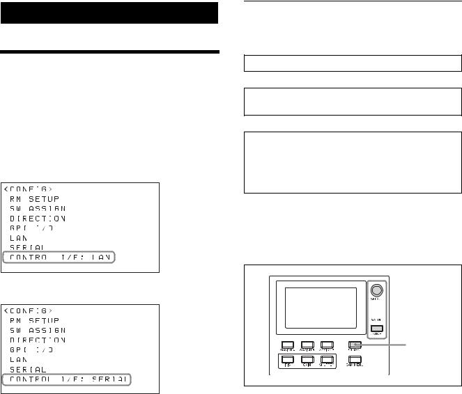
Connections
You can connect the unit to cameras using VISCA over IP (LAN) connection or VISCA RS-422 (serial) connection.
The connection method that is used is displayed at the bottom of the CONFIG menu item in the RM menu.
VISCA over IP (LAN) connection
VISCA over IP (LAN) connection
VISCA over IP (LAN) connection is configured using the following sequence.
Setting the IP address of the unit (page 14)
m
Connecting remote controllers, cameras, and setup PC using LAN connection (page 16)
m
Assigning cameras (page 17)
•Assignment using AUTO IP SETUP >SETUP IP (page 17)
•Assignment using AUTO IP SETUP >ASSIGN CAM (page 18)
Setting the IP address of the unit
Before connection, set the IP address of the unit.
The setting is configured using CONFIG >LAN in the
RM menu.
VISCA RS-422 (serial) connection

 2~11
2~11
1
•For details about VISCA over IP (LAN) connection, see “VISCA over IP (LAN) connection” (page 14).
•For details about VISCA RS-422 (serial) connection, see “VISCA RS-422 (serial) connection” (page 21).
For details about connections, refer to the operating instructions supplied with the camera.
1 Press the RM MENU button, turning it on (button is lit yellow).
The RM menu top menu appears.
2 Turn the SELECT knob to move the cursor to CONFIG.
3 Press the SELECT button. The CONFIG menu appears.
4 Turn the SELECT knob to move the cursor to LAN, and press the SELECT button.
14

The LAN menu appears.
The MAC address is displayed at the bottom.
5 Turn the SELECT knob to move the cursor to IP.
6 Set the IP address using the SELECT knob and VALUE knob/button.
The default setting is 192.168.0.10.
1Turn the SELECT knob clockwise to move the cursor to the first three digits (for example, 192).
IP:p192. 168. 0. 10
2Turn the VALUE knob to set the value. Turning clockwise increases the value, and turning counterclockwise decreases the value.
3Turn the SELECT knob to move to the next number and repeat step 2 to set the other numbers.
7 Set SM (subnet mask) and GW (default gateway address) in the same way as described in steps 5 and
6.
8 When finished making all settings, move the cursor to APPLY.
9 Turn the VALUE knob to change NOT EXEC to EXEC, then press the VALUE button.
The following message appears, prompting you to reboot the unit.
10 Turn the SELECT knob to move the cursor to CONFIRM.
11 Turn the VALUE knob to change NO to YES, then press the VALUE button.
The unit reboots automatically.
Upon rebooting, the IP address setting is completed.
15

Connecting remote controllers, cameras, and setup PC using LAN connection
Connection example
RM-IP500
BRBK-IP10 IP control card*3
BRC-H900
1 |
2 |
3 |
4 |
5 |
6 |
7 |
8 |
9 |
1 |
2 |
3 |
R |
|
|
|
|
|
|
|
|
|
|
|
|
IR SELECT |
|
|
|
|
||
|
VISCA RS-422 |
|
|
OFF |
|
ON |
HD |
SD |
RGB/COMPONENT |
||||||
|
|
|
|
|
|
|
|
|
75 |
|
|
|
|||
IN VISCA |
RS-232 OUT |
EXT SYNC IN |
|
VIDEO |
S VIDEO SDI OUT |
DC IN 12V |
|||||||||
BRBK-IP10 |
|
|
|
|
|
|
|
|
1 |
2 |
DATA MIX |
|
|||
|
|
|
|
|
|
|
|
|
|
|
OFF |
|
|||
|
|
ON |
|
LAN |
SDI OUT |
HD |
SD |
BRC-X1000, |
BRC-H800 |
|
! |
|
|
|
|
|
|
|
|
|
|
|
IR SELECT |
CAMERA SETUP |
|
*1 |
|||
|
Switching hub |
|
1 |
2 |
3 |
|
|
Video switcher |
|
RM-IP10 |
SYSTEM |
IN VISCA RS - 422 |
|
OUT |
OSD |
12V |
|||
|
|
ON OFF |
|
|
|||||
|
|
|
LAN |
|
|
||||
|
|
SELECT |
|
|
|
|
|
|
|
|
|
HDMI OUT |
MONITOR OUT |
LINE OUT |
EXT SYNC IN |
|
|
||
|
|
|
SDI 1 |
|
SDI 2 |
SDI 1 SDI 2 |
|
TERMI- |
|
|
|
|
|
|
|
|
|
NATION |
|
ON OFF |
Setup PC
Video monitor
 SRG-360SHE
RAUD RATE |
MIC |
VISCA RS-422 |
IR SELECT |
R |
L |
|
|
|
(PLUG IN POWER) |
|
|
SYSTEM |
HDMI OUT |
SDI OUT |
LAN |
SELECT |
Remote control signal: LAN cable (category 5 or higher)
Tally/contact signal: Connection cable with D-sub 15-pin connectors*2
Video signal: HDMI cable*2
Video signal: Connection cable with BNC connectors
Signal flow
*1 For an example connection with a video switcher, see “Connection with a video switcher” (page 24).
*2 Use a connection cable designed for the switcher being used. For the specifications of the GPI I/O connector of the unit, see “Pin assignments” (page 52).
*3 To connect the BRC-H900 using a LAN connection, a BRBK-IP10 IP control card must be installed. In addition, use an IP control card with firmware version 2.1 or later.
1 Connect the LAN connector of the units and LAN connector of the cameras using LAN cables.
You can connect up to 100 cameras and five remote controllers on the same network.
2 To configure setting of the unit and cameras using setup software, connect a PC to the same network.
•Use shielded-type LAN cables to prevent malfunction that may result from radiation noise.
•Use a LAN cable (category 5 or higher).
•Connect the cameras, remote controllers, and PC via switching hubs (10BASE-T or 100BASETX). Use on a network with significant packet loss or delay may cause a malfunction. Use a high-quality network.
•Do not mix 10BASE-T and 100BASE-TX in the network.
•The IP address of the unit is set to 192.168.0.10, and the IP address of a camera and BRBK-IP10
16

IP control card is set to 192.168.0.100 by factory default.
•Connecting stackable switching hubs in up to 2- tier configuration is recommended to avoid network delay.
Notes
•Do not connect more than 100 cameras, five remote controllers, and one setup PC across all networks, even if controlling a camera that is on a network of a different segment via a router. If you connect more devices than this, problems may occur, such as control delays or cameras are operated incorrectly due to IP address duplication.
•If you perform the setup from multiple PCs, the settings may not be made correctly. Perform the setup from one PC.
•Set the setup PC so that only the network that you use is enabled.
•Do not connect cameras and remote controllers to a public network.
3 Connect the cameras and remote controllers to AC outlets using AC adapters and AC power cords. The cameras pan/tilt automatically when power is turned on.
Assigning cameras
Link the camera numbers, used for operating cameras from the unit, with the cameras on the network. This is called camera assignment.
A list of the assigned cameras is saved in the unit as a camera table.
Camera numbers are sequential in each group, and are selected using the GROUP buttons and CAMERA number buttons of the camera selection block.
Camera assignments are performed using AUTO IP SETUP >SETUP IP or AUTO IP SETUP >ASSIGN CAM in the RM menu.
Note
Only cameras that are on the same segment as the remote controller can be assigned using AUTO IP SETUP.
Use the setup software to assign cameras on different segments.

 3~
3~
2
1 Check that the assigned camera is connected to the network, and that the camera power is turned on.
2 Press the RM MENU button, turning it on (button is lit yellow).
The RM menu top menu appears.
3 Turn the SELECT knob to move the cursor to AUTO IP SETUP.
4 Press the SELECT button.
The AUTO IP SETUP menu appears.
5 Turn the SELECT knob to select SETUP IP or ASSIGN CAM, and press the SELECT button. Select one of the following methods, depending on the type of camera assignment.
•For connections on a new network: “Assignment using AUTO IP SETUP >SETUP IP” (page 17)
•For adding an assignment to an existing network: “Assignment using AUTO IP SETUP >ASSIGN CAM” (page 18)
Assignment using AUTO IP SETUP >SETUP IP
This method detects cameras on the network, and automatically assigns the IP address setting and camera number for unregistered cameras.
Use this method when constructing a new network. With this method, you specify the range of IP addresses assigned to cameras by entering the start address in [FROM] and the end address in [TO]. Set the range of IP addresses for assignment so that they are in the same segment as the remote controller.
Note
The same IP address as a remote controller cannot be set.
The subnet mask (SM) and gateway address (GW) of the camera are assigned the same settings as the remote controller.
17
 Loading...