


PXW-Z190

4-740-700-11(1)
Solid-State Memory
Camcorder
Operating Instructions
Before operating the unit, please read this manual thoroughly
and retain it for future reference.
PXW-Z190V/PXW-Z190T
© 2018 Sony Corporation

Table of Contents
Overview
Preparation
Location and Function of Parts ............................................... 6
Main unit ........................................................................ 6
Screen Display ......................................................................... 11
LCD/viewfinder screen ................................................ 11
Status screen ................................................................. 13
Power Supply ........................................................................... 16
Using a battery pack ..................................................... 16
Using AC power ........................................................... 17
Turning the camcorder on/off ...................................... 17
Setting the Clock ..................................................................... 18
Attaching Devices .................................................................... 18
Attaching the lens hood ................................................ 18
Attaching the large eyecup ........................................... 18
Adjusting the Screens ............................................................. 19
Adjusting the LCD screen ............................................ 19
Adjusting the viewfinder .............................................. 19
Adjusting the brightness of the LCD/viewfinder
screen using an assignable button .......................... 19
Using Memory Cards .............................................................. 20
About memory cards .................................................... 20
Inserting memory cards ................................................ 20
Removing a memory card ............................................ 20
Switching between memory cards ...............................20
Formatting (initializing) a memory card ...................... 20
Checking the remaining recording time ....................... 21
Restoring a memory card ............................................. 21
Shooting
Basic Operation Procedure .................................................... 22
Shooting ....................................................................... 22
Adjusting the zoom ...................................................... 23
Adjusting the focus ...................................................... 24
Monitoring audio while shooting ................................. 25
2

Changing Basic Settings ......................................................... 25
Video format ................................................................ 25
Adjusting the brightness ............................................... 26
Adjusting for natural colors (white balance) ................ 27
Setting the audio to record ........................................... 29
Image stabilization ....................................................... 31
Time data ...................................................................... 31
Useful Functions ...................................................................... 32
Direct menu operation .................................................. 32
Face detection AF ........................................................ 33
Color bars/reference audio tone ................................... 34
Reviewing a recording (Rec Review) .......................... 34
Assignable buttons ....................................................... 34
Interval recording (Interval Rec) .................................. 35
Continuous recording (Clip Continuous Rec) .............. 36
Picture cache recording (Picture Cache Rec) ............... 37
Slow & Quick Motion .................................................. 37
Simultaneous recording in 2 slots (Simul Rec) ............ 38
High dynamic range (HDR) recording ......................... 39
Saving and loading configuration data ......................... 39
Acquiring location information (GPS) ......................... 42
Proxy Recording ..................................................................... 43
Supported SD cards ...................................................... 43
Formatting (initializing) SD cards ............................... 43
Checking the remaining capacity ................................. 43
Proxy recording (Proxy Rec) ....................................... 43
Changing proxy recording settings .............................. 44
About the recorded file ................................................. 44
Storage destination of the recorded file ....................... 44
About the file name ...................................................... 44
Recording proxy data only ........................................... 44
Connecting to Other Devices via LAN .................................. 45
Connecting using wireless LAN access point mode .... 45
Connecting using wireless LAN station mode ............. 46
List of functions for network connections ................... 49
Using Web Remote Control ................................................... 50
Thumbnail Screen
Configuration of the Thumbnail Screen ............................... 52
Playing Clips ............................................................................ 53
Playing recorded clips .................................................. 53
Playing the selected and subsequent clips in
sequence ................................................................. 53
Monitoring audio during playback ............................... 53
3

Clip Operations ....................................................................... 54
External Device Connection
Connecting External Monitors and Recording Devices ...... 58
Managing/Editing Clips on a Computer ............................... 59
Menu Display and Settings
Setup Menu Configuration and Hierarchy .......................... 62
Setup Menu Operations .......................................................... 64
Setup Menu List ...................................................................... 68
Thumbnail menu operations ......................................... 54
Displaying clip properties ............................................ 55
Protecting clips ............................................................. 56
Copying clips ............................................................... 56
Deleting clips ............................................................... 57
Filtering clips (frames) using the essence mark
thumbnail screen .................................................... 57
Changing the information displayed on the thumbnail
screen ..................................................................... 57
Connecting using a USB cable ..................................... 59
Connecting an external HDD/USB media ................... 59
Setup menu hierarchy ................................................... 62
Editing the User menu .................................................. 66
User menu .................................................................... 68
Edit User Menu menu .................................................. 68
Camera menu ............................................................... 69
Paint menu .................................................................... 72
Audio menu .................................................................. 77
Video menu .................................................................. 79
LCD/VF menu .............................................................. 79
TC/UB menu ................................................................ 83
Recording menu ........................................................... 83
Thumbnail menu .......................................................... 85
Media menu .................................................................. 86
File menu ...................................................................... 87
Network menu .............................................................. 88
System menu ................................................................ 90
Appendix
Important Notes on Operation .............................................. 94
Using your camcorder abroad ...................................... 94
4

Video Formats ....................................................................... 100
About recording media ............................................... 100
Special recording modes and compatible formats ..... 100
Maximum recording time for a clip ........................... 101
Output Formats and Limitations ........................................102
Video formats and output signals ............................... 102
Limitations between recording functions ................... 104
Troubleshooting .................................................................... 105
Power supply .............................................................. 105
Recording/playback .................................................... 105
External devices ......................................................... 106
Wireless LAN connection .......................................... 106
Error/Warning Indications .................................................. 107
Error indications ......................................................... 107
Warning indications ................................................... 107
Caution and operation messages ................................ 108
Block Diagrams ..................................................................... 110
Specifications ......................................................................... 113
General ....................................................................... 113
Lens ............................................................................ 114
Camera ....................................................................... 114
Wireless LAN ............................................................. 115
Inputs/outputs ............................................................. 115
Display ....................................................................... 115
Internal microphone ................................................... 115
Media slots ................................................................. 115
Supplied accessories ...................................................115
Index ....................................................................................... 118
5
Overview
Location and Function of Parts
For details about the usage and function of each part, see the referenced page.
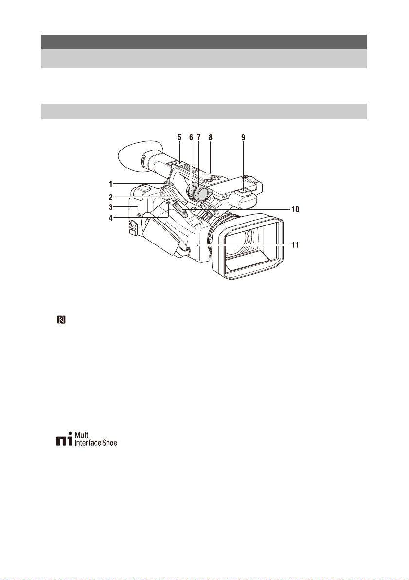
Main unit
1. Hook for shoulder strap (9)
2. ASSIGN7/DIRECT MENU button (34)
3. (N mark)
• Hold an NFC-compatible smartphone near
this mark to establish a wireless connection
between the camcorder and smartphone.
For details, refer to the operating
instructions of the smartphone.
• NFC (Near Field Communication) is an
international standard for short-range radio
communication.
4. ASSIGN8/FOCUS MAG button
5. Multi Interface Shoe (rear)
For details about accessories supported by the
Multi Interface Shoe, contact your sales
representative.
6. Microphone clamper
7. Microphone holder (30)
8. GPS antenna
9. Multi Interface Shoe (front)
10. Power zoom lever (23)
11. Wi-Fi antenna
6
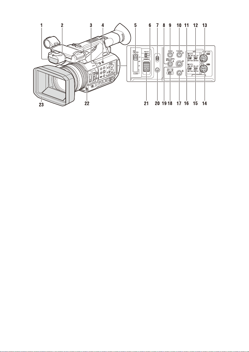
1. Internal microphone (29)
2. Recording/tally lamp (front) (92)
Flashes when the remaining capacity on the
recording media or battery is low.
3. ASSIGN6 button
4. FULL AUTO button (22)
5. ND FILTER switch
6. ND FILTER mode switch
7. FOCUS switch (24)
8. ASSIGN3/VIDEO SIGNAL MONITOR
button
9. ASSIGN1/ZEBRA button
10. ASSIGN2/PEAKING button
11. INPUT1 switch (29)
12. CH1 (INT/EXT/MI SHOE) switch (29)
13. AUDIO LEVEL (CH1) dial (29)
14. AUDIO LEVEL (CH2) dial (29)
15. CH2 (INT/EXT/MI SHOE) switch
16. INPUT2 switch (29)
17. ASSIGN5 button
18. SHUTTER switch
19. ASSIGN4 button
20. FOCUS PUSH AUTO/HOLD button (24)
21. ND control dial
22. WB SET button
23. Lens hood with lens cover (18)
7
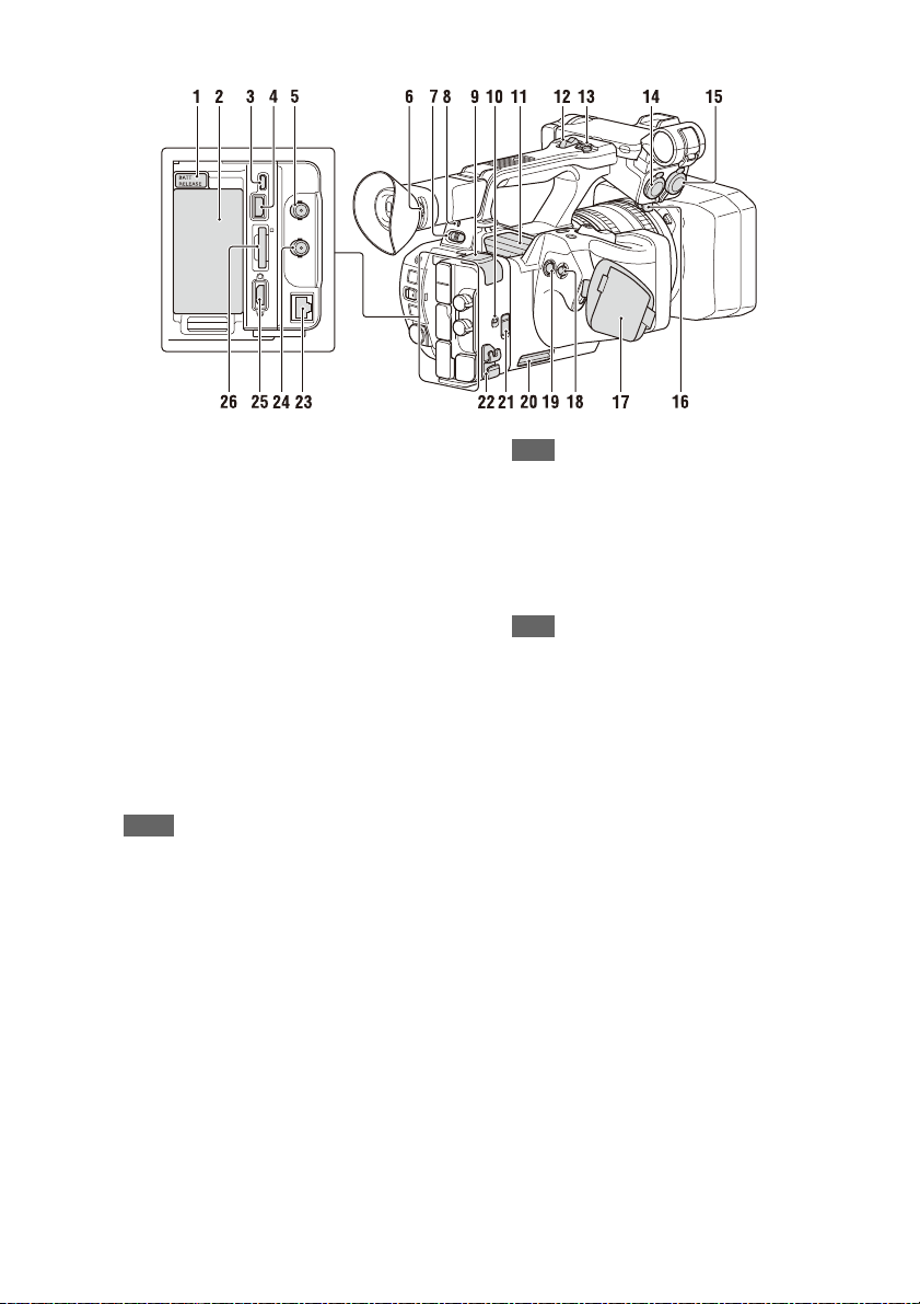
1. BATT RELEASE button (16)
2. Battery pack attachment (16)
3. Multi/Micro USB connector (59)
4. USB3.0 (HOST) connector (type A)
5. SDI OUT connector (58)
6. Diopter adjustment dial (19)
7. ON/STANDBY switch (17)
?: ON
1: STANDBY
8. Power lamp
9. USB2.0 (HOST) connector (type A)
(Supported in a future upgrade.)
10. IN/OUT (input/output selector) switch
11. Air outlet
Notes
• Areas around the air outlet may become hot.
• Do not cover the air outlet.
12. Handle zoom lever (23)
13. Handle record button
When the lever is set to the HOLD position, the
handle record button is not operable.
14. AUDIO INPUT1 connector (29)
15. AUDIO INPUT2 connector (29)
16. Cable holder
Provided for securing a microphone cable, etc.
17. Grip belt
18. Multi selector (V/v/B/b/SET button)
19. Record button (22)
20. Air inlet
Note
• Do not cover the air inlet.
21. REMOTE connector
The REMOTE connector is used for controlling
start/stop of recording and other functions on the
video device and peripherals connected to it.
22. Cable clamper
Note
• Do not use for any purpose other than securing
cables.
23. Wired LAN connector (supported in
future upgrade)
24. TC IN/OUT connector
25. HDMI OUT connector (58)
26. UTILITY SD/MS slot/access lamp
Used for proxy recording and storing/loading
settings (File function). To be supported by a
future upgrade (software update).
8
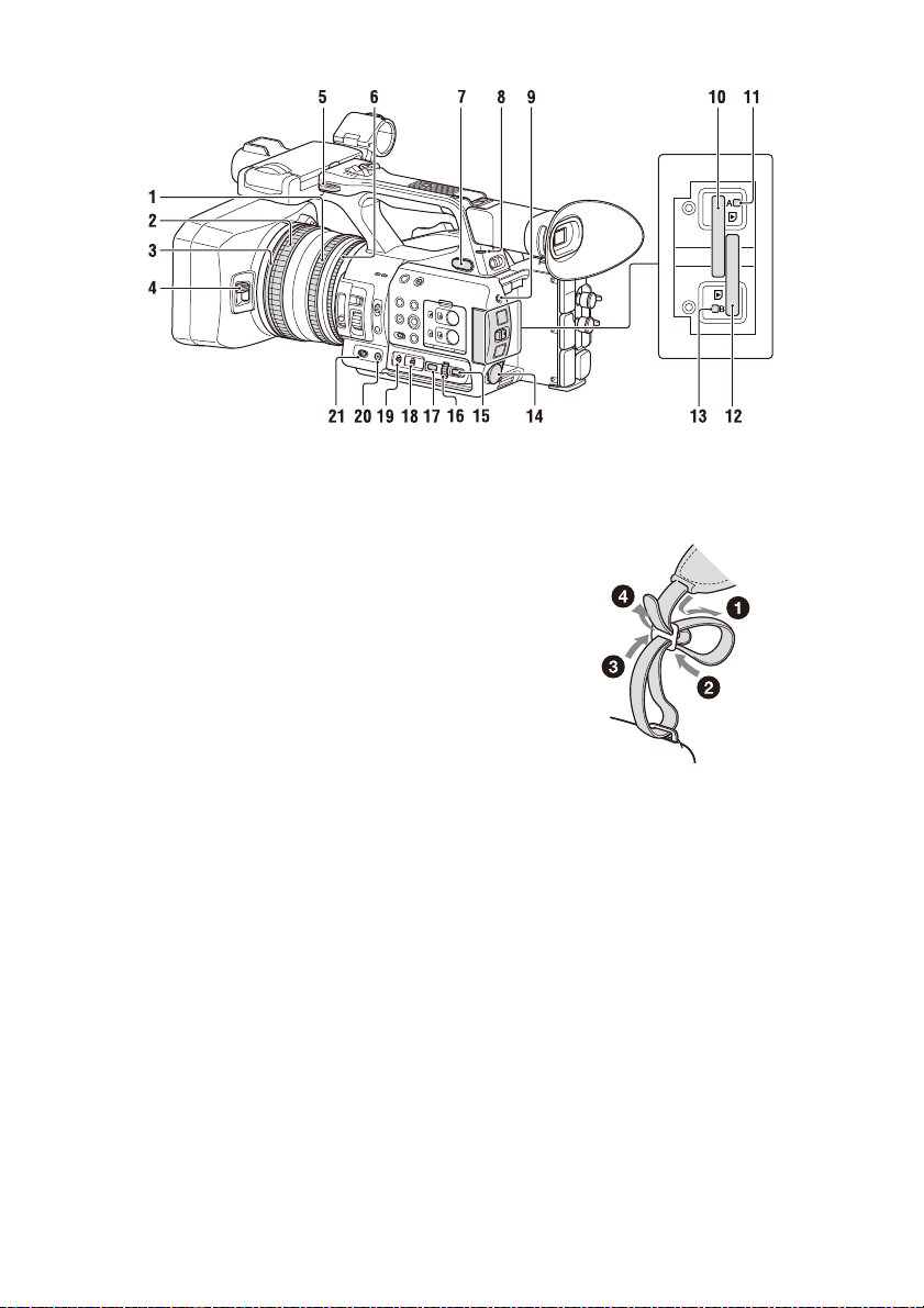
1. Zoom ring (24)
2. Focus ring (24)
3. Full MF switch (24)
Switch manual focus mode on/off by moving
the focus ring forward/back.
4. Lens cover lever (18)
Opens/closes the lens cover.
5. Hook for shoulder strap
6. Iris ring (26)
7. i (headphone) jack
For stereo mini-jack headphones.
8. Recording/tally lamp (rear) (92)
Flashes when the remaining capacity on the
recording media or battery is low.
9. SLOT SELECT button
10. Memory card slot A
11. Memory card A access lamp (20)
12. Memory card slot B
13. Memory card B access lamp (20)
14. DC IN connector
15. CANCEL/BACK button (64)
16. SEL/SET dial (64)
17. MENU button (64)
Button has a raised tactile bar for your
convenience in locating the button.
18. WHT BAL switch (28)
19. GAIN switch (26)
20. IRIS PUSH AUTO button
21. IRIS switch (26)
To attach a shoulder strap
Attach a shoulder strap to the hooks for the
shoulder strap.
9
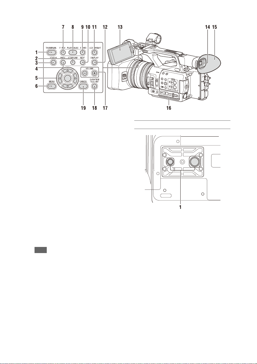
1. THUMBNAIL button (52)
2. STOP/CAM button (53)
3. STATUS CHECK button (13)
4. PREV button (53)
5. V/v/B/b/SET button (64)
6. MENU button (64)
7. F REV button (53)
8. PLAY/PAUSE button (53)
9. F FWD button (53)
10. NEXT button (53)
11. LCD BRIGHT button (19)
12. DISPLAY button (11)
13. LCD screen (19)
14. Viewfinder (19)
15. Large eyecup
16. Air inlet
Note
• Do not cover the air inlet.
17. VOLUME buttons (25)
18. DURATION/TC/U-BIT button (31)
19. CANCEL button (64)
Bottom Side
1. Tripod screw holes (1/4 inch, 3/8 inch)
Compatible with 1/4-20UNC screws and 3/816UNC screws.
Attach to a tripod (sold separately, screw length
of 5.5 mm or less).
10
Screen Display
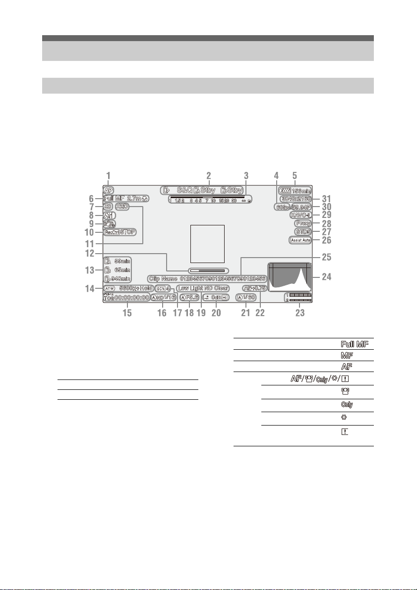
Information displayed on the screen while shooting
LCD/viewfinder screen
While recording, standing by to record, or during playback, the statuses and settings of the camcorder are
superimposed on the LCD/viewfinder screen.
You can show/hide the information using the DISPLAY button.
You can also select to show/hide each item independently (page 81).
1. Network status indicator (page 12)
Displays the status of the network connection as
an icon.
2. Recording mode/slot A/B operation status
indicator
zRec Recording
Stby Recording standby
3. Depth-of-field indicator
4. Slow & Quick Motion shooting frame rate
indicator
5. Remaining battery capacity/DC IN
voltage indicator
6. Focus mode indicator (page 33)
Full MF mode
MF mode
AF mode
Face detection AF ( )
Face detection icon
Face only AF icon
Registered face icon
Face Only AF mode auto
focus paused icon
a) Displayed when there is no registered face and
no faces are detected, and when there is a
registered face but it is not detected.
a)
7. Zoom position indicator
Displays zoom position in the range of 0 (wide
angle) to 99 (telephoto).
8. GPS status indicator
9. Image stabilization mode (SteadyShot)
indicator
11
10. SDI output/HDMI output Rec Control
indicator
Displayed when Display On/Off >SDI/HDMI
Rec Control in the LCD/VF menu and SDI/
HDMI Rec Control >Setting in the Video menu
are both set to On.
11. Digital extender indicator (page 91)
12. Focus assist indicator
13. Media remaining capacity indicator
14. White balance mode indicator
ATW Automatic mode
ATW Hold Pause automatic mode
W:P Preset mode
W:A Memory A mode
W:B Memory B mode
15. Timecode indicator (page 31)
16. ND filter indicator (page 27)
17. Scene file indicator (page 39)
18. Iris position indicator
19. Video level warning indicator
20. Gain indicator (page 26)
21. Shutter mode/shutter speed indicator
22. AE mode/AE level indicator (page 27)
23. Audio level meter
24. VIDEO SIGNAL MONITOR display
(waveform monitor/vectorscope/
histogram)
25. Clip name indicator
26. Gamma display assist indicator (page 39)
27. Gamma indicator (page 74)
Displays the gamma setting.
28. Proxy status indicator
29. Recording format (codec) indicator
(page 90)
Displays the format that is recorded on a
memory card.
30. System frequency and scan method
indicator
31. Recording format (picture size) indicator
(page 90)
Displays the picture size that is recorded on a
memory card.
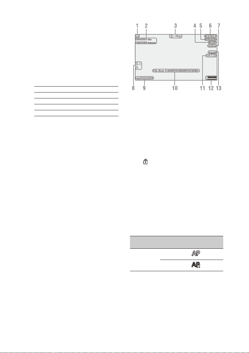
Information displayed on the playback screen
The following information is superimposed on
the playback picture.
1. Network status indicator
2. Clip number/Total number of clips
3. Playback mode indicator
4. Playback format (frame rate) indicator
5. Playback format (picture size) indicator
6. Remaining battery capacity/DC IN
voltage indicator
7. Playback format (codec) indicator
8. Media indicator
A mark appears to the left if the memory
card is write-protected.
9. Time data indicator
The time data is disp layed when Display On/Off
>Timecode in the LCD/VF menu is set to On
and the DISPLAY button is pressed.
10. Clip name indicator
11. Gamma display assist indicator
12. Audio level meter
13. Gamma indicator
Network connection icon indicators
Network
mode
Access point
mode
Connection
status
Operating as an
access point
Access point
operation error
Icon
12
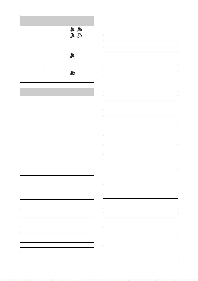
Network
mode
Station mode Wi-Fi
Connection
status
connected
Wi-Fi signal
strength (4
levels)
Wi-Fi
disconnected
(incl. during
setup)
Wi-Fi
connection
error
Icon
Status screen
You can check the settings and status of the
camcorder on the status screen.
Status screen operations
To display the status screen:
• Push the STATUS CHECK button.
To switch the status screen:
• Turn the SEL/SET dial or press the V/v button.
To hide the status screen:
• Push the STATUS CHECK button.
Camera Status screen
Displays the picture quality, zoom settings, and
status.
White Switch<B> White balance memory B
White Switch<A> White balance memory A
White Switch<P> Preset White setting
ND<Preset> Preset1 to 3 setting for ND
Zebra1 Zebra1 On/Off setting and
Zebra2 Zebra2 On/Off setting and
Gamma Gamma category and curve
Gain Switch Gain<L>, Gain<M>,
Handle Zoom Speed Handle Zoom setting
Scene File Current scene file and file ID
adjustment value
adjustment value
Filter
level
level
Gain<H> setting
Audio Status screen
Displays the input setting, audio level meter, and
wind noise reduction filter setting for each
channel.
CH1 level meter CH1 level meter
CH1 Input Source CH1 input source
CH1 Ref./Sens. CH1 input reference level
CH1 Wind Filter CH1 microphone wind
reduction filter setting
CH2 level meter CH2 level meter
CH2 Input Source CH2 input source
CH2 Ref./Sens. CH2 input reference level
CH2 Wind Filter CH2 microphone wind
reduction filter setting
CH3 level meter CH3 level meter
CH3 Input Source CH3 input source
CH3 Ref./Sens. CH3 input reference level
CH3 Wind Filter CH3 microphone wind
reduction filter setting
CH4 level meter CH4 level meter
CH4 Input Source CH4 input source
CH4 Ref./Sens. CH4 input reference level
CH4 Wind Filter CH4 microphone wind
reduction filter setting
HDMI Output CH HDMI output audio channel
combination setting
Analog Output CH Analog output audio channel
combination setting
Monitor CH Monitor channel setting
Headphone Out Headphone output type
setting
System Status screen
Displays the video signal settings.
Frequency/Scan System frequency and
scanning method settings
Codec Codec setting
Simul Rec 2-slot Simul Rec On/Off
status
Title Prefix Clip name title prefix
Picture Size Recording format picture size
Rec Function Enabled special recording
format and settings
Clip Continuous Rec Clip Continuous Rec On/Off
status
Picture Cache Rec Picture Cache Rec On/Off
status and setting
Number Clip name numeric suffix
Shooting Mode Shooting mode setting
13

Proxy Rec Proxy recording On/Off
status and setting
Video Output Status screen
Displays the SDI, HDMI, and video output
settings.
SDI Output picture size
Rec Control status
Output On/Off
HDMI Output picture size
Rec Control status
Output On/Off
Gamma Gamma setting
Color Gamut Color gamut setting
Gamma Display Assist Gamma display assist setting
Assignable Button Status screen
Displays the functions assigned to each of the
assignable buttons.
1 Function assigned to the
Assign 1 button
2 Function assigned to the
Assign 2 button
3 Function assigned to the
Assign 3 button
4 Function assigned to the
Assign 4 button
5 Function assigned to the
Assign 5 button
6 Function assigned to the
Assign 6 button
7 Function assigned to the
Assign 7 button
8 Function assigned to the
Assign 8 button
Battery Status screen
Displays information about the battery and DC IN
source.
Detected Battery Battery type
Remaining Remaining capacity (%)
Charge Count Number of recharges
Capacity Remaining capacity (Ah)
Voltage Voltage (V)
Manufacture Date Date of battery manufacture
Video Lig ht Remaining Remaining charge level of t he
video light battery
Power Source Power supply source
Supplied Voltage Supplied power source
voltage
Media Status screen
Displays the remaining space, available recording
time, and estimated service life of the recording
media (memory card A/memory card B) and
UTILITY media.
Media A information Displays the media icon
Media A protection Displays the lock icon when
Media A remaining
capacity meter
Media A remaining
recording time
Media B information Displays the media icon
Media B protection Displays the lock icon when
Media B remaining
capacity meter
Media B remaining
recording time
UTILITY media
information
UTILITY media
protection
UTILITY media
remaining capacity
meter
when recording media is
inserted in slot A.
the recording media inserted
in slot A is protected
(locked).
Displays the remaining
capacity of recording media
inserted in slot A expressed
as a percentage on a bar
graph.
Displays an estimate of the
remaining recording time of
the recording media inserted
in slot A in units of minutes
under the current recording
conditions.
when recording media is
inserted in slot B.
the recording media inserted
in slot B is protected
(locked).
Displays the remaining
capacity of recording media
inserted in slot B expressed
as a percentage on a bar
graph.
Displays an estimate of the
remaining recording time of
the recording media inserted
in slot B in units of minutes
under the current recording
conditions.
Displays the media icon
when media is inserted in the
UTILITY SD/MS slot.
Displays the lock icon when
the media inserted in the
UTILITY SD/MS slot is
protected (locked).
Displays the remaining
capacity of media inserted in
the UTILITY SD/MS slot
expressed as a percentage on
a bar graph.
14

UTILITY media
remaining capacity
Displays an estimate of the
remaining recording time of
the recording media inserted
in the UTILITY SD/MS slot
in units of minutes. Or
displays the remaining
capacity in units of GB.
Rec Button Settings Status screen
Displays the setting status of the record button
and handle record button.
Rec Button Displays the recording target
Handle Rec Button Displays the recording target
slot of the record button
slot of the handle record
button
GPS Status screen
Displays the GPS positioning status and
information.
GPS GPS signal positioning status
Dilution of Precision Position information
Latitude Latitude information
Longitude Longitude information
Altitude Altitude information
Positioning date and
time
Current date and time Current date and time
Time Zone Time zone setting
precision
Positioning date and time
Setting
display
Station Mode Non Active Not operating in
Status
Description
display
station mode.
Displayed when
Wi-Fi chip fails.
Searching Attempting to
Disconnected Not connected to a
<SSID> Connected to
connect to the
previously
connected network
(access point).
network (access
point).
Also displayed
when IP address
was not assigned
using DHCP.
<SSID> network
(access point).
Network Status screen
Displays the connection status of the network
connection.
Wireless LAN Wireless network settings,
connection status
Wireless LAN settings
Setting
display
Off --- Wireless LAN
Access Point
Mode
Status
Description
display
setting is off.
Non Active Not operating as an
Active Operating as an
access point.
Displayed when
Wi-Fi chip fails.
access point.
15
Preparation
Power Supply
You can use a battery pack or AC power supply
from an AC adapter.
When an AC adapter is connected, the AC
adapter has priority even when a battery pack is
attached.
For safety, use only the Sony battery packs and
AC adaptors listed below.
Lithium-ion battery packs
BP-U30 (supplied)
BP-U60
BP-U60T
BP-U90
AC adapters/chargers
BC-U1A (supplied)
BC-U2A
WARNING
Do not store battery packs in locations exposed to
direct sunlight, flame, or high temperature.
Note
• When operating from a power outlet, use the supplied
AC adapter.
Using a battery pack
To attach a battery pack, plug the battery pack
into the attachment (page 8) as far as it will go,
and then slide it down to lock it into position.
To remove a battery pack, press and hold the
BATT RELEASE button (page 8), slide the
battery pack up and then pull it out of the
attachment.
Notes
• Before use, charge the battery pack with the BC-U1A
(supplied) or BC-U2A Charger.
• Charging a battery immediately after use while it is
still warm may not fully recharge the battery.
• The high-capacity BP-U90 Battery Pack is large, and
protrudes from the camcorder when attached. The BPU90 is convenient when using the camcorder attached
to a tripod for extended recording periods.
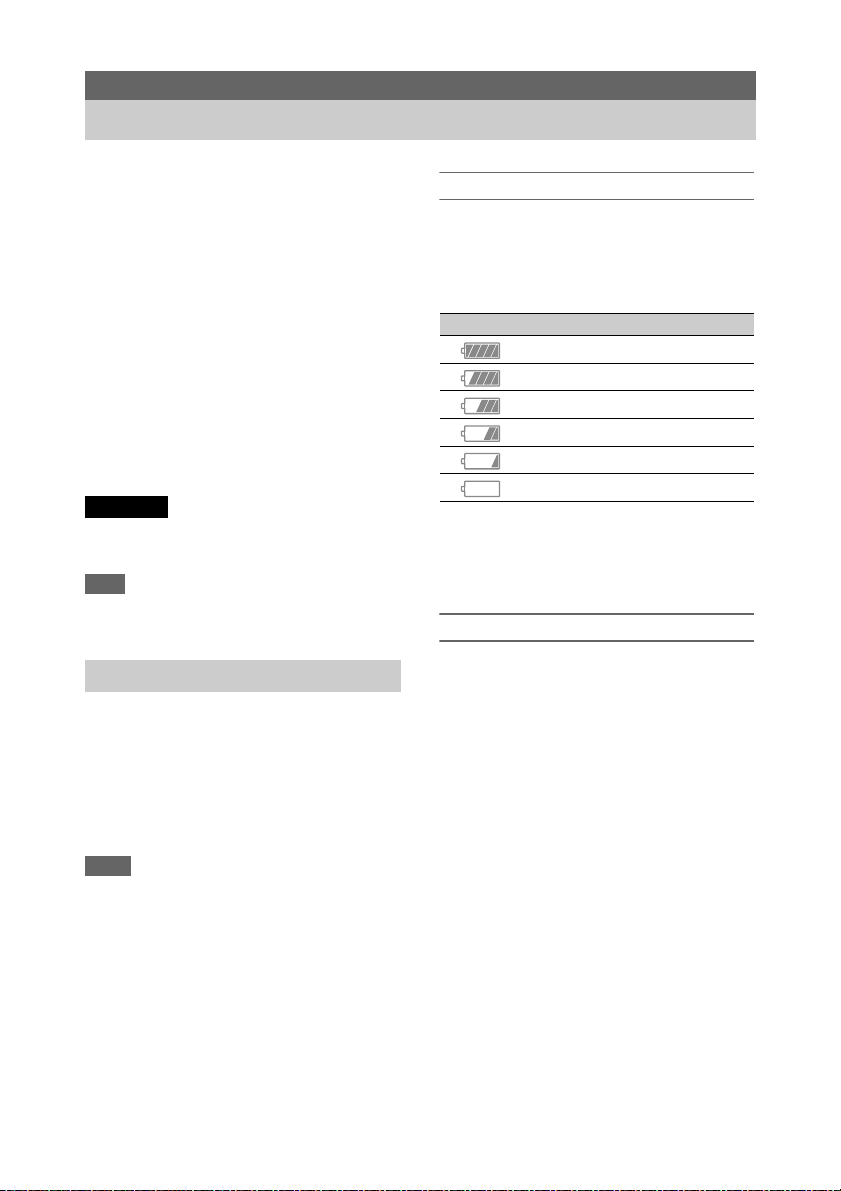
Checking the remaining capacity
When recording or playback is in progress on the
battery pack, an icon to show the current battery
charge level and usage time remaining are
displayed on the LCD/viewfinder screen
(page 11).
Icon Remaining capacity
100% to 91%
90% to 71%
70% to 51%
50% to 31%
30% to 11%
10% to 0%
The camcorder indicates the remaining usage
time in minutes by calculating the available time
with the battery pack if operation is continued at
the current rate of power consumption.
If the battery pack charge becomes low
If the remaining battery charge falls below a
certain level during operation (Low Battery
state), a low-battery message appears, the
recording/tally lamp starts flashing, and a beep
sound will warn you.
If the remaining battery charge falls below the
level at which operation cannot continue (Battery
Empty state), a battery-empty message appears.
Replace with a charged battery pack.
Changing the warning levels
The Low Battery level is set to 10% of full battery
charge and the Battery Empty level is set to 3% by
factory default. You can change the warning level
settings using Battery Alarm (page 92) in the
System menu.
16
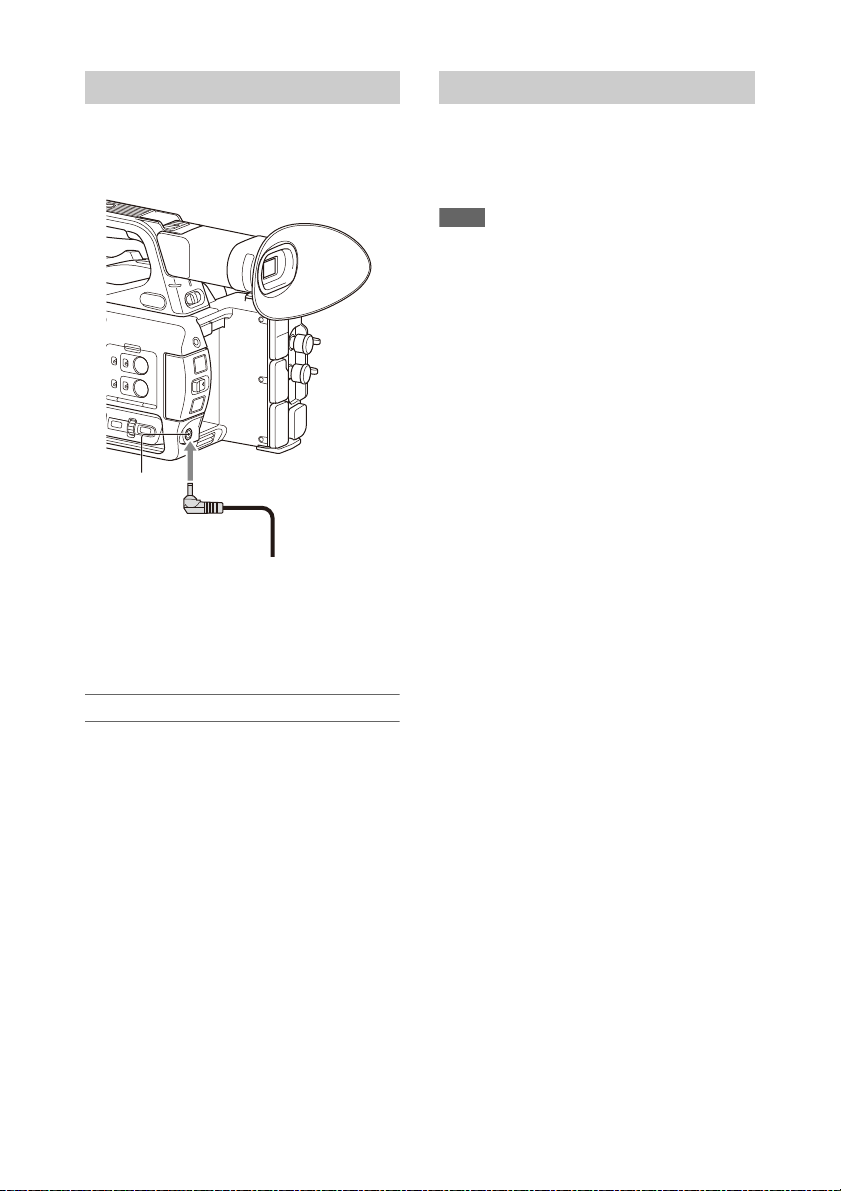
Using AC power
DC IN
connector
AC adapter plug
Turning the camcorder on/off
Connecting the camcorder to a power outlet
allows use without worrying about the need to
recharge the battery pack.
1 Connect the power cord (mains lead) to the AC
Adapter.
2 Connect the A C Adapter to the DC IN connector of the
camcorder.
3 Connect the power cord (mains lead) to the wall outlet
(wall socket).
To turn the camcorder on, set the ON/STANDBY
switch (page 8) to the ON position ([). To turn the
camcorder off, set the ON/STANDBY switch to
the STANDBY position (1).
Notes
• Even when the ON/STANDBY switch is set to the
STANDBY position, the unit continues to draw
standby electric power. Remove the battery pack if not
using your camcorder for an extended period.
• Remove the battery or disconnect the DC IN power
supply after the power lamp is extinguished when the
power switch is set to the STANDBY position. If
power is removed while the switch is in the ON
position, a malfunction of the camcorder or memory
cards may occur.
AC adapters
• Do not connect and use an AC adapter in a
confined space, such as between a wall and
furniture.
• If a problem occurs during operation,
immediately disconnect the power cord from
the outlet.
• Do not short-circuit the plug of the AC adapter
with any metallic objects. Doing so will cause a
malfunction.
• You cannot charge the camcorder by
connecting it to the AC Adapter.
17

Setting the Clock Attaching Devices
PUSH (lens hood release) button
Large eyecup (supplied)
When you turn the camcorder on for the first time
after purchasing or the backup battery has
completely discharged, the initial setting display
appears on the viewfinder screen and LCD
screen.
Set the date and time of the internal clock using
this screen.
Time Zone
The value shows the time difference from UTC
(Coordinated Universal Time). Change the
setting as required.
Setting the date and time
Move the cursor using the V/v/B/b button
(page 8) or SEL/SET dial (page 9), and press the
SET button or SEL/SET dial to set each item.
Finally, move the cursor to [Finish] and press the
SET button or SEL/SET dial to close the settings
screen and finish setting the clock.
Once the settings screen is closed, you can change
the date, time, and time zone settings using Clock
Set (page 92) in the System menu.
Notes
• If the clock setting is lost because the backup battery
becomes fully discharged due to power being
disconnected for an extended period (no battery pack
and no DC IN power source), the initial settings screen
will be displayed when you next turn the camcorder
on.
• While the initial settings screen is displayed, no other
operation, except turning the power off, is permitted
until you finish the settings on this screen.
• If you do not use your camcorder for about 3 months,
the built-in rechargeable battery gets discharged and
the date and time settings may be cleared from the
memory. In that case, charge the rechargeable battery
and then set the date and time again (page 96).
Attaching the lens hood
Align the marks on the lens hood to those on
the camcorder, and turn the lens hood in the
direction of the arrow 2 until it is locked.
Removing the lens hood
Turn the lens hood in the opposite direction of the
arrow in the illustration while pressing the PUSH
(lens hood release) button.
Note
• Remove the lens hood when you attach/detach an ø82
mm polarizing filter or protective filter.
Attaching the large eyecup
Stretch the large eyecup slightly and fit it over the
groove on the viewfinder.
18
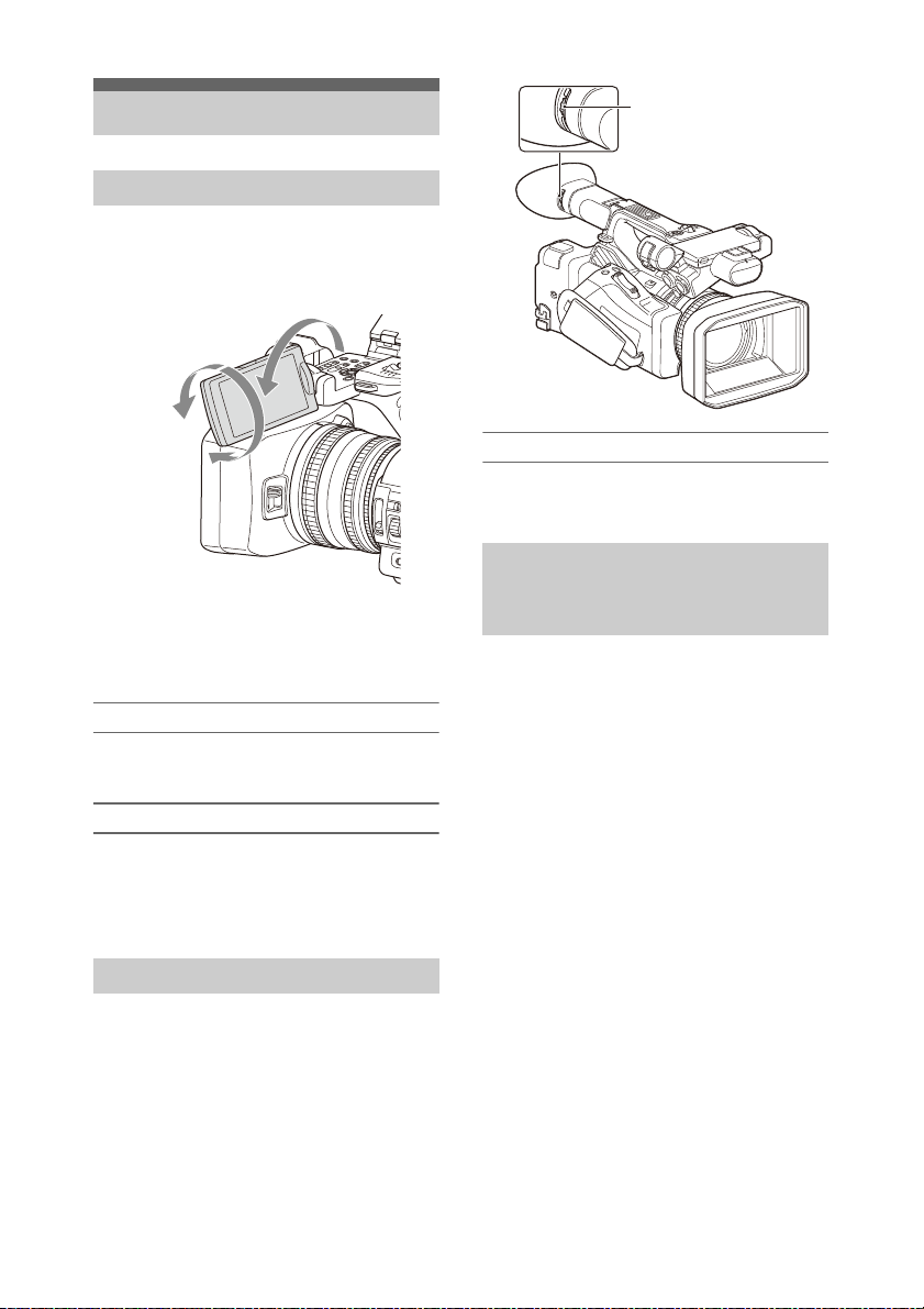
Adjusting the Screens
2 180
degrees
(max.)
2 90
degrees
(max.)
1 Open 180
degrees
Diopter adjustment dial
Move it until the picture
becomes clear.
Adjusting the LCD screen
Open the LCD screen 180 degrees (1), then
rotate it to the best angle to record or play back
(2).
You can adjust the angle so that the viewfinder is
facing the subject. Images are displayed as mirror
images on the LCD screen, but are recorded as
normal images.
Adjusting the backlight
Switch the brightness of the backlight using the
LCD BRIGHT button (page 10).
Adjusting the brightness
Adjust the brightness using LCD Setting
>Brightness (page 79) in the LCD/VF menu.
Changes in the brightness do not affect the
brightness of recorded images.
Adjusting the brightness
Adjust the brightness using VF Setting
>Brightness (page 79) in the LCD/VF menu.
Adjusting the brightness of the
LCD/viewfinder screen using an
assignable button
You can display a level bar for adjusting the
brightness of the LCD screen/viewfinder screen
by assigning LCD/VF Adjust to an assignable
button (page 34) beforehand and then pressing
that button.
1 Press the button assigned with LCD/VF
Adjust to display a level bar for
adjusting the brightness.
Each time the button is pressed, the display
switches in sequence between level bar for
the LCD screen t level bar for the
viewfinder t no display.
Adjusting the viewfinder
Look through the viewfinder with the LCD screen
closed when using the viewfinder.
If the viewfinder screen display is not clear,
adjust it using the diopter adjustment dial below
the viewfinder.
2 Adjust the level using the V/v/B/b
button or SEL/SET dial, and press the
SET button or SEL/SET dial.
The level bar disappears.
Press the button assigned with LCD/VF
Adjust or do not perform any operation for 3
seconds to hide the level bar.
19

Using Memory Cards
• A memory card removed from the camcorder after
recording ended may be hot. This is not a malfunction.
This camcorder records audio and video on
memory cards (sold separately) inserted in the
memory card slots.
About memory cards
Supported memory cards
The following memory cards are supported.
For details about recording media and compatible
formats, see page 100.
SDXC memory cards (Class 10)
Inserting memory cards
1 Open the cover of the card slot block.
2 Insert the memory card with the label
facing to the right.
The access lamp (page 9) lights in red, then
changes to green once the memory card is
ready for use.
3 Close the cover.
Note
• The memory card, memory card slot, and image data
on the memory card may be damaged if the card is
forced into the slot in the incorrect orientation.
Removing a memory card
1 Open the cover of the card slot block,
and lightly press the memory card in.
The memory card pops out.
During recording, this will stop the
recording.
2 Remove the memory card.
Notes
• If the camcorder is turned off or the memory card is
removed while the memory card is being accessed, the
integrity of data on the card cannot be guaranteed. All
data recorded on the card may be discarded. Always
make sure the access indicator is green or off before
turning off the camcorder or removing the memory
card.
Switching between memory cards
When memory cards are loaded in both card slots
A and B, you can switch the card used for
recording by pressing the SLOT SELECT button
(page 9).
If a card becomes full during recording, the
camcorder automatically switches to the other
card.
Note
• The SLOT SELECT button is disabled during
playback. The memory cards are not switched even if
you press the button. The button is enabled while the
thumbnail screen (page 52) is displayed.
Formatting (initializing) a memory
card
Memory cards must be formatted the first time
they are used in the camcorder.
Memory cards for use in the camcorder should be
formatted using the format function of the
camcorder.
If a message appears when the memory card is
inserted into the camcorder, format the memory
card.
If a memory card that was formatted in a format
unsupported by this camcorder is inserted, the
message “Unsupported File System” is displayed
on the LCD/viewfinder screen.
Format the media as described below.
To execute formatting
Using Format Media (page 86) in the Media
menu, specify Media(A) (slot A) or
Media(B) (slot B), then select Execute.
A message is displayed while formatting is in
progress, and the access indicator is lit red.
When formatting ends, a completion message
appears.
Note
• Formatting a memory card erases all data on the card,
including protected video. The data cannot be restored.
To use media formatted on the camcorder in the
slot of another device
Make a backup of the media, then format it using
the other device.
20

Checking the remaining recording
time
While recording (or standing by to record), you
can check the remaining space for the memory
cards loaded in the card slots on the A/B slot
media status/remaining space display of the LCD/
viewfinder screen (page 11).
The remaining recording time is calculated from
the remaining capacity of the media in each slot
and the current video format (recording bit rate),
and is displayed in units of minutes.
Note
• A icon appears if the memory card is writeprotected.
Replacing a memory card
• If the available time on two cards in total
becomes less than 5 minutes, the warning
message “Media Near Full” is displayed, the
recording/tally lamp flashes, and a beep sound
is output to the headphones to warn you.
Replace with media that has free space.
• If you continue recording until the total
remaining time reaches zero, the message
changes to “Media Full,” and recording stops.
Note
• Up to approximately 600 clips can be recorded on one
memory card.
If the number of recorded clips reaches the limit, an
indication that the maximum number of clips has been
reached is displayed.
Restoring a memory card
A message and progress status (%) are displayed
while formatting is in progress, and the access
lamp is lit red.
When restoration ends, a completion message
appears.
If restoration fails
• Write protected memory cards and cards on
which memory errors have occurred cannot be
restored. A warning message appears for such
cards. Follow the instructions in the message
and unprotect the card or replace it with another
card.
• Memory cards on which memory errors have
occurred may become usable if they are
reformatted.
• In some cases, some clips can be restored while
others cannot. The restored clips can be played
normally.
• If the message “Could not Restore Some Clips”
keeps appearing after repeated attempts at
restoration, it may be possible to restore the
memory card with the following procedure.
1 Use the copy function (page 56) of the camcorder to
copy the required clips to another memory card.
2 Format the unusable memory card on the
camcorder.
3 Copy the required clips back to the newly formatted
memory card.
Notes
• For restoration of media recorded with this camcorder,
be sure to use this camcorder.
Media recorded with a device other than this
camcorder or with another camcorder of different
version (even of the same model) may not be restored
using this camcorder.
• Clips with duration of less than 1 minute may not be
restorable.
If for any reason an error should occur in a
memory card, the card must be restored before
use.
When you load a memory card that needs to be
restored, a message appears on the LCD/
viewfinder screen to ask whether you want to
restore it.
Restoring a card
Select Execute using the V/v/B/b button or
SEL/SET dial, and press the SET button or
SEL/SET dial.
21

Shooting
Basic Operation Procedure
Shooting
Basic shooting is conducted using the following
procedure.
1 Attach the necessary devices, and check
that power is being supplied.
2 Load the memory card(s).
If you load two memory cards in memory
card slots A and B, recording is continued by
automatically switching to the second card
when the first card becomes full.
3 Set the ON/STANDBY switch to the ON
position.
The recording screen is displayed on the
LCD/viewfinder screen.
4 Press the grip or handle record button
(page 8).
The recording/tally lamp lights and recording
begins.
5 To stop recording, press the record
button again.
Recording stops, and the camcorder switches
to STBY (standby) mode.
Continuous recording on the memory
cards (Relay Rec)
When memory cards are inserted in both slots A
and B, recording automatically switches to the
second memory card just before the remaining
capacity on the first card is reduced to zero.
You can continue recording continuously when
switching memory cards by replacing the
memory card that is full with a new memory card.
Notes
• Do not eject a memory card while recording to it is in
progress. Remove only the memory card in the slot
whose access lamp is turned off during recording.
• If a recordable memory card is loaded into the other
slot when the remaining time of the memory card that
is recording is less than 1 minute, the message “Will
Switch Slots Soon” is displayed. The message
disappears after switching memory card slots.
• The relay recording function may not work if you start
recording when the remaining time of th e memory card
is less than 1 minute. To perform the relay recording
properly, make sure that the remaining time of the
memory card is more than 1 minute.
• Video created using the camcorder relay recording
function cannot be played back seamlessly on the
camcorder.
• To combine video created using the camcorder relay
recording function, use Content Browser software.
Shooting (Full Auto Mode)
Press the FULL AUTO button, turning the
button indicator on.
Full Auto mode is turned on, Auto Exposure
(page 70) is activated, and Auto ND Filter, Auto
Iris, AGC (Auto Gain Control), Auto Shutter, and
ATW (Auto Tracing White balance) are set to On.
Then, the brightness and white balance are
automatically adjusted.
When you wish to adjust th em manually, turn F ull
Auto mode off.
22
About clips
Wide view: Wide
Close view: Telephoto
Clip (recording data)
When you stop recording, video, audio, and
subsidiary data from the start to end of the
recording are recorded as a single clip on a
memory card.
Clip names
Each clip recorded by the camcorder is
automatically assigned a name using the
naming mode that is set in Clip Naming
(page 87) of the Media menu.
Maximum clip duration
The maximum duration of a clip varies
depending on the recording format.
The maximum duration of continuous
recording is the same as the maximum duration
of a clip. If the recording time exceeds the
maximum duration of a clip, a new clip is
created automatically and recording continues.
The new clip appears as a separate clip on the
thumbnail screen.
For details about the maximum recording time
of a clip for each recording format, see
“Maximum recording time for a clip”
(page 101).
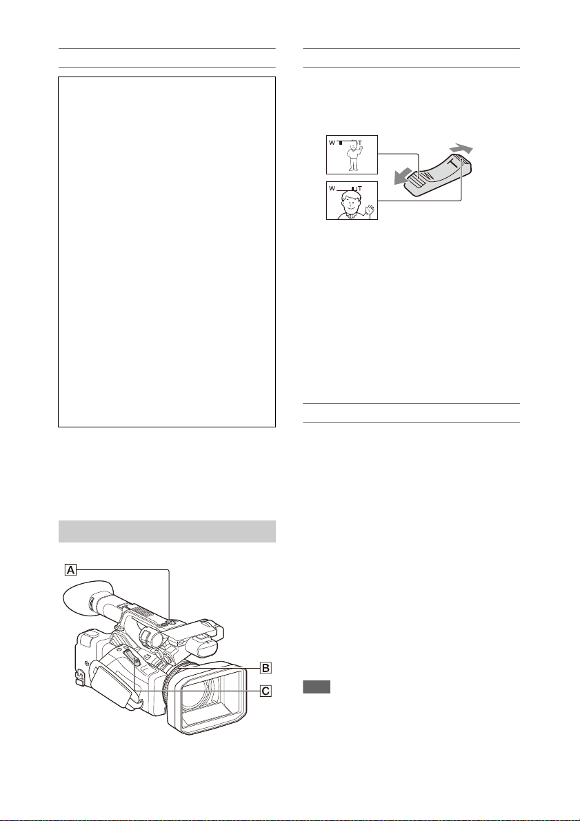
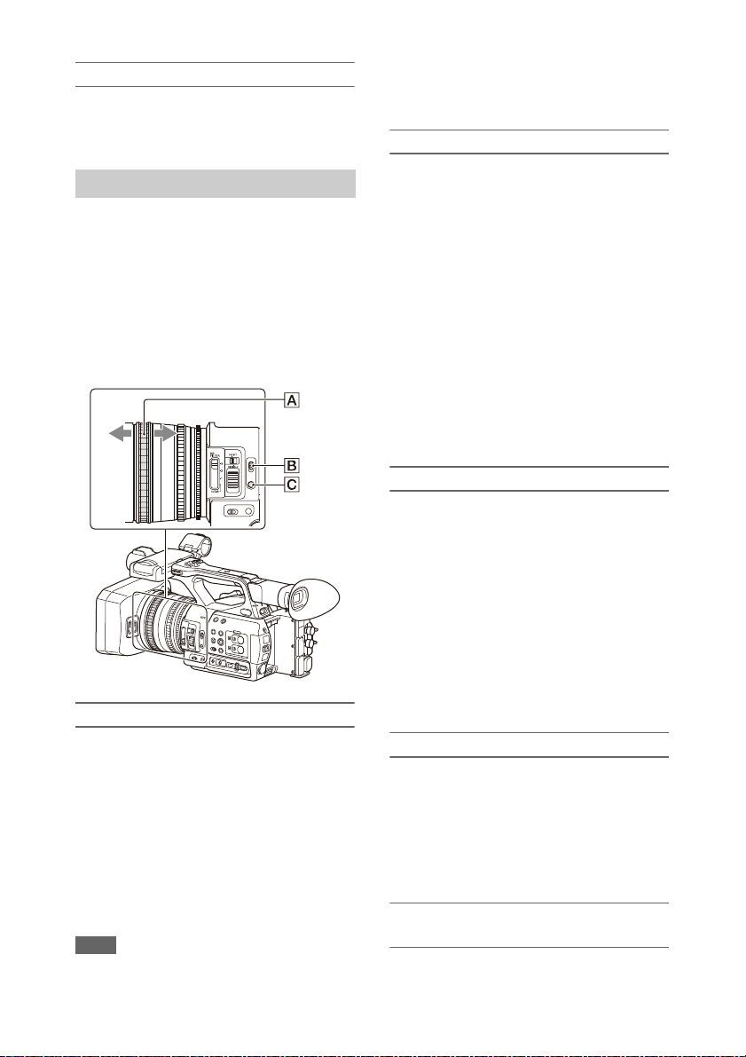
Using the power zoom lever
Zoom by pressing the power zoom lever C.
Lightly press the power zoom lever C for a
slower zoom. Fully press it for a faster zoom.
• The minimum distance required between your
camcorder and the subject for focus is about 1
cm (about 13/32 in.) for wide angle and about
80 cm (about 2 5/8 feet) for telephoto.
• The focus may not be adjusted at certain zoom
positions if the subject is within 80 cm (about 2
5/8 feet) from your camcorder.
• Keep your finger on the power zoom lever C.
If you move your finger off the power zoom
lever C, the operation sound of the power
zoom lever may also be recorded.
Using the handle zoom
To delete a clip
You can delete the last recorded clip using the
Last Clip Delete function (page 91). To delete all
clips or specific clips, perform the operation from
the thumbnail screen (page 57).
Adjusting the zoom
1. Set the handle zoom operation to “Low,”
“High,” or “Variable” using Handle Zoom
(page 71) >Setting in the Camera menu.
• When set to “Variable,” you can zoom in or
out at a variable speed according to the
pressure applied to the switch.
• When set to “Low” or “High”, you can
zoom in or out at fixed speed, regardless of
the pressure applied to the switch. You can
set the speed to “Low” or “High” using
Handle Zoom in the Camera menu.
• By assigning the Handle Zoom >Setting
function to an assignable button (page 34),
you can switch the handle zoom operation
each time the button is pressed.
2. Press the handle zoom lever A to zoom in or
out.
Note
• You cannot use the handle zoom lever A when the
handle zoom operation is set to OFF.
23
Using the zoom ring
AF/MF
mode
Full MF mode
Zoom by turning the zoom ring B.
You can zoom at the desired speed by turning the
zoom ring B. Fine adjustment is also possible.
Adjusting the focus
Tips for focusing
• Move the power zoom lever towards T
(telephoto) and adjust the focus, then, towards
W (wide angle) to adjust the zoom for
recording.
• When you want to record a close-up image of a
subject, move the power zoom lever towards W
(wide angle) to fully magnify the image, then
adjust the focus.
Adjusting in Full MF mode
Pull the focus ring A toward the back (toward
the camcorder) to activate Full MF mode for full
manual focus control.
Turn the focus ring to adjust the focus while
monitoring the image on the LCD/viewfinder
screen.
In Full MF mode, you can use the distance
markers printed on the focus ring as a guide when
adjusting the focus. The distances where the
picture is in focus correspond to the positions of
the distance markers.
Notes
• Do not use excessive force at both ends of the travel
when turning the focus ring.
• While in Full MF mode, the auto focus and push auto
focus functions do not work.
• Macro is set to off regardless of the Focus Macro
setting in the Camera menu.
Adjusting in MF mode
In MF (manual focus) mode, you can also use
auto focus operation whenever required.
Slide the focus ring A toward the front (toward
the lens hood) and set the FOCUS switch B to
MANUAL.
Using automatic focus temporarily (Push auto
focus)
In MF mode, auto focus is activated while the
FOCUS PUSH AUTO/HOLD button C of the
lens is pressed or while an assignable button
(page 34) assigned with Push AF/Push MF is
pressed.
The focus returns to manual focus when you
release the button.
This function is useful for shifting the focus from
one subject to another during manual focus mode.
Adjusting in AF mode
In AF (auto focus) mode, the focus is adjusted
automatically.
Slide the focus ring A toward the front and set
the FOCUS switch B to AUTO.
Using manual focus temporarily (Push manual
focus)
In AF mode, manual focus is activated while the
FOCUS PUSH AUTO/HOLD button of the lens
is pressed or while an assignable b utton (page 34)
assigned with Push AF/Push MF is pressed.
The focus returns to auto focus when you release
the button.
Using macro mode
In MF mode or AF mode, set Focus (page 69)
>Focus Macro in the Camera menu to On or press
an assignable button assigned with Focus Macro
(page 34) to activate macro mode to enable
focusing over a range that includes the macro
area.
Macro mode is disabled in Full MF mode.
Focusing using magnified view
(Focus Magnifier)
When an assignable button (page 34) assigned
with Focus Magnifier is pressed, the focus
24

magnifier screen appears showing the part of the
image magnified.
The magnification switches between 4× and 8×
each time the button is pressed when the
recording format is QFHD. You can move the
magnified position using the V/v/B/b button.
The center of the screen is magnified at a fixed 2×
in recording formats other than QFHD.
Press the button again to return to the normal
screen.
This function is useful for checking the focus.
Note
• Even though the image appears magnified on the
screen, the recorded image is not magnified.
Monitoring audio while shooting
Connecting a set of headphones to the headphone
jack (stereo mini jack) (page 9) enables you to
monitor the audio being recorded.
Note
• The built-in speaker is disabled while shooting
(recording or recording standby).
To adjust the audio monitoring volume
Use the VOLUME buttons (page 10).
To change the audio monitoring channel
Select the channel using Audio Output (page 78)
in the Audio menu.
Changing Basic Settings
You can change the settings based on the video
application or recording conditions.
Video format
The formats available for selection vary
depending on the system frequency and codec
settings.
Switching the system frequency
Switch using Rec Format (page 90) >Frequency
in the System menu.
The camcorder automatically restarts after
switching.
Note
• You cannot switch the system frequency during
recording or playback.
Switching the codec
Switch using Rec Format (page 90) >Codec in
the System menu.
Note
• You cannot switch the codec during recording or
playback.
Changing the format
Switch using Rec Format (page 90) >Video
Format in the System menu.
The signals from the SDI OUT and HDMI OUT
connectors are also output in the format selected
using this menu.
Note
• You cannot change the format during recording or
playback.
25
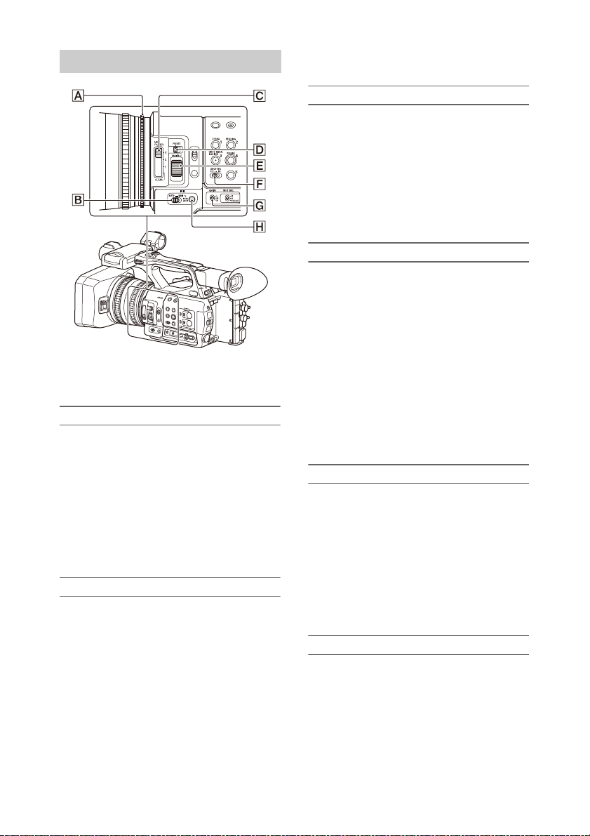
Adjusting the brightness
You can adjust the brightness by adjusting the
iris, gain, shutter speed, and by adjusting the light
level using ND filters.
Shooting using auto iris
When Full Auto mode (page 22) is on
The iris is forcibly set to Auto mode.
When Full Auto mode is off
Set the IRIS switch B to AUTO. Auto mode is
set.
The adjustment setting applied when the iris
AUTO/MANUAL switch is set to MANUAL can
also be configured using the direct menu
(page 32).
Shooting using manual iris
When Full Auto mode is off, set the IRIS switch
B to MANUAL. Manual mode is set. Turn the
iris ring A to adjust the iris.
The adjustment setting applied when the iris
AUTO/MANUAL switch is set to MANUAL can
also be configured using the direct menu
(page 32).
Switching to auto iris temporarily
In manual iris mode, press the IRIS PUSH AUTO
button H to activate the one-push auto iris
function.
Auto iris is active while the button is pressed.
Release the button to return to manual iris mode.
Shooting with auto gain (AGC)
When Full Auto mode (page 22) is on
AGC (Auto Gain Control) mode is forcibly
enabled.
When Full Auto mode is off
Set Auto Exposure >AGC (page 70) in the
Camera menu to On to activate AGC mode.
You can also set AGC on/off in the direct menu
(page 32).
Shooting with fixed gain
1. Set Full Auto mode off.
2. When the gain is automatically adjusted, set
Auto Exposure >AGC (page 70) in the
Camera menu to Off.
“AGC” disappears.
3. Set the GAIN switch G to H, M, or L.
The gain value set for the selected gain
switch position appears on the screen.
You can set the gain value for H/M/L using
Gain (page 69) in the Camera menu.
You can also set the H/M/L value in the
direct menu (page 32).
Shooting in auto shutter mode
When Full Auto mode (page 22) is on
The shutter is forcibly set to auto shutter.
When Full Auto mode is off
Set Auto Exposure >Auto Shutter (page 71) in
the Camera menu to On to activate auto shutter
speed mode.
Auto shutter can also be activated by selecting
Auto Shutter in the direct menu and setting it to
on.
Shooting with a fixed shutter
When Full Auto mode is off and Auto Exposure
>Auto Shutter (page 71) in the Camera menu is
set to Off, set the SHUTTER switch F to the ON
position to set fixed shutter with the shutter mode
and speed configured using Shutter (page 70) in
the Camera menu.
26
Setting in the Camera menu
Select Shutter (page 70) in the Camera menu and
set the shutter mode and speed.
Setting using the direct menu
You can also set ECS mode (page 70) on/off and
the shutter speed in the direct menu (page 32).
Adjusting the light level (ND filter)
You can shoot a subject with the proper
brightness by using the ND FILTER switch C
when the recording environment is too bright.
The camcorder features two ND filter modes.
You can switch the mode using the ND FILTER
mode switch D.
Preset mode
Set the ND FILTER mode switch D to PRESET,
then set the ND FILTER switch C to the
following.
CLEAR: ND filter is not used.
1: Filter density set using ND Filter >Preset1 in
the Camera menu. The default setting is 1/4.
2: Filter density set using ND Filter >Preset2 in
the Camera menu. The default setting is 1/16.
3: Filter density set using ND Filter >Preset3 in
the Camera menu. The default setting is 1/64.
Variable mode
Set the ND FILTER mode switch D to PRESET,
then set the ND FILTER switch C to the
following.
CLEAR: ND filter is not used.
1, 2, 3: You can set the filter density in a
continuous range from 1/4 to 1/128 using the ND
control dial E.
The ND FILTER switch B position (1/2/3) does
not affect the filter density adjustment.
Auto ND filter
When the ND FILTER mode switch is set to
VARIABLE and the ND FILTER switch is in
position 1 to 3, the density of the ND filter can be
adjusted automatically by setting Auto Exposure
>Auto ND Filter (page 70) in the Camera menu to
On.
You can also set Auto ND Filter on/off in the
direct menu (page 32).
When Auto ND Filter is off, you can also select
the density of the ND filter in the direct menu.
Setting auto exposure
Auto exposure control s excessive brightness t o an
appropriate level using auto ND filter, iris, gain,
and shutter functions.
Set the control mode using Auto Exposure
(page 70) >Mode in the Camera menu, and set the
level using Level.
You can also set the control mode and correction
level in the direct menu (page 32).
Using the flicker reduction function
Set Flicker Reduce (page 71) >Mode in the
Camera menu to Auto or On, and set Frequency
to the power supply frequency (50 Hz or 60 Hz).
Note
• If the frame rate for shooting is close to the power
supply frequency, flicker may not be completely
reduced when using the flicker reduction function. In
this case, use the electronic shutter.
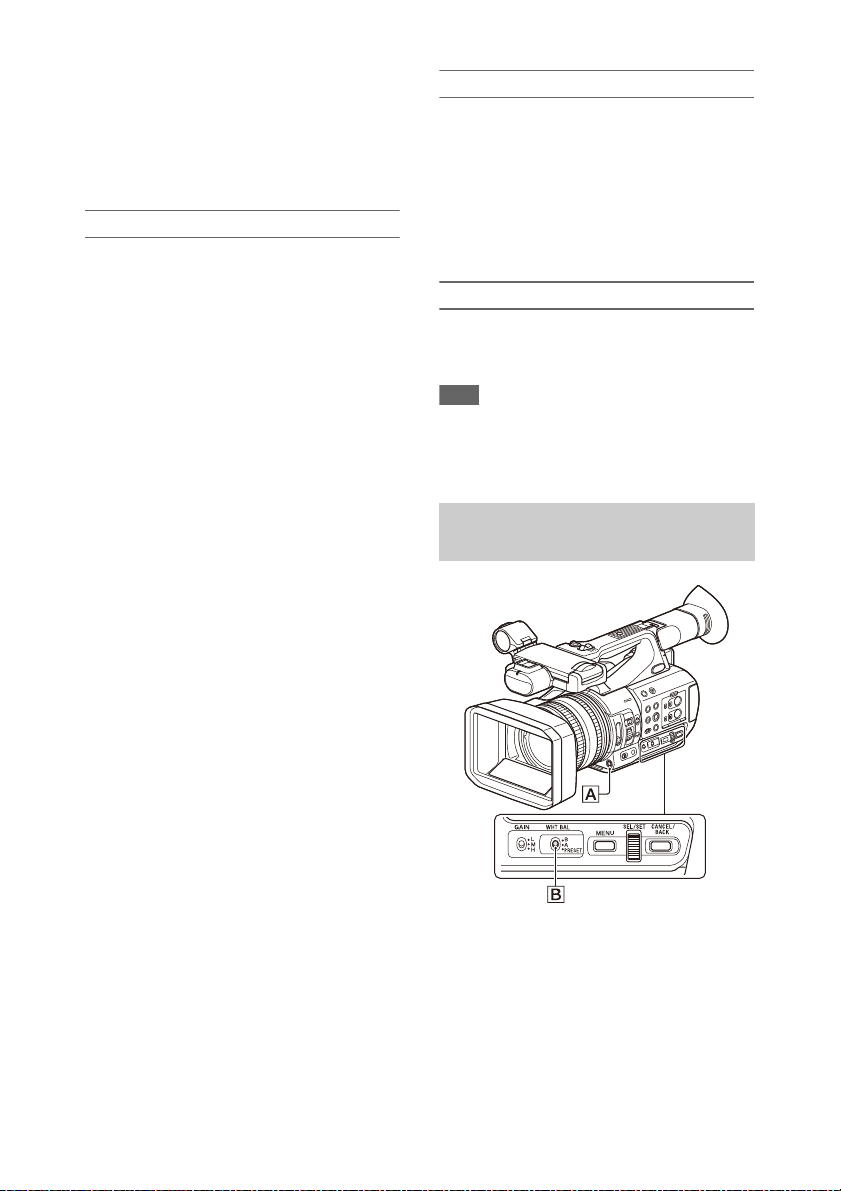
Adjusting for natural colors (white
balance)
You can select the adjustment mode to suit the
shooting conditions.
Preset mode
This mode adjusts the color temperature to a
preset value (factory de fault is 3200K). Select this
mode when you have no time to adjust the white
balance or when you wish to fix the white balance
to the preset set using White (page 73) >Preset
White in the Paint menu.
27

Memory A mode, Memory B mode
This mode adjusts the white balance to the setting
saved in memory A or B, respectively.
Press the WB SET button A to execute auto
white balance adjustment and store the adjusted
value in memory A or memory B.
ATW (Auto-Tracing White balance) mode
In this mode, the camcorder automatically adjusts
the white balance to the appropriate condition.
The white balance is automatically adjusted when
the color temperature of the light source changes.
You can select the speed of adjustment (five
steps) using White Setting >ATW Speed
(page 73) in the Paint menu.
You can freeze the current white balance setting
by assigning the ATW Hold function to an
assignable button (page 34), and pressing the
assignable button to temporarily pause ATW
mode.
Note
• It may not be possible to adjust to the appropriate
colors using ATW, depending on the lighting and
subject conditions.
Examples:
When a single color dominates the subject, such as
sky, sea, ground, or flowers.
When the color temperature is extremely high or
extremely low.
If the appropriate effect cannot be obtained because
the ATW auto tracking speed is slow or for other
reasons, run auto white balance.
Using the switch
Select the mode using the WHT BAL switch B.
B: ATW mode or Memory B mode
A: Memory A mode
PRESET: Preset mode
ATW mode is assigned to the B position of the
WHT BAL switch at the factory. You can change
the setting so that Memory B mode is selected
using White Setting >White Switch<B>
(page 73) in the Paint menu.
Setting the camcorder to Full Auto mode
(page 22) forcibly activates ATW mode.
Assigning the ATW on/off function to an
assignable button (page 34) permits you to
independently activate/deactivate ATW when
Full Auto mode is off.
Using the direct menu
Press the DISPLAY button (page 10) to display
the selected mode and color temperature on the
screen (page 11).
ATW: ATW mode
W:A: Memory A mode
W:B: Memory B mode
W:P: Preset mode
You can change the adjustment mode to the
following in the direct menu (page 32).
When the WHT BAL switch is set to the B
position, ATW mode and Memory B mode can be
set.
When the WHT BAL switch is set to the A
position, ATW mode a nd Memory A mode can be
set.
When the WHT BAL switch is set to the PRESET
position, ATW mode and Preset mode can be set.
You can set the color temperature in the direct
menu when not set to ATW mode.
You can change the color temperature in the
direct menu by selecting the color temperature
indicator. In preset mode, pressing the WB SET
button also sets the color temperature.
Switching preset mode using an
assignable button
Assign Preset White Select to an assignable
button (page 34). You can then switch preset
mode values in the order 3200K, 4300K, 5600K,
and 6300K each time you press the button.
Executing auto white balance
1 To save an adjustment value in
memory, select Memory A mode or
Memory B mode.
2 Place white paper (or other object) in a
location with the same lighting source
and conditions as the subject, then zoom
in on the paper to show white on the
screen.
3 Adjust the brightness.
Adjust the iris as described in “Shooting
using manual iris” (page 26).
28
4 Press the WB SET button A.
When you execute the adjustment in a
memory mode, the adjusted value is stored in
the memory (A or B) selected in step 1.
If auto white balance is executed in ATW
mode, the white balance adjustment returns
to the ATW mode white balance when
adjustment ends.
Notes
• Auto white balance adjustment cannot be performed
when in Preset mode.
• If the adjustment is not successful, an error message is
displayed on the screen. If the error message persists
after repeated attempts to set white balance, contact
your Sony service representative.
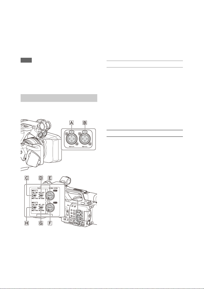
Setting the audio to record
The following connectors, switches and dials
allow you to set the sound to be recorded.
Audio source switches
CH1 (INT/EXT/MI SHOE) switch D
CH2 (INT/EXT/MI SHOE) switch G
Switches for setting the audio level
AUDIO LEVEL (CH1) dial E
AUDIO LEVEL (CH2) dial F
Refer to the block diagrams (page 110).
Using the internal microphone
You can record sound using the internal
microphone.
To record on CH1, CH2
Set the CH1 (INT/EXT/MI SHOE) switch
D and CH2 (INT/EXT/MI SHOE) switch
G to INT.
To record on CH3, CH4
Select Internal MIC using Audio Input
(page 77) >CH3 Input Select and CH4 Input
Select in the Audio menu.
Using an external audio device
Mixers and other external audio devices are
supported.
To record on CH1, CH2
External audio input connectors and selector
switches
AUDIO INPUT1 connector A
AUDIO INPUT2 connector B
INPUT1 switch C
INPUT2 switch H
1 Set the CH1 (INT/EXT/MI SHOE)
switch D and CH2 (INT/EXT/MI
SHOE) switch G to EXT.
When Audio Input >CH2 EXT Input Select
in the Audio menu is set to INPUT2, the
sound from the AUDIO INPUT1 connector
will be recorded on CH1 and the sound from
the AUDIO INPUT2 connector will be
recorded on CH2.
When CH2 EXT Input Select is set to
INPUT1, the sound from the AUDIO
INPUT1 connector will be recorded on both
CH1 and CH2.
2 Set the INPUT1/INPUT2 switches (C/
H) to LINE.
3 Connect an external audio device to the
AUDIO INPUT1/AUDIO INPUT2
connectors (A/B).
29

To record on CH3, CH4
1 Select INPUT1 using Audio Input
(page 77) >CH3 Input Select and
INPUT2 using CH4 Input Select in the
Audio menu.
If INPUT1 is selected using CH4 Input
Select, the sound from the AUDIO INPUT1
connector will be recorded on both CH3 and
CH4.
2 Perform steps 2 and 3 as described in
“To record on CH1, CH2.”
Using an external microphone
An electret condenser microphone or other
devices can be connected and used for recording.
To record on CH1, CH2
1 Set the CH1 (INT/EXT/MI SHOE)
switch D and CH2 (INT/EXT/MI
SHOE) switch G to EXT.
When Audio Input >CH2 EXT Input Select
in the Audio menu is set to INPUT2, the
sound from the AUDIO INPUT1 connector
will be recorded on CH1 and the sound from
the AUDIO INPUT2 connector will be
recorded on CH2.
When CH2 EXT Input Select is set to
INPUT1, the sound from the AUDIO
INPUT1 connector will be recorded on both
CH1 and CH2.
2 Set the INPUT1/INPUT2 switches (C/
H).
MIC: For microphone that does not require
phantom power.
MIC+48V: For microphone that requires
+48 V phantom power.
Notes
• Selecting MIC+48V and connecting a
microphone that is not compatible with a +48 V
source may damage the connected device. Check
before connecting the device.
• If noise is a concern on connectors with no device
connected, set the corresponding INPUT1/
INPUT2 switches to LINE.
3 Open the cover by pulling up the handle
of the microphone holder.
4 Attach a microphone, then close the
microphone holder to secure the
microphone.
5 Connect the microphone cable to the
AUDIO INPUT1/AUDIO INPUT2
connectors (A/B).
When you use a stereo microphone (two
XLR plugs), connect t he L (left) channel plug
to the AUDIO INPUT1 connector, and the R
(right) channel plug to the AUDIO INPUT2
connector.
To record on CH3, CH4
1 Select INPUT1 using Audio Input
(page 77) >CH3 Input Select and
INPUT2 using CH4 Input Select in the
Audio menu.
If INPUT1 is selected using CH4 Input
Select, the sound from the AUDIO INPUT1
connector will be recorded on both CH3 and
CH4.
2 Perform steps 2 to 5 as described in “To
record on CH1, CH2.”
Using a multi-interface shoe compatible
microphone
To record on CH1, CH2
1 Set the CH1 (INT/EXT/MI SHOE)
switch D and CH2 (INT/EXT/MI
SHOE) switch G to MI SHOE.
2 Attach a microphone to the multi-
interface shoe.
To record on CH3, CH4
1 Select Shoe CH1 using Audio Input
(page 77) >CH3 Input Select and Shoe
CH2 using CH4 Input Select in the
Audio menu.
2 Attach a microphone to the multi-
interface shoe.
Note
• Two microphones cannot be connected to the front and
rear Multi Interface Shoe at the same time. The first
connected microphone is the active microphone.
30
 Loading...