


 Loading...
4-693-039-13 (1)
GB
Solid-State Memory Camcorder
Operating Instructions
PXW-Z450
Software Version 3.0
© 2016 Sony Corporation

0002
Table of Contents
1. Overview |
|
Name and Function of Parts............................................... |
3 |
Screen Display................................................................... |
13 |
2. Preparation |
|
Preparing a Power Supply................................................ |
20 |
Attaching a Viewfinder..................................................... |
21 |
Using the Camcorder for the First Time........................... |
23 |
Mounting and Adjusting the Lens................................... |
24 |
Preparing the Audio Input System................................... |
25 |
Attaching and Adjusting Peripheral Devices................... |
26 |
Handling SxS Memory Cards............................................ |
27 |
Handling SD Cards for Saving Configuration Data........... |
29 |
Using a Media Adaptor..................................................... |
30 |
3. Settings and Adjustments |
|
Format Settings................................................................ |
31 |
Expansion of Imaging Dynamic Range............................ |
37 |
Adjusting the Black Balance and White Balance............. |
38 |
Setting the Electronic Shutter.......................................... |
40 |
Setting Auto Iris................................................................ |
41 |
Adjusting the Audio Level................................................ |
42 |
Setting Time Data............................................................. |
44 |
4. Shooting |
|
Basic Operations............................................................... |
46 |
Advanced Operations....................................................... |
48 |
Proxy Data......................................................................... |
53 |
Planning Metadata........................................................... |
55 |
Obtaining Location Information (GPS)............................ |
57 |
5. Network Configuration |
|
Network Functions Supported by the Camcorder........... |
58 |
Connecting Devices using Wireless LAN.......................... |
59 |
Connecting to the Internet............................................... |
63 |
Transferring Files.............................................................. |
67 |
Transmitting Streaming Video and Audio....................... |
69 |
Streaming High Quality Video.......................................... |
70 |
Using Wi-Fi Remote Control............................................ |
71 |
Configuring from the Web Menu..................................... |
73 |
Supported Network Functions and Operating |
|
Limitations................................................................ |
78 |
6. Clip Operations |
|
Clip Operations on the Thumbnail Screen....................... |
79 |
Thumbnail Menu.............................................................. |
85 |
7. Menu Display and Settings |
|
Setup Menu Organization................................................ |
86 |
Basic Setup Menu Operations.......................................... |
88 |
Editing the User Menu...................................................... |
90 |
Menu List.......................................................................... |
92 |
Assigning Functions to Assignable Switches................. |
117 |
8. Saving and Loading User Configuration Data |
|
User Configuration Data................................................. |
120 |
User Files......................................................................... |
121 |
ALL Files.......................................................................... |
122 |
Scene Files....................................................................... |
123 |
Reference Files................................................................ |
124 |
Lens Files......................................................................... |
125 |
Gamma Files................................................................... |
126 |
9. Connecting External Devices |
|
Connecting a Remote Control Unit................................ |
127 |
Connecting an External Monitor.................................... |
129 |
Managing/Editing Clips with a Computer..................... |
130 |
Configuring a Shooting and Recording System............. |
132 |
Recording External Input Signals................................... |
135 |
10. Maintenance and Inspection |
|
Maintenance................................................................... |
136 |
Error/Warning System................................................... |
137 |
11. Appendix |
|
Messages Displayed During Operation.......................... |
140 |
Items Saved in User Data................................................ |
146 |
Special Recording Support by Recording Format.......... |
156 |
Picture Cache Rec Mode Settings................................... |
157 |
Usage Precautions.......................................................... |
158 |
Specifications.................................................................. |
160 |

0003 1. Overview
Name and Function of Parts
Power Supply
6
12
1.LIGHT (video light) switch
Determines how a video light connected to the LIGHT connector (page 4) is turned on and off. AUTO: When the POWER switch of the video light
is in the on position, the video light is turned on automatically while the camcorder is recording.
MANUAL: You can turn the video light on or off manually, using its own switch.
[Note]
When the camcorder is set for recording in Picture Cache Rec mode, it is not possible to turn on the light before operation to start recording is carried out (or while data is being stored in memory).
3 4 5
2. POWER switch
Turns the main power supply on ( ) and off ( ).
3.DC IN (DC power input) connector (XLR type, 4-pin, male)
4.DC OUT 12V (DC power output) connector (4-pin, female)
Supplies power for an optional WRR855S/860C/861/862 UHF Synthesizer Diversity Tuner or HDVF-L750 Viewfinder (maximum 1.8 A).
[Note]
Do not connect any equipment other than the UHF synthesized diversity tuner.
5. Battery attachment shoe
Attach a BP-FLX75 Battery Pack. Alternatively, you can attach an AC-DN2B/DN10 AC Adaptor to operate the camcorder from an AC power supply.
“Preparing a Power Supply” (page 20)
[Note]
For your safety, and to ensure proper operation of the camcorder, Sony recommends the use of the BP-FLX75 Battery Pack.
6. Camera adaptor connector
Enables connection of a CA-TX70/FB70 HD Camera Adaptor. To connect an adaptor, remove the cover.
[Note]
Not supported in the return video display by the camcorder.
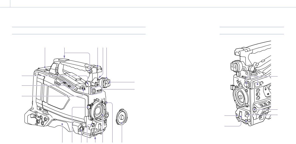
0004 1. Overview: Name and Function of Parts
Accessory Attachments
1 |
2 |
3 4 5 |
9 |
6 |
|
10 |
||
7 |
||
|
11 


 8
8
12 13
1. Wireless receiver insertion slot (page 25)
“Attaching a Wireless Receiver” (page 25)
2.Shoulder strap fitting (page 26)
3.Accessory shoe (page 26)
4.Viewfinder front-to-back positioning lever (page 21)
5.Viewfinder left-to-right positioning ring (page 21)
6.Viewfinder attachment shoe (page 21)
14 15 16 17 18 19
7.VF (viewfinder) connectors (26-pin, rectangular and 20-pin, round)
The analog interface connector (20-pin) is for connection of an HDVF series viewfinder, and the digital interface connector (26-pin) is for connection of a CBK-VF02 HD viewfinder. Connect a viewfinder connection cable to the connector compatible with the viewfinder being used.
[Notes]
ˎˎDo not connect viewfinders to both connectors at the same time.
ˎˎWhen connecting or disconnecting an interface cable to this connector, power off the camcorder first.
8. Lens mount securing rubber
After locking the lens in position using the lens locking lever, fit this rubber over the lower of the two projections. This fixes the lens mount, preventing it from coming loose.
9.Viewfinder front-to-back positioning knob (page 21)
10.Attachment for optional microphone holder (page 25)
11.LIGHT (video light) connector (2-pin, female) (page 26)
12.Shoulder pad (page 26)
13.Lens cable clamp
Clamps the lens cable.
14.MIC IN (microphone input) (+48 V) connector (XLR type, 5-pin, female)
Connect a stereo microphone to this connector. The power (+48 V) is supplied via this connector.
15. LENS connector (12-pin) (page 24)
[Note]
When connecting or disconnecting the lens cable to this connector, power off the camcorder first.
16. Tripod mount
When using the camcorder on a tripod, attach the tripod adaptor (optional).
17.Lens mount (special bayonet mount) (page 24)
18.Lens locking lever (page 24)
19.Lens mount cap
Remove by pushing the lens locking lever up. When no lens is mounted, keep this cap fitted for protection from dust.
Controls Near the Lens
3 |
|
4 |
1 |
5 |
|
2  6
6
1.REC START (recording start) button
Press to start recording. Press it again to stop recording. The operation is the same as that of the VTR button on the lens.
2.SHUTTER switch
Set to ON to use the electronic shutter. Push to SELECT to switch the shutter speed or shutter mode setting. When this switch is operated, the new setting appears on the viewfinder screen for about three seconds.
“Setting the Electronic Shutter” (page 40)
0005 1. Overview: Name and Function of Parts
[Note]
If Flash Band Reduce is On, setting the SHUTTER switch to ON turns off the Flash Band Reduce function and the FBR indicator disappears from the viewfinder screen.
Subsequently, setting the SHUTTER switch to OFF turns on the Flash Band Reduce function and the FBR indicator reappears on the viewfinder screen.
3. FILTER knob
Switches between four ND filters built into this camcorder.
When this selector is used, the new setting appears on the viewfinder screen for about three seconds.
FILTER knob |
ND filter |
setting |
|
1CLEAR
21/4 ND (attenuates light to approximately 1/4)
31/16 ND (attenuates light to approximately 1/16)
41/64 ND (attenuates light to approximately 1/64)
You can change a Maintenance menu setting so that different white balance settings can be stored for different FILTER knob positions. This allows you to automatically obtain optimum white balance for the current shooting conditions in linkage with the filter selection.
“Adjusting the White Balance” (page 38)
4. MENU knob (page 88)
5. AUTO W/B BAL (automatic white/black |
LCD Monitor Side (1) |
|
|
|
|
|
balance adjustment) switch |
|
|
|
|
||
Activates the automatic white/black balance |
|
|
|
|
|
|
adjustment functions. |
1 |
2 |
3 |
4 |
5 |
|
WHITE: Adjust the white balance automatically. |
||||||
|
|
|
|
|
||
If the WHITE BAL switch (page 6) is set |
|
|
|
|
|
|
to A or B, the white balance setting is stored |
|
|
|
|
|
|
in the corresponding memory. If the WHITE |
|
|
|
|
|
|
BAL switch is set to PRST, the automatic |
|
|
|
|
|
|
white balance adjustment function does not |
|
|
|
|
|
|
operate. |
|
|
|
|
|
|
BLACK: Adjust the black set and black balance |
|
|
|
|
|
|
automatically. |
|
|
|
|
|
|
You can use the AUTO W/B BAL switch even when |
|
|
|
|
|
|
the ATW (Auto Tracing White Balance) function is |
|
|
|
|
|
|
operating. |
|
|
|
|
|
|
If you push the switch to the WHITE side once |
|
|
|
|
|
|
more during the automatic white balance |
|
|
|
|
|
|
adjustment, the adjustment is canceled and |
|
|
|
|
|
|
the white balance setting returns to the original |
|
|
|
|
|
|
setting. |
|
|
|
|
|
|
If you push the switch to the BLACK side once |
|
|
|
|
|
|
more during the automatic black balance |
|
|
|
|
|
|
adjustment, the adjustment is canceled and |
|
|
|
|
|
|
the black balance setting returns to the original |
|
|
|
|
|
|
setting. |
|
|
|
|
|
6. MIC (microphone) LEVEL knob (page 42)
|
6 |
7 8 9 |
|
10 |
12 |
11 |
12 |
13
 14
14

0006 1. Overview: Name and Function of Parts
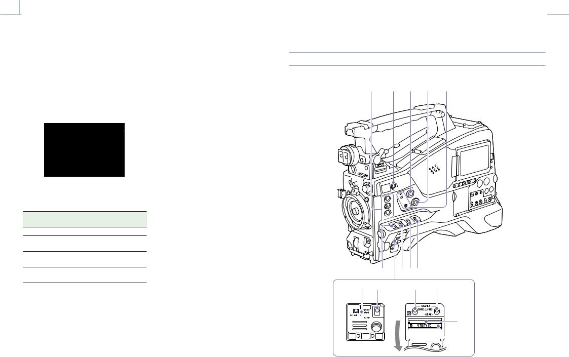
1.ASSIGN. (assignable) 1/2/3 switches
You can assign a function using Operation >Assignable Switch in the setup menu (page 117).
The ASSIGN. 1/3 switches are provided with an indicator to show whether a function is assigned to the switch (ON) or not (OFF).
2.ONLINE button
When network client mode or the streaming function is assigned to this button, press and hold until the indicator is lit orange. Then, press the button again, turning the indicator blue, to enable network client mode or the streaming function. To exit the enabled function, press and hold the button until the indicator turns off.
The button can also be used as an assignable switch when assigned with functions other than those above (page 118).
3.ALARM (alarm tone volume adjustment) knob
Controls the volume of the warning tone that is output via the built-in speaker or optional earphones. When the knob is turned to the minimum position, no sound can be heard. However, if Maintenance >Audio >Min Alarm
Volume in the setup menu is set to [Set], the alarm tone is audible even when this volume control is at the minimum position.
ALARM
Minimum Maximum
4.MONITOR (monitor volume adjustment) knob
Controls the volume of the sound other than the warning tone that is output via the built-in speaker or earphones. When the knob is turned to the minimum position, no sound can be heard.
5. MONITOR (audio monitor selection) switches
By means of combinations of the two switches, you can select audio that you want to hear through the built-in speaker or earphones.
When the lower switch is set to CH-1/2
Upper switch |
Audio output |
CH-1/CH-3 |
Channel 1 audio |
MIX |
Channels 1 and 2 mixed audio |
|
(stereo)a) |
CH-2/CH-4 |
Channel 2 audio |
When the lower switch is set to CH-3/4 |
|
|
|
Upper switch |
Audio output |
CH-1/CH-3 |
Channel 3 audio |
MIX |
Channels 3 and 4 mixed audio |
|
(stereo)a) |
CH-2/CH-4 |
Channel 4 audio |
a)By connecting stereo headphones to the EARPHONE jack, you can hear the audio in stereo. (Maintenance >Audio >Headphone Out in the setup menu must be set to Stereo.)
6. ASSIGN. (assignable) 0 switch
You can assign a function using Operation >Assignable Switch in the setup menu (page 117).
Off is assigned to these switches when the camcorder is shipped from the factory.
This is a momentary type switch. Each press of the switch turns the function assigned to this switch on or off.
7. GAIN switch
Switches the gain of the video amplifier to match the lighting conditions during shooting. The gain values corresponding to the L, M, and H settings can be selected using Operation >Gain Switch in the setup menu (page 96) (factory settings are L=0 dB, M=6 dB, and H=12 dB).
When this switch is adjusted, the new setting appears on the viewfinder screen for about three seconds.
8.OUTPUT/DCC (output signal/dynamic contrast control) switch
Switches the video signal output from the camera module, between the following two.
BARS: Output the color bar signal.
CAM: Output the video signal being shot. When this is selected, you can switch DCC 1) on and off.
1)DCC (Dynamic Contrast Control): Against a very bright background with the iris opening adjusted to the subject, objects in the background will be lost in the glare. The DCC function will suppress the high intensity and restore much of the lost detail. It is particularly effective for shooting in the following cases.
ˎˎShooting people in the shade on a sunny day
ˎˎShooting a subject indoors, against a background through a window
ˎˎAny high contrast scene
9. WHITE BAL (white balance memory) switch
Controls adjustment of the white balance. PRST: Adjust the color temperature to the preset
value (the factory default setting: 3200K). Use this setting when you have no time to adjust the white balance.
A or B: Recall the white balance adjustment settings already stored in A or B. Push the AUTO W/B BAL switch (page 5) to the WHITE position to automatically adjust the white balance and save the adjustment settings in memory A or memory B.
B (ATW 1)):When this switch is set to B and Operation >White Setting >White Switch <B> is set to [ATW] in the setup menu, ATW is activated.
You can use the AUTO W/B BAL switch even when ATW is in use.
When this switch is adjusted, the new setting appears on the viewfinder screen for about three seconds.
1)ATW (Auto Tracing White balance): The white balance of the picture being shot is adjusted automatically for varying lighting conditions.
[Note]
It may not be possible to adjust to the appropriate colors using ATW, depending on the lighting and subject conditions.
Examples:
ˎˎWhen a single color dominates the subject, such as sky, sea, ground, or flowers.
ˎˎWhen the subject is under a light source of extremely high or extremely low color temperature.
If execution of automatic tracing by the ATW function takes an unacceptably long time or only results in an inadequate effect, then execute the AWB function.
10. Switch cover
Open this cover to use the MENU ON/OFF switch or the MENU CANCEL/PRST/ESCAPE switch.
11. MENU ON/OFF switch
To use the switch, open the cover.
This switch is used to display the menu on the viewfinder screen or the test signal screen. Each time the switch is pushed down, the menu screen is turned on and off.
The function of this switch is the same as that of the MENU button in the thumbnail screen operations section.
[Note]
It is not possible to turn off the menu screen by closing the cover.
12. MENU CANCEL/PRST (preset) /ESCAPE switch
To use the switch, open the cover.
This switch has different functions depending on whether or not a menu is displayed.
Use the switch in the following way when the menu is displayed.
CANCEL/PRST: Pushing this switch up to this position after a setting is changed in the setup menu displays the message to confirm whether the previous settings are canceled. Pushing this switch up to this position again cancels the previous settings.
Pushing this switch up to this position before a setting is changed in the setup menu or after a setting change is canceled in the setup menu displays the message to confirm whether the setting is reset to the initial value. Pushing
this switch up to this position again resets the
0007 1. Overview: Name and Function of Parts
settings to the initial value. |
LCD Monitor Side (2) |
|
|
|
|
ESCAPE: Use this switch when the menu page, |
|
|
|
||
which has a hierarchical structure, is opened. |
|
|
|
|
|
Each time the switch is pushed to this position, |
|
|
|
|
|
the page returns to one stage higher in the |
|
|
|
|
|
hierarchy. |
|
|
|
|
|
Use the switch in the following way when the |
[1] |
[2] |
|
|
|
7 |
8 |
9 |
|||
menu is not displayed. |
|
||||
CANCEL/PRST: Each time this switch is pushed |
|
|
|
|
|
upward, a window to confirm the menu |
|
|
|
|
|
settings and status of the camcorder appears |
|
|
|
|
|
on the viewfinder screen (page 13). The |
|
|
|
|
|
window consists of several pages, which are |
|
10 |
11 |
12 |
|
switched each time the switch is pushed |
|
||||
|
|
|
|
||
upward. |
|
|
|
|
|
ESCAPE: To clear the page, push this switch down |
|
|
|
|
|
to the OFF position. |
|
|
|
|
|
13. UTILITY SD card slot |
|
|
|
1 |
|
Insert an SD card for saving camcorder settings. |
|
|
|
||
14. ACCESS indicator |
|
|
|
2 |
|
Lights up orange when the SD card is being |
|
|
|
||
accessed. |
|
|
|
3 |
|
|
|
|
|


 4
4
5
6
13 14 15 16 17
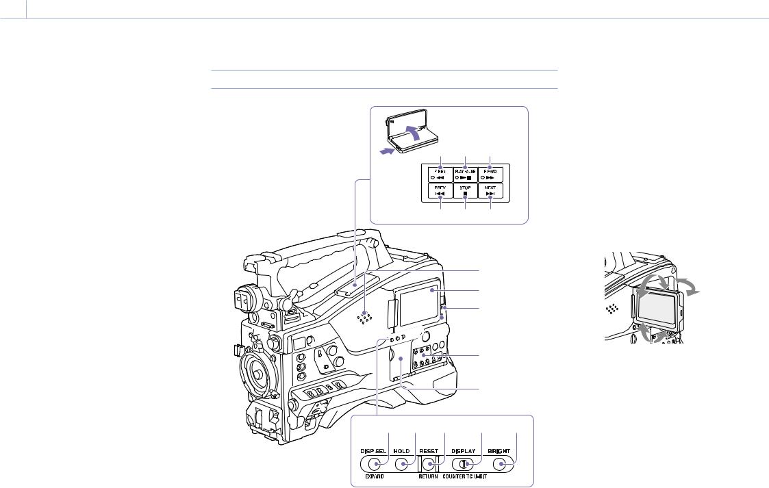
1. Built-in speaker
The speaker can be used to monitor E-E 1) sound during recording, and playback sound during playback. The speaker also sounds alarms to reinforce visual warnings (page 137).
If you connect earphones to the EARPHONE jack, the speaker output is suppressed automatically.
1)E-E: Abbreviation of “Electric-to-Electric.” In E-E mode, video and audio signals input to the camcorder are output after passing through internal electric circuits only. This can be used to check input signals.
2. LCD monitor
Displays remaining battery capacity, remaining media capacity, audio levels, time data, and so on. It also allows you to check camera and playback pictures (page 13).
You can adjust the position and angle of the LCD monitor.
3. WARNING indicator
Lights up or flashes when an abnormality occurs (page 137).
4. ACCESS indicator
Lights up in blue when data is written to or read from the recording media.
5.Audio control section (page 9)
6.Thumbnail screen operation section (page 9)
7.F REV (fast reverse) button and indicator
This plays back at high speed in the reverse
direction. The playback speed changes in the order ×4 ×15 ×24 with each press of the button.

0008 1. Overview: Name and Function of Parts
The indicator lights during high-speed playback in the reverse direction.
8. PLAY/PAUSE button and indicator
Press this button to view playback video images using the viewfinder screen or the LCD monitor. The indicator lights during playback.
Press this button again during playback to pause, outputting a still image. At this time the indicator flashes at a rate of once per second.
Pressing the F REV or F FWD button during playback or pause starts high speed playback in the forward or reverse direction.
9.F FWD (fast forward) button and indicator
This plays back at high speed in the forward
direction. The playback speed changes in the order ×4 ×15 ×24 with each press of the button. The indicator lights during high-speed playback in the forward direction.
10.PREV (previous) button
This jumps to the first frame of the current clip. If you press this together with the F REV button, the jump is to the first frame of the first recorded clip on the recording media.
If you press this button twice in rapid succession, the jump is to the first frame of the preceding clip (or the first frame of the current clip when no preceding clips exist).
11. STOP button
Press this button to stop playback.
12. NEXT button
This jumps to the first frame of the next clip.
If you press this together with the F FWD button, the jump is to the last frame of the last recorded clip on the recording media.
13.DISP SEL (display selection)/EXPAND (expand function) button
With each press of this button, the display in the LCD monitor changes as follows.
Display indication |
Description |
Video with |
The LCD monitor displays |
superimposed |
the same text information as |
information (CHAR) |
the viewfinder. |
Video without |
Only the video appears. |
superimposed |
|
information (MONI) |
|
Status display |
Counter indications, |
(STATUS) |
warnings, audio levels, and |
|
similar information appear. |
|
No video image appears. |
The EXPAND button function will be supported in a future upgrade.
14. HOLD (display hold) button
Pressing this button instantly freezes the time data displayed in the LCD monitor. (The timecode generator continues running.) Pressing this button again releases the hold.
For details about the time data display, see page 13.
15. RESET/RETURN button
Resets the value shown in the time data display in the LCD monitor. According to the settings of the PRESET/REGEN/CLOCK switch (page 9) and the F-RUN/SET/R-RUN switch (page 9), this button resets the display as follows.
Switch settings |
RESET/RETURN button |
|
operation |
DISPLAY switch: |
Reset counter to 00:00:00:00. |
COUNTER |
|
DISPLAY switch: |
Reset timecode to |
TC |
00:00:00:00. |
PRESET/REGEN/ |
|
CLOCK switch: |
|
PRESET |
|
F-RUN/SET/R-RUN |
|
switch: |
|
SET |
|
Switch settings |
RESET/RETURN button |
|
operation |
DISPLAY switch: |
Reset user bits data a) to |
U-BIT |
00:00:00:00. |
PRESET/REGEN/ |
|
CLOCK switch: |
|
PRESET |
|
F-RUN/SET/R-RUN |
|
switch: |
|
SET |
|
a)Of the timecode bits for every frame recorded on the media, those bits which can be used to record useful information for the user such as scene number, shooting place, etc.
“Setting Time Data” (page 44)
This button returns to the previous screen when pressed during thumbnail screen display or essence mark thumbnail screen display.
16. DISPLAY switch
This cycles the data displayed in the time data display in the LCD monitor through the sequence COUNTER, TC, and U-BIT (page 13).
COUNTER: Display recording/playback duration counter.
TC: Display timecode. U-BIT: Display user bits data.
17. BRIGHT (brightness) button
Switches the brightness of the LCD monitor backlight.
Each press of the button selects the next setting in the order shown in the following table. If you press the button with the LCD monitor off, the LCD backlight comes on in the H state.
Setting LCD monitor backlight
HHigh (select this to view the LCD monitor outdoors in the daytime)
M |
Brightness between H and L |
LLow (select this to view the LCD monitor indoors or outdoors at night)
OFF |
Off (the display is also off) |

0009 1. Overview: Name and Function of Parts
Thumbnail screen operations section and audio control section
1 |
2 |
3 |
4 |
5 |
|
|
|
|
|
6 |
7 |
|
|||||||||||||||
|
|
|
|
|
|
|
|
|
|
|
|
|
|
|
|
|
|
|
|
|
|
|
|
|
|
|
|
|
|
|
|
|
|
|
|
|
|
|
|
|
|
|
|
|
|
|
|
|
|
|
|
|
|
|
|
|
|
|
|
|
|
|
|
|
|
|
|
|
|
|
|
|
|
|
|
|
|
|
|
|
|
|
|
|
|
|
|
|
|
|
|
|
|
|
|
|
|
|
|
|
|
|
|
|
|
|
|
|
|
|
|
|
|
|
|
|
|
|
|
|
|
|
|
|
|
|
|
|
|
|
|
|
|
|
|
|
|
|
|
|
|
|
|
|
|
|
|
|
|
|
|
|
|
|
|
|
|
|
|
|
|
|
|
|
|
|
|
|
|
|
|
|
|
|
|
|
|
|
|
|
|
|
|
|
|
|
|
|
|
|
|
|
|
|
|
|
|
|
|
|
|
|
|
|
|
|
|
|
|
|
|
|
|
|
|
|
|
|
|
|
|
|
|
|
|
|
|
|
|
|
|
|
|
|
|
|
|
|
|
|
|
|
|
|
|
|
|
|
|
|
|
|
|
|
|
|
|
|
|
|
|
|
|
|
|
|
|
|
|
|
|
|
|
|
|
|
|
|
|
|
|
|
|
|
|
|
|
|
|
|
|
|
|
|
|
|
|
|
|
|
|
|
|
|
|
|
|
|
|
|
|
|
|
|
|
|
|
|
|
|
|
|
|
|
|
|
|
|
|
|
|
|
|
|
|
8 |
9 |
1011 |
12 |
1. Thumbnail indicator
This lights when the thumbnail screen is displayed.
2. THUMBNAIL button
Press this button to display the thumbnail screen (page 79) and to carry out a thumbnail operation.
Press once more to return to the original display.
3. SET button and arrow buttons
Use these buttons to make timecode and user bit settings, and for thumbnail screen operations. When the menu is displayed, press this button to select an item or to confirm the setting change.
4. MENU button
Each press of this button turns the setup menu display on and off.
The function of this button is the same as that of the MENU ON/OFF switch.
5.F-RUN/SET/R-RUN (free run/set/recording run) switch
Selects the operating mode of the internal timecode generator. The operating mode is set as explained below, depending on the position of the switch.
F-RUN: Timecode keeps advancing, regardless of whether the camcorder is recording. Use this setting when synchronizing the timecode with external timecode.
SET: Sets the timecode or user bits.
R-RUN: Timecode advances only during recording. Use this setting to have a consecutive timecode on the recording media.
“Setting the Timecode” (page 44)
“Setting the User Bits” (page 44)
6.LEVEL CH1/CH2/CH3/CH4 (audio channel 1/2/3/4 recording level) knobs
Adjust the audio levels to be recorded on channels 1, 2, 3, and 4 when the AUDIO SELECT CH1/CH2 and AUDIO SELECT CH 3-4 switches are set to MANUAL.
7.AUDIO SELECT CH 3-4 (audio channel 3/4 adjustment method selection) switches
Select the audio level adjustment method for audio channels 3 and 4.
AUTO: Automatic adjustment MANUAL: Manual adjustment
8. ESSENCE MARK button
By pressing this button when a thumbnail display is on the screen, you can view the following thumbnail displays of the essence-marked frames of the selected clip, depending on the item selected in a list displayed on the screen.
All: Thumbnail display of all frames marked with essence marks.
Rec Start: Thumbnail display of frames marked with Rec Start marks and of the first frames of clips (when the first frames are not marked with Rec Start marks).
Shot Mark1: Thumbnail display of the frames marked with Shot Mark 1.
Shot Mark2: Thumbnail display of the frames marked with Shot Mark 2.
You can also select Shot Mark 0 and Shot Mark 3 to Shot Mark 9.
If a clip is recorded using planning metadata that defines names for shot mark 0 to shot mark 9, the selection options in the list are displayed by the defined names.
9. SHIFT button
Use this in combination with other buttons.
10.PRESET/REGEN (regeneration)/CLOCK switch
Selects the type of timecode to record. PRESET: Record new timecode on the media. REGEN: Record timecode continuous with the
existing timecode recorded on the media. Regardless of the setting of the F-RUN/SET/R- RUN switch, the camcorder operates in R-RUN mode.
CLOCK: Record timecode synchronized to the internal clock. Regardless of the setting of the F-RUN/SET/R-RUN switch, the camcorder operates in F-RUN mode.
11.AUDIO SELECT CH1/CH2 (audio channel 1/2 adjustment method selection) switches
Select the audio level adjustment method for audio channels 1 and 2.
AUTO: Automatic adjustment MANUAL: Manual adjustment
12.AUDIO IN CH1/CH2/CH3/CH4 (audio channel 1/2/3/4 input selection) switches
Select the audio input signals to be recorded on audio channels 1, 2, 3 and 4.
FRONT: Audio input signals from the microphone connected to the MIC IN connector
REAR: Audio input signals from an audio device connected to the AUDIO IN CH-1/CH-2 connectors
WIRELESS: Audio input signals from the UHF portable tuner if it is attached
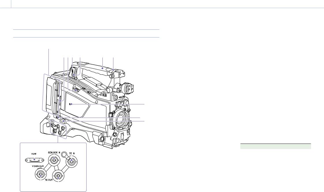
0001 1. Overview: Name and Function of Parts
Handle and Memory Card Slot Side
SxS memory card slots (page 27)
6 5 4 |
3 |
2 |
1 |
7
8 9
10 |
11 |
12 |
|
|
|
|
|
|
|
|
|
|
|
|
|
|
|
|
|
|
|
|
|
|
|
|
|
|
|
|
|
|
|
|
|
|
|
|
|
|
|
|
|
|
|
|
|
|
|
|
|
|
|
|
|
|
|
|
|
|
|
|
|
|
|
|
|
|
|
|
|
|
|
|
|
|
|
|
|
|
|
|
|
|
|
|
|
|
|
|
|
|
|
|
|
|
|
|
|
|
|
|
|
|
|
|
|
|
|
|
|
|
|
|
|
|
|
|
|
|
|
|
|
|
|
|
|
|
|
|
13 |
|
14 |
|
|
|||||||||||
1. ASSIGNABLE 4/5 switches |
|
|
|
camcorder is shipped from the factory. |
|||||||||||
You can assign a function using Operation |
2. GPS module |
||||||||||||||
>Assignable Switch in the setup menu |
|||||||||||||||
Contains a built-in GPS module. |
|||||||||||||||
(page 118). |
|
|
|
||||||||||||
|
|
|
|
||||||||||||
Off is assigned to these switches when the |
“Obtaining Location Information (GPS)” (page 57) |
||||||||||||||
[Note]
Do not grasp this part of the camcorder when the GPS function is in use.
3. PC connector
Used to put this camcorder into USB connection mode and use it as an external storage device for a computer. When a computer is connected to this connector, every memory card inserted in the camcorder is recognized as a drive on the computer.
4. External device connector
Connect to a PSZ-HA50 Portable Storage HDD (option), PSZ-SA25 Portable Storage SSD (option), a general-purpose external USB HDD, or USB flash drive to copy clips from the recording media inserted in an SxS card slot of the camcorder to USB media.
[Note]
This connector should be used only for connecting the type of devices above. It cannot be used for connecting a USB hub or other devices.
5. USB wireless LAN module connector
Connect to an IFU-WLM3 USB Wireless LAN Module (supplied), CBK-WA02 Wireless LAN Adaptor (option), or combination of CBK-NA1 Network Adaptor Kit (option) and modem (option) to enable communications with wireless LAN devices and networks.
“Connecting Devices using Wireless LAN” (page 59)
“Connecting to the Internet” (page 63)
6. PROXY SD card slot (page 53)
Insert an SD card for recording proxy data.
7.  (NFC) mark
A built-in NFC antenna is provided.
8.SLOT SELECT (SxS memory card select) button
When SxS memory cards are loaded in both card slots A and B, press this button to select the card you want to use (page 28).
9. Network connector
Connects to a network via a wired LAN connection using a LAN cable (sold separately).
[CAUTION]
ˎˎFor safety, do not connect the connector for peripheral device wiring that might have excessive voltage to this port.
Follow the instructions for this port.
ˎˎWhen you connect the LAN cable of the unit to peripheral device, use a shielded-type cable to prevent malfunction due to radiation noise.
“Connecting to the Internet” (page 63)
10. HDMI connector
Connect an HDMI device, such as a monitor or recording unit, to output HD or SD HDMI video and audio signals.
[Note]
4K (QFHD) output is not supported.
11. GENLOCK IN (genlock signal input) connector (BNC type)
This connector inputs a reference signal when the camcorder is to be genlocked or when timecode is to be synchronized with external equipment.
The supported reference signals vary depending on the current system frequency as shown in the following table.
System frequency |
Supported reference signals |
59.94i |
1080/59.94i, 480/59.94i |
59.94P |
1080/59.94i, 480/59.94i |
50i |
1080/50i, 576/50i |
50P |
1080/50i, 576/50i |
29.97P |
1080/59.94i, 480/59.94i |
25P |
1080/50i, 576/50i |
23.98P |
1080/23.98PsF |
12. TC IN (timecode input) connector (BNC type)
To apply an external lock to the timecode of the camcorder, input the reference timecode.
“Setting the Timecode” (page 44)
13. VIDEO OUT connector (BNC type)
Outputs video signals for monitoring.
00011 1. Overview: Name and Function of Parts
14.TC OUT (timecode output) connector (BNC type)
To lock the timecode of an external VTR to the timecode of this camcorder, connect this
connector to the external VTR’s timecode input connector.
Tally Indicator and Connector Section
1
2
3 |
4 |
5 |
6 |
LINE |
AES/ |
MIC |
LINE |
AES/ |
MIC |
|
EBU |
EBU |
|
||||
|
|
+48V |
|
|
+48V |
|
|
|
OFF |
|
|
OFF |
SDI IN |
|
|
|
|
|
|
12V 1.8A
1 |
3 |
SDI OUT |
SDI OUT |
2 |
4 |
CH1 |
CH2 |
|
|
1/2 |
3/4 |
|
|
|
AUDIO IN |
AUDIO OUT |
REMOTE |
1 7 |
8 |
9 |
10 |
11 |
1. TALLY (back tally) indicator (red)
Lights up during recording. It will not light if the TALLY switch is set to OFF. It also flashes when the WARNING indicator operates. The tally indicator on the front of the viewfinder and the REC indication on the viewfinder screen light or flash in the same manner.
“Error/Warning System” (page 137)
2. TALLY switch
Set to ON to activate the TALLY indicator function.
3. EARPHONE jack (stereo, mini jack)
You can monitor the E-E sound during recording and playback sound during playback. When an alarm is indicated, you can hear the alarm sound through the earphone. Plugging an earphone into the jack automatically cuts off the built-in speaker. You can select monaural or stereo using Maintenance >Audio >Headphone Out in the setup menu.
[Note]
Use monaural (2-pole) or stereo (3-pole) type earphones. Use of other earphones may damage the camcorder.
4. AUDIO IN selector switch
Select the audio source you connect to the AUDIO IN CH1/CH2 connectors.
LINE: When connecting a stereo amplifier or other external audio signal source
AES/EBU: When connecting an external digital audio signal source
MIC: When connecting a microphone.
5.+48V/OFF (+48V external power source on/ off) switch
Switch between the following settings, according to the microphone used for audio input.
+48V: Microphone requiring external power source (phantom power)
OFF: Microphone using internal power source or not requiring a power source
6. SDI IN (SDI input) connector (BNC type)
Connector used when connecting an external SDI signal source to the camcorder.

00012 1. Overview: Name and Function of Parts
7.AUDIO IN CH-1/CH-2 (audio channel 1 and channel 2 input) connectors (XLR type, 3-pin,
female)
Connect to audio equipment or a microphone.
8. Bottom cover
This is provided for protecting the cables connected to the connectors on the rear panel. By loosening the screws which retain the cover to the bottom of the camcorder, you can adjust the position of the cover depending on the size and shape of the microphone or audio cable plugs. After adjusting the position, tighten the screws to secure the cover.
9.AUDIO OUT connector (XLR type, 5-pin, male)
Outputs the audio signals recorded on audio channels 1 and 2 or audio channels 3 and 4. The audio signals are selected by the MONITOR switch.
10. REMOTE connector (8-pin)
Connect a remote control unit to control the camcorder remotely.
[Note]
Before connecting/disconnecting the Remote Control Unit to/from the camcorder, be sure to turn off the camcorder POWER switch.
11. SDI OUT 1/2/3/4 connectors (BNC type)
Outputs a 3G/HD SDI or SD SDI signal (with embedded audio). The output from this connector can be turned on/off using Operation >Input/ Output >SDI Out1/3 Output or SDI Out2/4 Output in the setup menu.
00013 1. Overview
Screen Display
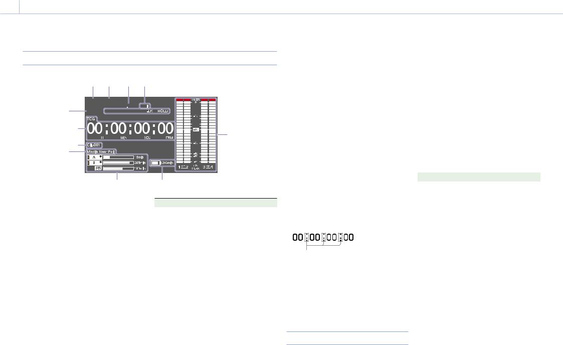
Information Screen
1 2 3 4 5
12 13


11 |
6 |
|
910 |
||
|
||
8 |
7 |
1.File system indicator
2.File format indicator
3.Status display
PB: Appears during media playback.
NDF: Appears when non-drop-frame timecode is selected.
EXT-LK: Appears when the internal timecode generator is locked to an external signal input to the TC IN (timecode input) connector.
HOLD: Appears when the operation mode of the internal timecode generator is set to R-RUN and stopped.
4. System frequency indicator
Indicates the system frequency of video being currently played or recorded.
5. Audio format indicator
Indicates the audio recording format or the audio format of clip being currently played.
Indicator |
Recording format |
16bit |
HD420 HQ |
|
DVCAM |
|
MPEG IMX 50 |
24bit |
HD422 50 |
|
MPEG IMX 50 |
|
XAVC Intra |
|
XAVC Long |
|
|
6. Audio level meters
Indicates the audio recording or playback levels of channels 1 to 4.
7.Remaining battery capacity indicator
Displays the battery remaining capacity icon and the remaining recording time.
8.Remaining media capacity indicator
Shows bar segments indicating the remaining capacity of recording media in the slots.
9.Warning indicator area
Displays warnings when trouble with recording occurs.
For details, see “Error/Warning System” (page 137).
10. Clip name display
Displays the name of the clip currently recording when recording, or displays the name of the next clip to be recorded during recording standby.
11. Time data display
Switches displays of duration, timecode, and user bits data, depending on the position of the DISPLAY switch.
Displays the type of data currently shown in the time data display, as follows.
TCG: Recorded timecode TCR: Playback timecode UBG: Recorded user bits UBR; Playback user bits CNT: Counter
DUR: Duration
CLK: Time display (when the PRESET/REGEN/ CLOCK switch is set to CLOCK)
When the HOLD button is pressed to hold the timecode value, the timecode is displayed in the format shown below. When the HOLD button is pressed again to release the hold, the timecode is displayed in the normal format.
The three dots indicate that the timecode and counter progress are in hold mode.
12. Resolution indicator
Indicates the resolution of the output video.
13. Recording format indicator
Indicates the current recording format or the recording format of clip being currently played.
Status Screens
The status screens allow you to check camcorder settings and various types of status information. When no menu is displayed, push the MENU
CANCEL/PRST/ESCAPE switch up to the CANCEL/ PRST position to display the status screen. Each push selects the next status screen.
The following status screens can be displayed.
Camera Status screen
Displays settings and status information related to shooting.
|
|
|
|
|
|
|
|
|
|
|
|
|
Display item |
Description |
|
|
Gain |
Gain level in dB units |
|
|
Shutter |
Electronic shutter status |
|
|
Gamma |
Gamma category and curve |
|
|
White |
White balance mode setting |
|
|
|
|
|
|
Gain Switch |
GAIN switch status |
|
|
Zebra |
Zebra pattern status |
|
|
Iris |
Iris f-stop value |
|
|
Focal Length |
Focal length |
|
|
Focus Distance |
Focus distance |
|
|
Depth Of Field |
Depth of field |
|
|
Zoom Speed |
Zoom speed configured for the |
|
|
|
lens ZOOM button |
|
00014 1. Overview: Screen Display
Audio Status screen
Displays settings and status information related to audio input and output.
|
|
|
|
|
|
|
|
|
|
|
|
|
|
|
|
|
|
|
|
|
|
|
|
|
|
|
|
|
|
|
|
|
|
|
|
|
|
|
|
|
|
|
|
|
|
|
|
|
|
|
|
|
|
|
|
|
|
|
|
|
|
|
|
|
|
|
|
|
|
|
|
|
|
|
|
|
|
Display item |
Description |
||||
|
CH 1/CH 2/CH |
Audio level, input source, |
||||
|
3/CH 4 |
reference input level, and wind |
||||
|
|
|
|
|
noise reduction filter settings for |
|
|
|
|
|
|
each channel |
|
System Status screen
Displays settings and status information related to recording.
|
|
|
|
|
|
|
|
|
|
|
|
|
Display item |
Description |
|
|
System |
System frequency |
|
|
Frequency |
|
|
|
File System |
File system |
|
|
Rec Format |
Recording format |
|
|
Clip |
Clip Continuous Rec function on/ |
|
|
Continuous |
off setting |
|
|
Rec |
|
|
|
Title Prefix |
Clip name prefix |
|
|
Picture Size |
Picture size |
|
|
Simul Rec |
2-slot Simul Rec function on/off |
|
|
|
setting |
|
Display item |
Description |
Rec Function |
Enabled special recording format |
|
and settings |
Picture Cache |
Picture Cache Rec function on/off |
Rec |
setting |
Number |
Clip name suffix |
|
|
Gamma |
Gamma category in use |
|
|
4K&HD (Sub) |
1-slot Simul Rec function on/off |
Rec |
setting |
XAVC Proxy Rec |
Proxy data recording function on/ |
Mode |
off setting |
Video Output Status screen
Displays settings and status information related to video output.
|
|
|
|
|
|
|
|
|
|
|
|
|
Display item |
Description |
|
|
SDI |
SDI OUT connector output |
|
|
|
settings (output picture size, |
|
|
|
output form, output rate, |
|
|
|
superimposition) |
|
|
HDMI |
HDMI connector output settings |
|
|
|
(output picture size, output form, |
|
|
|
output rate, superimposition) |
|
|
Video |
VIDEO OUT connector output |
|
|
|
settings (output picture size, |
|
|
|
superimposition) |
|
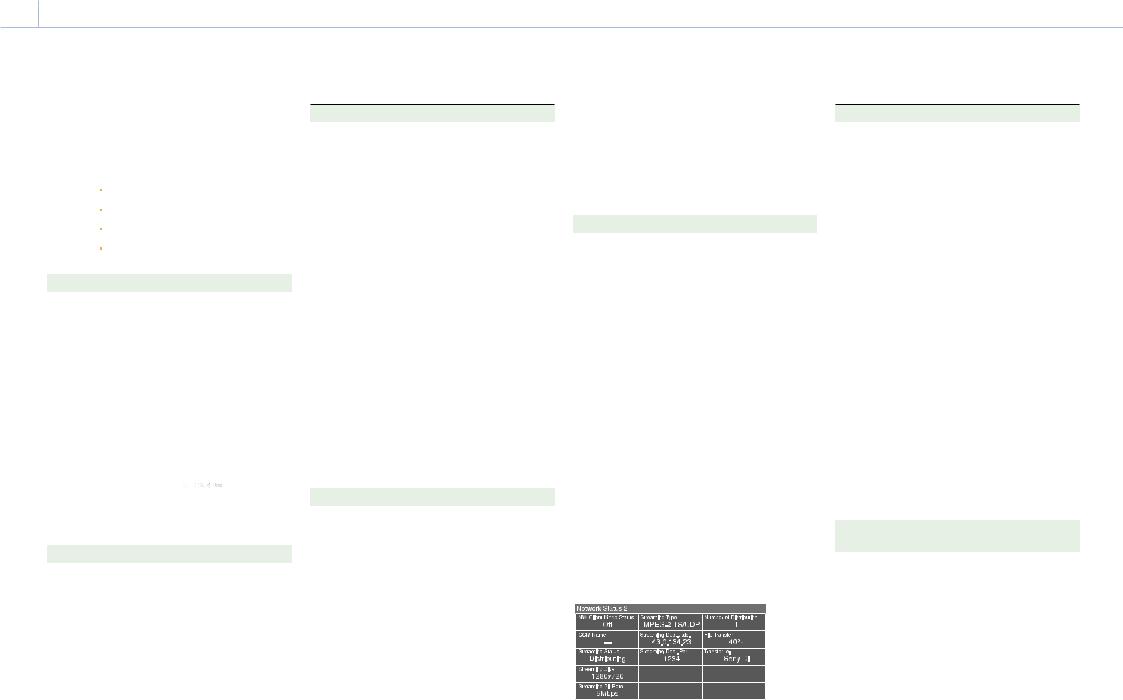
Network Status 1 screen
The Network Status 1 screen displays settings and status information related to the network.
|
|
|
|
|
|
|
|
|
|
|
|
|
Display item |
Description |
|
|
Setting |
Network setting status |
|
|
Wireless |
Wireless network setting status |
|
|
Network |
|
|
|
|
|
|
|
Device Name |
Name of device attached to the |
|
|
|
USB wireless LAN module |
|
|
|
connector |
|
|
IP Address |
IP address of wireless LAN |
|
|
(Wireless) |
connection |
|
|
|
|
|
|
MAC Addr. |
MAC address of device attached |
|
|
(Wireless) |
the USB wireless LAN module |
|
|
|
connector |
|
|
Wired LAN |
Wired LAN network connection |
|
|
|
status |
|
|
Wired LAN |
Remote control enabled/disabled |
|
|
Remote |
state when connected using a |
|
|
|
LAN cable |
|
|
IP Address |
IP address of wired LAN |
|
|
(Wired) |
connection |
|
Network Status 2 screen
The Network Status 2 screen displays settings and status information related to streaming.
Display item |
Description |
|
NW Client |
Network client mode status |
|
Mode Status |
For details about the status, see |
|
|
“Network client mode status” |
|
|
(page 14). |
|
CCM Name |
Name of the connected CCM |
|
|
when using network client mode |
|
Streaming |
Streaming distribution status |
|
Status |
|
|
|
|
|
Streaming Size |
Picture size of the currently |
|
|
selected streaming setting |
|
|
|
|
Streaming Bit |
Bit rate of the currently selected |
|
Rate |
streaming setting |
|
Streaming Type Type of the currently selected |
||
|
streaming setting |
|
Streaming |
Streaming destination address |
|
Dest. Add. |
|
|
Streaming |
Streaming destination port |
|
Dest. Port |
|
|
Number of |
Number of streaming distribution |
|
Distribution |
destinations |
|
File Transfer |
File transfer progress status |
|
|
|
|
Transfer to: |
Server name of file transfer |
|
|
destination |
|
Network client mode status |
||
|
|
|
Status |
State |
Description |
display |
|
|
Off |
CCM not |
Network client mode is |
|
connected |
off. |
|
|
|
Connected |
CCM |
Network client mode is |
|
connected |
on, CCM is connected, |
|
|
and CCM control is |
|
|
enabled. |

00015 1. Overview: Screen Display
Status |
State |
Description |
display |
|
|
Connecting |
Connecting to |
Attempting to connect |
|
CCM |
to CCM (or |
|
(disconnected) |
disconnecting). Wait |
|
|
until connection |
|
|
(disconnection) is |
|
|
successful. If the status |
|
|
does not change from |
|
|
“Connecting,” the CCM |
|
|
address setting may be |
|
|
incorrect. Check that the |
|
|
address is set correctly. |
Awaiting |
CCM |
Network client mode is |
|
connection |
on, but the network |
|
standby |
setting is off. Enable the |
|
|
network setting to |
|
|
connect to the CCM. |
Address |
CCM |
The host name or IP |
Error |
address |
address of the CCM to |
|
error |
connect may be |
|
|
incorrect. Check that the |
|
|
setting is correct. |
Auth. Failed |
CCM user |
The user name or |
|
name/ |
password used to |
|
password |
connect to the CCM |
|
error |
may be incorrect. Check |
|
|
that the setting is |
|
|
correct. |
No Inet |
Internet |
Cannot connect to the |
Access |
connection |
network. The network |
|
error |
settings may be |
|
|
incorrect. Check the |
|
|
network settings. |
Cert. not |
CCM |
The CCM certificate is |
Valid |
certification |
not valid. The date |
|
not valid |
setting may be invalid. |
|
error |
Check the date setting. |
|
|
|
Assignable Button Status screen
Battery Status screen
Displays the status of the battery attached to the camcorder.
|
|
|
|
|
|
|
|
|
|
|
|
|
Display item |
Description |
|
|
Detected |
Detected type of the battery |
|
|
Battery |
|
|
|
|
|
|
|
Remaining |
Remaining capacity (%) |
|
|
Charge Count |
Number of recharges |
|
|
Capacity |
Remaining capacity (Ah) |
|
|
Voltage |
Voltage |
|
|
Manufacture |
Date of battery manufacture |
|
|
Date |
|
|
|
Power Source |
Power supply source |
|
|
Supplied |
Supplied power source voltage |
|
|
Voltage |
|
|
Media Status screen
Displays the status of the recording media.
|
|
|
|
|
|
|
|
|
|
|
|
|
|
|
|
|
|
|
|
|
|
|
|
|
|
|
|
|
|
|
|
|
|
|
|
|
|
|
|
|
|
|
|
|
|
|
|
|
|
|
|
|
|
|
|
|
|
|
|
|
|
|
|
Display item |
Description |
||||
|
SxSA |
Remaining capacity (bar graph |
||||
|
|
|
|
and remaining time display) and |
||
|
|
|
|
media life of media in slot A |
||
|
SxSB |
Remaining capacity (bar graph |
||||
|
|
|
|
and remaining time display) and |
||
|
|
|
|
media life of media in slot B |
||
|
SD Proxy |
Remaining capacity (bar graph |
||||
|
|
|
|
and remaining time display) and |
||
|
|
|
|
media life (displayed only if |
||
|
|
|
|
available) of media in PROXY SD |
||
|
|
|
|
card slot |
||
|
SD Utility |
Remaining capacity (bar graph |
||||
|
|
|
|
and remaining capacity) and |
||
|
|
|
|
media life (displayed only if |
||
|
|
|
|
available) of media in UTILITY SD |
||
|
|
|
|
card slot |
||
A  mark is displayed if the media is protected.
Displays the names of functions assigned to assignable switches.
00016 1. Overview: Screen Display
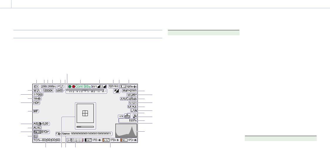
Viewfinder Screen
The viewfinder screen displays images during |
using the DISPLAY switch. |
shooting (recording or recording standby) |
The information to display is linked to the settings |
and playback with camcorder information |
in Operation >Super Impose in the setup menu, |
superimposed on the display. |
and the settings of the corresponding switches. |
You can toggle the display of information on/off |
|
|
1 |
23 4 |
5 67 |
8 |
9 |
10 11 |
12 |
|
|
36 |
37 |
|
|
|
|
|
|
13 |
14 |
34 |
35 |
|
|
|
|
|
|
15 |
16 |
|
33 |
|
|
|
|
|
|
17 |
18 |
|
|
|
|
|
|
|
|
19 |
20 |
32 31 |
|
|
|
|
Proxy |
21 |
22 |
||
|
|
|
|
|
|
||||
|
|
|
|
|
|
23 |
|
||
30 29 |
|
|
|
|
|
|
|
||
|
|
|
|
|
|
|
|
||
|
|
28 |
27 26 |
25 |
|
24 |
|
|
|
1. Extender indicator
“EX” appears when the lens extender function is ON.
2.Zoom position indicator (with lens mounted)
Displays the zoom position of the zoom lens in the range 0 to 99.
3.Color temperature indicator
Displays the color temperature of the white balance.
4. Focus position indicator (with lens mounted)
Displays the focus position as a distance to the subject (unit: meters).
5.Iris position indicator (with lens mounted)
Displays the iris position setting.
6.Electric color temperature filter indicator
Appears when the CC5600K function is on.
7.Depth of field indicator (serial lens mounted)
Displays the depth of field using a bar. The units for display are set using Operation >Display On/Off >Lens Info in the setup menu, and can be set to meters or feet.
8.Recording mode indicator
Displays the following recording operation states of the camcorder.
Indicator |
Meaning |
Rec |
During recording |
Stby |
Recording standby |
Cont Rec |
Clip continuous recording in |
|
progress |
Cont Stby |
Recording standby in clip continuous |
|
recording mode |
S&Q Rec |
Recording in progress in Slow & |
|
Quick Motion mode |
S&Q Stby |
Recording standby in Slow & Quick |
|
Motion mode |
Rec |
Recording in Picture Cache Rec |
|
mode |
Cache |
Recording standby in Picture Cache |
|
Rec mode |
Int Rec |
Recording in progress in Interval Rec |
|
mode |
Int Stby |
Recording standby in Interval Rec |
|
mode |
Int Stby |
Recording paused in Interval Rec |
|
mode (during pause intervals) |
Sml Rec |
Recording in progress in Simul Rec |
|
mode |
Sml Stby |
Recording standby in Simul Rec |
|
mode |
CALL |
Call received from external |
|
connected device |
Green tally is displayed when the camcorder is in the following states.
ˎˎMaintenance >Camera Config >HD-SDI Remote I/F is set to Green Tally in the setup menu and a recording control signal is output from the SDI OUT connector.
ˎˎGreen tally signal received (when a camera adaptor is mounted on the camcorder and a camera extension unit is connected)
9. Wireless receiver function indicator
Displays “W” when a slot-in receiver is attached to the camcorder, and displays the reception level for each channel that can be used by the receiver (1ch, 2ch, or 4ch).
Normal: Displays the strength of the received signal level by the number of white segment indicators.
Analog receiver muting/Digital receiver error rate warning: Displays the strength of the received signal level by the number of gray segment indicators.
If the received level exceeds the peak: Displays “P” in place of the indicator.1)
If the transmitter is in power-save mode: “S” is displayed.
Receiver battery is low: The corresponding channel number and indicators flash.1)
1) When using the DWR-S02D
10. S&Q Motion (Slow & Quick) frame rate indicator
Displays the shooting frame rate when the camcorder is set to Slow & Quick Motion recording mode.
11.GPS indicator (page 57)
12.Battery capacity/voltage display
Displays the following indicators according to the type of battery power source.
Battery type |
Indicator |
Info battery |
Battery remaining capacity |
|
icon and remaining recording |
|
time |
Anton/Bauer |
Remaining battery capacity (% |
battery |
indicator) |
Other batteries |
Input voltage |
13.Recording format (picture size) indicator
Displays the picture size of clips recorded onto SxS memory cards.
14.Recording format (system frequency and scan method) indicator
Displays the currently configured camcorder system frequency and the recording format scan method.
00017 1. Overview: Screen Display
15.Recording format (codec) indicator / 1-slot Simul Rec indicator
Displays the format name of clips recorded onto SxS memory cards.
“/Sub” is displayed in 1-slot Simul Rec mode (page 51).
16. Gamma indicator
Display the gamma setting.
|
Menu settings |
|
Indicator |
|
Operation |
Paint >Gamma setting |
|
|
|
>Display |
Gamma |
Gamma |
Gamma |
|
On/Off |
|
Category |
Select |
|
>Gamma |
|
|
|
|
Off |
– |
– |
– |
– |
On |
Off |
– |
– |
Gamma |
|
|
|
|
Off |
|
On |
STD |
STD1 DVW |
STD1 |
|
|
|
|
|
|
|
|
STD2 x4.5 |
STD2 |
|
|
|
|
|
|
|
|
STD3 x3.5 |
STD3 |
|
|
|
|
|
|
|
|
STD4 240M |
STD4 |
|
|
|
|
|
|
|
|
STD5 R709 |
STD5 |
|
|
|
|
|
|
|
|
STD6 x5.0 |
STD6 |
|
|
|
|
|
|
|
HG |
HG1 |
HG1 |
|
|
|
3250G36 |
|
|
|
|
|
|
|
|
|
HG2 |
HG2 |
|
|
|
4600G30 |
|
|
|
|
HG3 |
HG3 |
|
|
|
3259G40 |
|
|
|
|
HG4 |
HG4 |
|
|
|
4609G33 |
|
|
|
|
|
|
On |
On |
User |
User 1 |
User 1 |
|
|
|
User 2 |
User 2 |
|
|
|
|
|
|
|
|
User 3 |
User 3 |
|
|
|
User 4 |
User 4 |
|
|
|
User 5 |
User 5 |
|
|
|
|
|
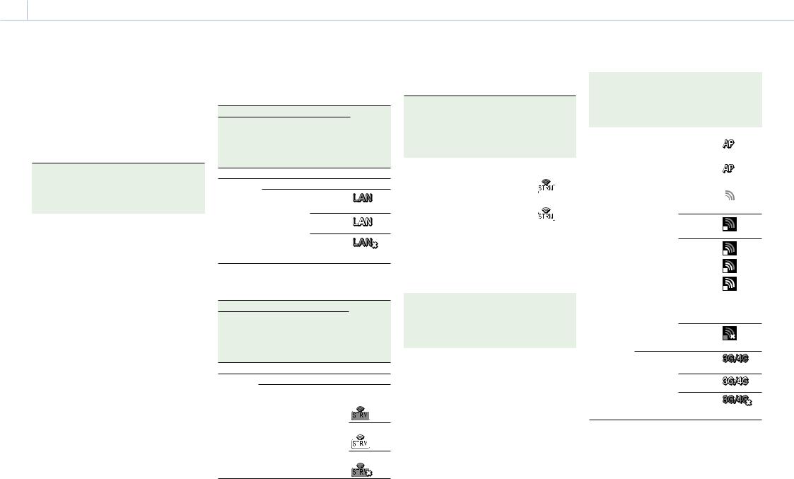
17. Timecode external lock indicator
Displays timecode lock when the timecode is input from an external source.
18. Wired LAN connection status
Displays the wired LAN network setting and connection status using icons.
|
State |
|
Icon |
Operation |
Maintenance |
Network |
|
>Display On/ |
>Network |
connection |
|
Off >Network |
>Wired LAN |
status |
|
Condition |
|
|
|
Off |
– |
– |
– |
On |
Disable |
– |
– |
|
Enable |
Connecting |
|
|
|
to LAN |
(flashing) |
|
|
|
|
|
|
Connected |
|
|
|
to LAN |
|
|
|
LAN |
|
|
|
connection |
|
|
|
error |
|
19. Streaming indicator
Displays the status of streaming using icons.
|
State |
|
Streaming |
Operation |
Maintenance |
Maintenance |
state/Icon |
>Display On/ |
>Streaming |
>Network |
|
Off |
>Setting |
Client Mode |
|
>Streaming |
|
>Setting |
|
Status |
|
|
|
Off |
– |
– |
– |
On |
Off |
Off |
– |
|
On |
Off |
Not |
|
|
|
streaming |
|
|
|
Streaming |
|
|
|
Error |
The following icons are displayed when streaming from a CCM.
|
State |
|
|
|
Streaming |
|
Operation |
Maintenance |
Maintenance |
|
state/Icon |
||
>Display On/ |
>Streaming |
>Network |
|
|
|
|
Off |
>Setting |
Client Mode |
|
|
|
|
>Streaming |
|
>Setting |
|
|
|
|
Status |
|
|
|
|
|
|
|
|
|
|
|
|
|
On |
Off |
On |
|
Not |
||
|
|
|
|
|
streaming |
|
|
|
|
|
|
|
|
|
|
|
|
|
|
|
|
|
|
|
|
|
|
|
|
|
|
|
Streaming |
|
|
|
|
|
|
|
|
|
|
|
|
|
|
|
|
|
|
|
|
|
|
[Note]
Icons are not displayed before streaming starts.
20. Wireless network status indicator
Displays the network setting and connection status using icons.
|
State |
|
Icon |
Operation |
Maintenance |
Network |
|
>Display On/ |
>Network |
connection |
|
Off >Network |
>Wireless |
status |
|
Condition |
Network |
|
|
|
|
|
|
Off |
– |
– |
– |
|
State |
|
|
Icon |
|||
Operation |
Maintenance |
Network |
|
|
|
|
|
>Display On/ |
>Network |
connection |
|||||
Off >Network |
>Wireless |
status |
|
|
|
|
|
Condition |
Network |
|
|
|
|
|
|
|
|
|
|
|
|
|
|
On |
Off |
– |
|
|
– |
||
|
Wi-Fi Access |
Connecting |
|||||
|
Point |
using Wi-Fi |
1) |
|
(flashing) |
||
|
|
|
|
|
|||
|
|
|
|
|
|
||
|
|
Wi-Fi standby |
|||||
|
|
(connected) |
|||||
|
|
|
|
|
|
||
|
Wi-Fi Station |
Connecting |
|
|
|
||
|
|
|
|||||
|
|
using Wi-Fi |
|
|
|
|
|
|
|
|
|
|
|
|
|
(flashing)
Access point search
Access point connection
|
|
Icon varies |
|
|
with signal |
|
|
strength. |
|
Access point |
|
|
connection |
|
|
error 1) |
|
Modem |
Connecting |
|
|
using 3G/4G |
(flashing) |
|
|
|
|
Connected |
|
|
using 3G/4G |
|
|
3G/4G |
|
|
connection |
|
|
error 1) |
|
1)This icon is displayed in the following cases.
ˎˎWhen a device is not attached
ˎˎWhen a device is attached with different settings
21. Proxy indicator
Displays “Proxy” when proxy recording is on (Operation >XAVC Proxy Rec Mode >Setting in the setup menu is set to On). During setup, “Proxy” blinks. “Proxy Rec” is displayed during proxy recording.

00018 1. Overview: Screen Display
Displays  and transfer rate (%) during proxy file transfer. When transfer finishes,
  disappears to indicate 100% transfer.
22. Network client mode indicator
Displays the status of the connection to the CCM (Network RX Station configured as Connection Control Manager) using icons when network client mode is on.
|
State |
|
Icon |
Operation |
Maintenance |
State |
|
>Display On/ |
>Network |
|
|
Off >NW |
Client Mode |
|
|
Client Mode |
>Setting |
|
|
Status |
|
|
|
Off |
– |
– |
– |
On |
Off |
– |
– |
|
On |
CCM |
|
|
|
connected |
|
|
|
Connecting to |
|
|
|
CCM |
(flashing) |
|
|
(disconnected) |
|
|
|
|
|
|
|
CCM |
– |
|
|
connection |
|
|
|
standby |
|
|
|
CCM |
|
|
|
connection |
|
|
|
error |
For details |
|
|
|
about errors, |
|
|
|
see |
|
|
|
(page 14). |
23. Video signal indicator
Displays the video signal in realtime as a waveform, vectorscope, or histogram.
24.Recording media state/remaining capacity indicator for each media slot
Displays the state and remaining capacity of the media in SxS slot A, SxS slot B, and the PROXY SD card slot.
SxS slot icon indicator
*SxS slot A (SxSA) example. The icons for SxS slot B are labeled SxSB.
Icon |
Media state |
–Media not inserted or not mounted
Media mounted
 Media mounting (flashing)
Recording (active)
(orange bar)
Playback (active)
(green
indicator)
Recording/playback (active)
(orange bar + green indicator)
SD card (for proxy data recording) icon indicator
Icon |
Media state |
–Media not inserted or not mounted
Media mounted
 Media mounting (flashing)
Recording (active)
(orange bar)
The remaining recording time is displayed numerically.
25. Audio level meter indicators
Displays the levels of audio channels 1 and 2.
26. Clip name display
Displays the name of the clip currently recording when recording, or displays the name of the next clip to be recorded during recording standby.
27. Focus assist indicator
Displays a detection frame (focus area marker) indicating the area for detection of degree of
focus, and a level bar (focus assist indicator) indicating the degree of focus within that area.
28. Time data display
Displays the remaining recording/playback time, timecode, user bits, etc., as selected by the DISPLAY switch (page 8).
29.SD card indicator for saving configuration data
Displays the state of the SD card (for saving configuration data) inserted in the UTILITY SD card slot.
Icon |
Media state |
–SD card not inserted or not mounted
SD card mounted
Mounted SD card is protected
SD card mounting
(flashing)
30. SDI output REC trigger indicator
Displays the superimposition state of the recording command sent to the SDI connector output.
It is displayed when Maintenance >Camera Config >HD SDI Remote I/F is set to “Characters” in the setup menu.
31. ALAC indicator
Displays “ALAC” when the ALAC (Auto Lens Aberration Correction) function is set to be performed automatically.
ALAC will be performed automatically when an ALAC-compatible lens is attached, the ALAC function is enabled, and Maintenance >Camera
Config >ALAC is set to “Auto” in the setup menu.
32. AE (auto iris) mode indicator
Displays the current operating mode of the auto iris function using an icon and auto iris override level.
Icon Meaning
Backlight mode
Standard mode
Spotlight mode
33.Auto focus mode indicator (when an auto focus lens is attached only)
Displays the focus adjustment mode of the camcorder.
ˎˎAF (auto focus) ˎˎMF (manual focus)
ˎˎMF* (manual focus with MF assist function on) ˎˎFull MF (full manual focus)
34. ND filter indicator
Displays the position number of the currently selected ND filter (page 5).
When “Electrical CC” is assigned to an assignable switch, the position (A/B/C/D) of the electrical CC filter is displayed on the right of the ND filter indicator (1 to 4).
35. Gain indicator
Displays the gain setting (dB), set using the GAIN switch, of the video amplifier.
36.Shutter mode/shutter speed indicator/Flash Band Reduce status indicator
Displays the shutter mode or shutter speed.
“Setting the Electronic Shutter” (page 40)
If Flash Band Reduce (page 100) is set to On in the Operation menu, FBR is displayed when the shutter is in a non-operating state.
37. White balance mode indicator
Displays the currently selected white balance automatic adjustment memory.
ATW: ATW (Auto Tracing White Balance) mode W:A: Memory A mode
W:B: Memory B mode W:C: Memory C mode W:P: Preset mode

00019 1. Overview: Screen Display
3200K: Appears when an assignable switch assigned with Color Temp SW 3200K is on
4300K: Appears when an assignable switch assigned with Color Temp SW 4300K is on
5600K: Appears when an assignable switch assigned with Color Temp SW 5600K is on
6300K: Appears when an assignable switch assigned with Color Temp SW 6300K is on

0002 2. Preparation
Preparing a Power Supply
For safety, use only the Sony battery packs and AC adaptors listed below.
ˎˎBP-FLX75 Lithium-ion Battery Pack
[CAUTION]
Danger of explosion if battery is incorrectly replaced. Replace only with the same or equivalent type recommended by the manufacturer.
When you dispose of the battery, you must obey the law in the relative area or country.
For details on the battery charging procedure, refer to the battery charger operation manual.
Note on using the battery pack
A warm battery pack may not be able to be fully recharged.
Using a Battery Pack
Press the battery pack against the back of the camcorder, aligning the line on the side of the battery pack with the line on the camcorder. Then slide the battery pack down until its “LOCK” arrow aligns with the line on the camcorder.
To detach the battery pack, pull the battery pack up by holding the release button in.
[Notes]
ˎˎIf the battery pack is not attached correctly, the terminals may become damaged.
ˎˎDuring recording and playback (while the ACCESS lamp on the right-side panel is lit in blue and the ACCESS lamp in the card slot section is lit in orange), be careful never to remove the battery pack.
Doing so may corrupt the data recorded on the card.
ˎˎMake sure to power the camcorder off before replacing the battery pack.
When a BP-FLX75 Battery Pack is used, the camcorder will operate continuously for approximately 150 minutes.
[WARNING]
Batteries shall not be exposed to excessive heat such as sunshine, fire or the like.
[Note]
The battery pack operating time depends on the frequency of use of the battery pack, and the ambient temperature when used.
Using AC Power
Mount an AC-DN2B/DN10 on the camcorder in the same way as a battery pack, then connect to the AC power supply.
Before use, charge the battery pack with a charger suitable for each battery.

00021 2. Preparation
Attaching a Viewfinder
[CAUTION]
When the viewfinder is attached, do not leave the camcorder with the eyepiece lens facing the sun.
Direct sunlight can enter through the lens, be focused in the viewfinder and cause fire.
A viewfinder is available separately.
This section describes attachment of the CBK-VF02 as an example.
For procedures for attaching other viewfinders, refer to a manual supplied with each viewfinder.
Attaching a Viewfinder
[Note]
When attaching a viewfinder, take note of the following points.
ˎˎBe sure to the power off the camcorder before coupling the viewfinder connector to the camcorder’s VF connector (26-pin). If you make this connection when the camcorder power is on, the viewfinder may not function properly.
ˎˎCouple the viewfinder connector firmly to the camcorder’s VF connector (26-pin). If the coupling is loose, noise may appear on the video or the tally light may not operate properly.
1 [1] Loosen the viewfinder left-to-right positioning ring, [2] attach the viewfinder to the viewfinder fitting shoe, and [3] tighten the viewfinder left-to-right positioning ring.
Slide stopper


 [3]
[3]
[2] [1]


Left-to-right positioning 
 ring
ring 

2 Couple the viewfinder connector to the VF connector (26-pin).
VF connector (26-pin)
 Up
Up
You can detach the viewfinder by following the attaching procedure in reverse order. But, when detaching the viewfinder from the attachment shoe, pull up the stopper.
Adjusting the Diopter
Turn the diopter adjustment ring until the viewfinder image is sharpest.
Diopter adjustment ring
You can also attach a commercially available protection filter, close-up lens, etc. that is 52 mm in diameter.
the way so that your right leg does not hit the viewfinder while you are carrying the camcorder.
1 Loosen the front-to-back viewfinder positioning levers and the front-to-back viewfinder positioning knobs, and then pull the viewfinder slide assembly forward.
Adjusting the Screen
Adjust the brightness, contrast, and peaking of the viewfinder screen with the controls shown below. Outlines: Adjust using the PEAKING knob.
Contrast: Adjust using the CONTRAST knob. Brightness: Adjust using the BRIGHT knob.
2 Using a 2.5 mm diameter hexagonal wrench, detach the viewfinder slide assembly.
Hex socket bolts
Viewfinder slide assembly
Attaching the BKW-401 Viewfinder |
3 Attach the BKW-401 with the supplied bolts. |
Rotation Bracket |
|
By fitting an optional BKW-401 Viewfinder Rotation |
|
Bracket, you can rotate the viewfinder out of |
|

00022 2. Preparation: Attaching a Viewfinder
Bolts supplied with the BKW-401
4 Adjust the front-to-back position so that the arm of the BKW-401 does not touch the handle when it is raised.
Adjust position so that arm does not touch handle

00023 2. Preparation
Using the Camcorder for the First Time
When using the camcorder for the first time, configure the following settings in the menu.
For details about menu operations, see “Basic Setup Menu Operations” (page 88).
Setting the Time Zone
Set the time zone for the region of use. The default value is “UTC Greenwich.”
1 Select Operation >Time Zone >Time Zone in the setup menu.
3 Turn the MENU knob to set the year, month, or day, and then press the knob.
4 Repeat steps 2 and 3 to set the remaining digits.
5 Press the SET button.
The internal clock is set to the date set in steps 2 to 4.
Next, set the time.
6 Select Maintenance >Clock Set >Time in the setup menu.
The Time screen appears.
2 Select the time zone to use.
Setting the Date and Time of the
Internal Clock
Set the year, month, day, and day-of-week of the internal clock.
1 Select Maintenance >Clock Set >Date in the setup menu.
The Date screen appears.
2 Turn the MENU knob to select the year, month, or day, and then press the knob.
The selected year, month, or day becomes editable.
7 Set the time in the same way as when setting the date.
8 Press the SET button.
The time is registered in the internal clock.
To cancel the setting, press the Cancel button.
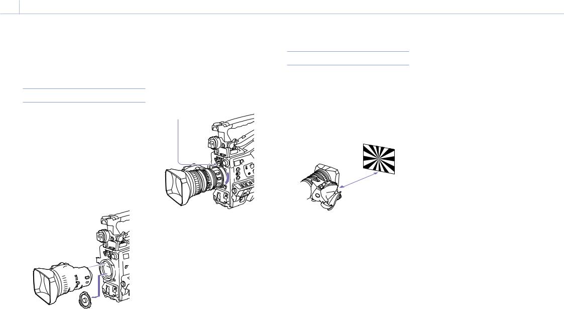
00024 2. Preparation
Mounting and Adjusting the Lens
[Note]
When connecting or disconnecting the lens cable to this connector, power off the camcorder first.
Attaching a Lens
The lens is available separately.
This section describes an example lens attachment.
For information about using the lens, refer to the operation manual for the lens.
1 Push the lens locking lever up and remove the lens mount cap from the lens mount.
2 Align the center pin on the lens with the center slot in the lens mount, and insert the lens into the mount.
[CAUTION]
If the lens is not firmly locked, it may come off while the camcorder is being used. This could cause a serious accident. Make sure the lens is firmly locked. It is recommended that the lens mount securing rubber be put on the lens locking lever as illustrated below.
Lens mount securing rubber
3 |
Adjusting the Flange Focal Length
If the lens does not stay in focus properly as you zoom from telephoto to wide angle, adjust the flange focal length (the distance from the plane of the lens mounting flange to the imaging plane, also called flange-back).
Make this adjustment just one time after mounting or changing the lens.
When carrying out the adjustment, use a flange focal length adjustment chart as the subject.
Approx. 3 m (10 ft.)
5 Use manual or power zoom to set the lens to telephoto.
6 Point the camcorder at the chart by turning the focus ring and focus on it.
7 Set the zoom ring to wide angle.
8 Turn the F.f or F.B ring until the chart is in focus, being careful not to disturb the focus ring.
9 Repeat steps 5 to 8 until the chart stays in focus all the way from wide angle to telephoto.
10 Tighten the F.f or F.B ring fixing screws.
2 


 1
1
1
3 Holding the lens in place, push the lens locking lever down to lock the lens.
4 Connect the lens cable to the LENS connector.
5 Secure the lens cable with the cable clamp.
If an aberration correction lens is attached
The aberration correction function is activated automatically. 1) Starting the camcorder with an aberration correction lens may require more time than normal because of data loading at start-up. Contact a Sony service representative for information about aberration correction lenses.
1)The aberration correction function does not operate if Maintenance >Camera Config >ALAC in the setup menu is set to Off.
[Notes]
ˎˎIf you use a subject with insufficient contrast, or move the camcorder or subject during adjustment, this will cause an adjustment error.
ˎˎPlace the subject (the flange focal length adjustment chart) so that it appears at the center of the screen at the telephoto end. Arrange it so that no nearby object (no object closer to the camera than the chart) enters the screen at the wide-angle end.
1 Set the iris to manual.
2 Place the supplied flange focal length adjustment chart about 3 m (10 ft) in front of the camera.
3 Open the iris.
The depth-of-field is reduced when the iris is open, making adjustment easier.
4 Loosen the fixing screws on the F.f or F.B ring (flange focal length adjustment ring).
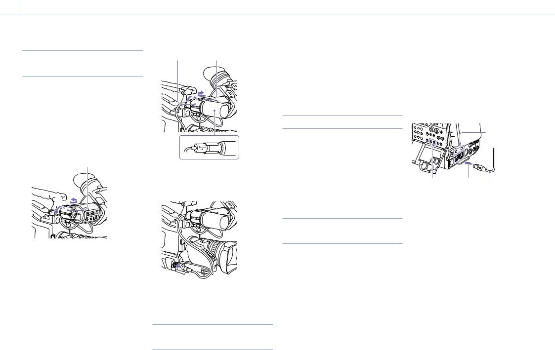
00025 2. Preparation
Preparing the Audio Input System
Connecting a Microphone to the MIC IN Connector
You can attach a stereo microphone (available separately) to the microphone holder of the viewfinder (available separately).
This section describes an example microphone attachment.
For procedures for attaching a microphone holder to other viewfinders, refer to the manual supplied with each viewfinder.
1 Loosen the screw and open the microphone holder clamp.
Microphone holder clamp

 [1]
[1]


 [2]
[2] 
2 Place the microphone in the microphone holder.
[1]Place the microphone in the holder so that “UP” is at the top.
[2]Close the microphone holder.
[3]Tighten the screw.
[2][3]
[1]
3 Plug the microphone cable into the MIC IN connector, then set the AUDIO IN switch for the channel on which you want to record the audio from this microphone to FRONT.
4 Secure the microphone cable with the cable clamp.
Connecting Microphones to the AUDIO IN Connectors
You can connect up to two monaural microphones to the AUDIO IN CH-1/CH-2
connectors, using an optional CAC-12 Microphone Holder.
Supported microphones: ECM-674/678 electret condenser microphone
For details about attaching the microphone holder and microphone, refer to the instruction manual of each product.
Attaching a Wireless Receiver
To use a Sony wireless microphone system, power the camcorder off and then attach a wireless receiver.
ˎˎDWR-S02D Digital Wireless Receiver ˎˎWRR-855S, URX-S03D UHF Synthesized Tuner
Unit
For details about attaching a wireless receiver, refer to the instruction manual of each product.
Connecting Line Input Audio
Equipment
1 Connect the audio output connector of the audio equipment that supplies the line input signal to the AUDIO IN CH-1 or CH-2 connector.
2 Set the AUDIO IN selector for the channel to which the audio signal source is connected to LINE.
XLR connection automatic detect function
ˎˎWith the XLR connection automatic detection function switched off (the factory default setting): Set the AUDIO IN CH1/CH2 switch to REAR for the channels to which the audio equipment is connected.
ˎˎWith the XLR connection automatic detection function switched on: When a cable is connected to the AUDIO IN CH-1 or CH-2 connector, the input from that connector is automatically selected for audio recording, regardless of the setting of the AUDIO IN CH1/ CH2 switch.
The XLR connection automatic detection function can be switched on/off using Maintenance >Audio >Rear XLR Auto in the setup menu.
[4]
[1] |
[2] |
[3] |
[1]AUDIO IN CH1/CH2 switches
[2]To AUDIO IN CH-1 or CH-2 connector
[3]Monaural microphone
[4]AUDIO IN selector switches
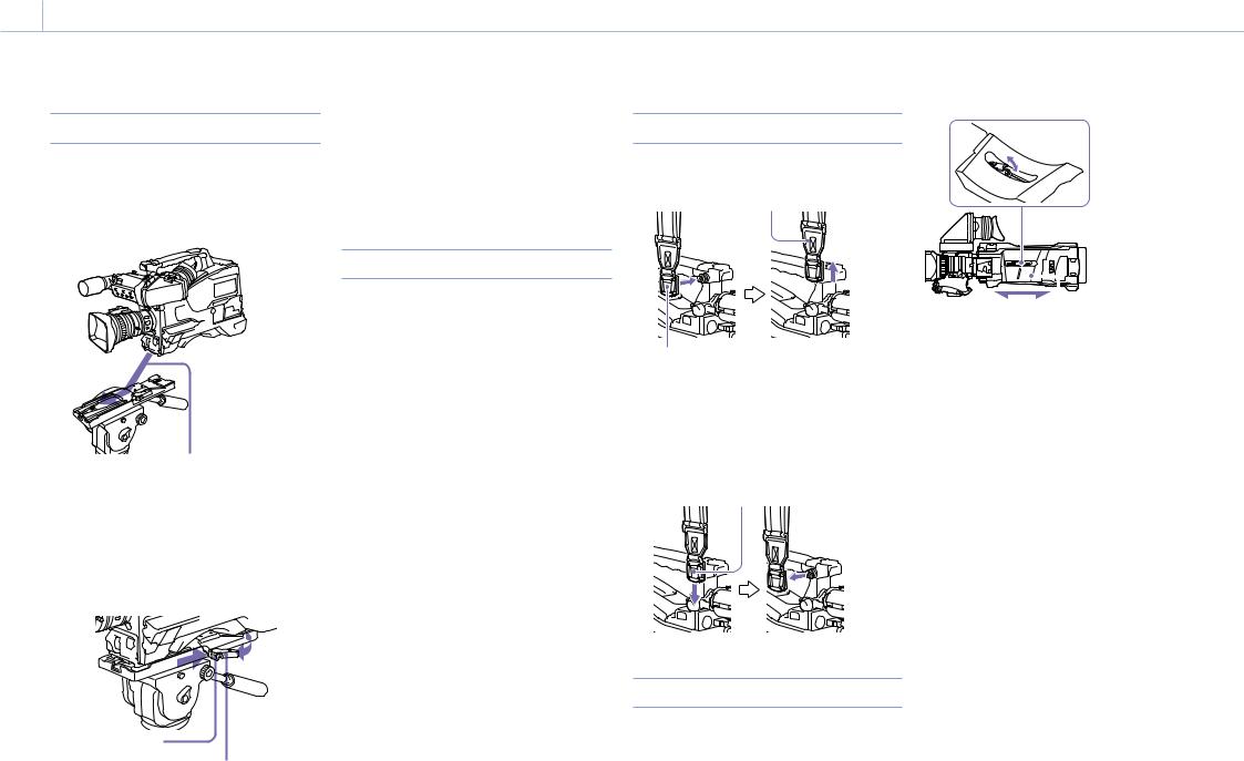
00026 2. Preparation
Attaching and Adjusting Peripheral Devices
Mounting on a Tripod
1 Attach the optional VCT-14/U14 Tripod Adaptor to the tripod.
2 Mount the camcorder on the tripod adaptor.
Slide the camcorder forward along the groove in the adaptor until it clicks.
3 Make sure that the camcorder is securely attached by moving it back and forth.
To remove the camcorder from the tripod attachment, hold down the red button and pull the lever in the direction of the arrow.
Red button
Lever
[Note]
The tripod adaptor pin may remain in the engaged position even after the camcorder is removed. If this happens, press the red button and move the lever as shown above until the pin returns to the stowed position. If the pin remains
in the engaged position, you will not be able to mount the camcorder on the tripod adaptor.
Connecting a Video Light
With this camcorder, you can use the Anton Bauer Ultralight 2 or equivalent video light (powered by 12 V with maximum power consumption of 50 W). ˎˎIf you connect the video light to the LIGHT
connector on the camcorder and set the LIGHT switch to AUTO, you can turn the light on and off automatically as you start and stop recording on this camcorder.
ˎˎThe output of the LIGHT connector on the camcorder is regulated to 12 V even when the camcorder is supplied with over 12 V power (through the DC IN connector or battery pack). The brightness or color temperature of the light will not change in response to voltage increase.
[Notes]
ˎˎDo not connect video lights with power consumption of 50 W or greater.
ˎˎThe brightness or color temperature of the light will change when the voltage (supplied through the DC IN connector or from the battery pack) is less than 12 V.
Attaching the Shoulder Strap
1 Fit one of the clips to a shoulder strap fitting.
Pull up the strap to lock the fitting.
Clip
2 Fit the other clip to the shoulder strap fitting on the other side of the grip in the same way.
To remove the shoulder strap, refer to the following diagram.
Press here and pull in the direction shown by the arrow to release.
To attach a video light, fit the video light to the accessory shoe on the camcorder grip, and connect the video light cable to the LIGHT connector.
[Note]
The accessory shoe on the camcorder is of the 1/4-inch tapped hole type. If you want to replace this with a slide-type shoe, use the supplied cold shoe kit.
Adjusting the Shoulder Pad Position
You can slide the shoulder pad back and forth within a 40 mm range. This adjustment helps you get the best balance for shooting with the camcorder on your shoulder.
1,3
2 
Shoulder pad
1 Raise the lever in the center of the shoulder pad to unlock the shoulder pad.
2 Slide the shoulder pad backward or forward until it is in the most convenient position.
3 Bring down the lever to lock the shoulder pad in the selected position.
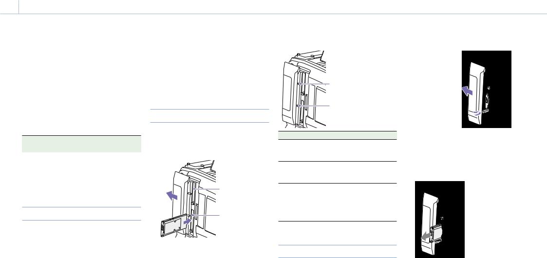
00027 2. Preparation
Handling SxS Memory Cards
This camcorder records video and audio on SxS memory cards (not supplied) loaded into one or both of its memory card slots.
In addition to SxS memory cards, you can also use XQD memory cards (not supplied) with the QDA EX1 XQD ExpressCard Adaptor (optional) or SDXC/SDHC cards (not supplied) with the MEADSD02 Media Adaptor (optional) in the camcorder to make recordings.
The file system supported by each type of media is given below.
Memory card |
File system |
|
|
|
exFAT |
UDF |
FAT |
SxS memory cards |
Yes |
Yes |
No |
XQD memory cards |
Yes |
Yes |
No |
SDXC cards |
Yes |
No |
No |
SDHC cards |
No |
No |
Yes |
About SxS Memory Cards
SxS memory cards
trademarks and trade names are the property of their respective owners.
[Note]
Use SxS PRO+ memory cards when recording in XAVC-I 3840×2160P.
Inserting SxS Memory Cards
1 Slide the cover to the left to open.
2 Insert an SxS memory card into a card slot.
Slot A
Slot B
[Note]
Use Sony SxS memory cards (SxS PRO+, SxS PRO, |
Make sure to insert the SxS card in the correct |
|
orientation. Hold the card with the arrow on one side |
||
or SxS-1) with this camcorder. |
||
facing the direction shown in the diagram, and then |
||
|
insert the card. |
SxS PRO+ series
SxS PRO series
SxS-1 series
The memory cards listed above comply with the ExpressCard memory card standard.
ˎˎSxS, SxS PRO+, SxS PRO, and SxS-1 are trademarks of Sony Corporation.
ˎˎThe ExpressCard label and logo are the property of the Personal Computer Memory Card International Association (PCMCIA) and are licensed to Sony Corporation. All other
The ACCESS indicator lights in orange, and then lights in green to indicate that the memory card is usable.
3 Close the cover.
ACCESS indicator status
Card slots A and B each have an ACCESS indicator that indicate the slot status.
|
Slot A access indicator |
|
Slot B access indicator |
Indicator |
Slot status |
Lights in |
Accessing the SxS memory card |
orange |
(lights during data reading and |
|
writing) |
Lights in |
Standby (the loaded SxS memory |
green |
card is ready for recording or |
|
playback) |
Not lit |
No SxS memory card is loaded. |
|
An unusable card is loaded. |
|
An SxS memory card is loaded, but |
|
the other slot is selected. |
Ejecting SxS Memory Cards
1 Open the cover, and then press the EJECT button to release the lock and extract the button.
Press the button once to release the lock.
2 Press the EJECT button again to eject the card.
[Note]
When you press the EJECT button, take care not to impede the SxS memory card. If the movement of the SxS memory card is impeded, the lock may fail to release.
[Note]
Data integrity cannot be guaranteed if you power the camcorder off or remove a memory card while the card is being accessed. All data recorded on the card may be discarded. Always make sure that the ACCESS indicator is lit green or not lit before you power the camcorder off or remove a memory card.

00028 2. Preparation: Handling SxS Memory Cards
Selecting the SxS Memory Card to Use
When SxS memory cards are loaded in both slot A and slot B, you can press the SLOT SELECT button to select the SxS memory card to use.
When the remaining recording time on the recording SxS memory card falls below 60 seconds, the remaining capacity indicator for the corresponding media slot flashes on the viewfinder screen to indicate that the camcorder will switch SxS memory cards soon. Subsequently, the camcorder switches
automatically to the other card when the selected card becomes full, and recording continues.
[Notes]
ˎˎThe SLOT SELECT button is disabled during playback. The memory cards are not switched even if you press the button. Button operations are enabled when a thumbnail screen (page 79) is displayed.
ˎˎIn 1-slot Simul Rec mode, recording may not be able to continue after switching cards if the next card already has 200 or more clips.
Formatting (Initializing) SxS Memory
Cards
When an unformatted SxS memory card or an SxS memory card formatted in another specification is inserted, a message notifying you that the media has a different file system appears. In this case, format the memory card in the following way. SxS memory cards are formatted in exFAT or FAT by factory default.
[Note]
SxS memory cards must be formatted on an XDCAM device that supports the exFAT or UDF file system or on this camcorder. Cards in other formats cannot be used.
1 Select Operation >Format Media in the setup menu.
2 Select Media(A) (slot A) or Media(B) (slot B).
3 Turn the MENU knob to select [Execute], then press the knob.
A confirmation screen prompting whether to format the card appears.
4 Turn the MENU knob to select [Execute] on the confirmation message screen, then press the knob.
Formatting begins.
During formatting, a message is displayed, and the ACCESS indicator is lit orange.
When formatting ends, a completion message appears. Press the MENU knob to dismiss the message.
If formatting fails
A format operation may fail because the SxS memory card is write protected, or because it is not the type of card specified for use with this camcorder.
In this case, an error message appears. Follow the instructions in the error message and exchange the card for an SxS memory card that can be used with this camcorder.
[Notes]
ˎˎFormatting a memory card erases all data, including recorded video data and setup files.
ˎˎUse the format function of this camcorder to format SxS memory cards for use on this camcorder. The formats of cards formatted on other devices are not recognized as valid formats, making it necessary to format them again on this camcorder.
Formatting while recording
Even while recording, the SxS memory card loaded in the other card slot can be formatted.
[Notes]
ˎˎFormatting is not supported during 1-slot Simul Rec, during playback, or when the thumbnail screen is displayed.
ˎˎDuring formatting, recording to an SxS memory card loaded in the other card slot cannot be started.
Checking the Remaining Recording
Time
You can check the remaining capacity of the SxS memory cards loaded in the two slots by checking the recording media remaining capacity indicator in the viewfinder.
The remaining recording time is calculated from the remaining capacity of the media in each slot and the current video format (recording bit rate), and is displayed in units of minutes.
You can check the remaining capacity on a bar graph by displaying the Media Status screen (page 15).
[Note]
A  mark appears when a memory card is write protected.
When to exchange SxS memory cards
ˎˎThe warning message “Media Near Full” appears, the WARNING indicator and the REC indication on the viewfinder screen flash, and the buzzer sounds when the total remaining recording time of the two memory cards falls to five minutes during recording.
Exchange one of the cards for media with available recording capacity.
ˎˎIf you continue recording, the message “Media Full” appears and recording stops when the total remaining recording time falls to 0.
[Note]
About up to 600 clips can be recorded on one SxS memory card.
The display of remaining recording time changes to “0” and the message “Media Full” appears when the clip limit is reached.
Restoring SxS Memory Cards
If for any reason an error should occur in a memory
card, the card must be restored before use.
When you load an SxS memory card that needs to be restored, a message appears in the viewfinder to ask whether you want to restore it.
To execute the restore, turn the MENU knob to select [Execute], and then press the knob.
The restoration starts.
During restoration, a message is displayed, and the ACCESS indicator is lit orange.
When restoration ends, a completion message appears. Press the MENU knob to dismiss the message.
If restoration fails
ˎˎWrite protected SxS memory cards and cards on which memory errors have occurred cannot be restored. A warning message appears for such cards. Follow the instructions in the message and unprotect the card or replace it with another card.
ˎˎSxS memory cards on which memory errors have occurred may become usable if they are reformatted.
ˎˎIn some cases, some clips can be restored while others cannot. The restored clips can be played normally.
ˎˎIf the message “Could not Restore Some Clips” keeps appearing after repeated attempts at restoration, it may be possible to restore the SxS memory card with the following procedure.
[1]Use the application software (page 162) to copy the required clips to another SxS memory card.
[2]Format the unusable SxS memory card on the camcorder.
[3]Copy the required clips back to the newly formatted SxS memory card.

00029 2. Preparation
Handling SD Cards for Saving Configuration Data
The following SD cards can be used for saving configuration data.
SDHC memory cards* (Speed Class: 4 to 10, nonUHS, Capacity: 4 to 32 GB)
* Referred to as “SD cards” in this manual.
Formatting (Initializing) SD Cards
SD cards must be formatted the first time they are used in the camcorder.
SD cards for use in the camcorder should be formatted using the format function of the camcorder. If a message appears when the SD card is inserted into the camcorder, format the SD card.
1 Select Operation >Format Media >SD Card (Utility) in the setup menu.
A confirmation screen prompting whether to format the card appears.
2 Turn the MENU knob to select [Execute], then press the knob.
Formatting begins.
During formatting, a message is displayed, and the ACCESS indicator is lit orange.
When formatting ends, a completion message appears. Press the MENU knob to dismiss the message.
[Note]
Formatting an SD card erases all data on the card. The card cannot be restored.
Checking the Remaining Capacity
You can check the remaining capacity on an SD card on the Media Status screen (page 15).
To use an SD card formatted on the camcorder in the slot of another device, make a backup of the card, then reformat the card in the device to be used.

0003 2. Preparation
Using a Media Adaptor
[Notes]
ˎˎFor professional applications, the use of other media will not provide the same high reliability and durability that is obtained using SxS memory cards.
ˎˎNot all memory cards are guaranteed to work with this camcorder. For compatible memory cards, contact your Sony dealer.
XQD Memory Cards
By using an optional QDA-EX1 XQD ExpressCard Adaptor, you can insert an XQD memory card into an SxS memory card slot and use it instead of an SxS memory card for recording and playback.
For details about using a QDA-EX1 XQD ExpressCard Adaptor, refer to the instruction manual supplied with the adaptor.
[Notes]
ˎˎHigh-speed playback may not be properly achieved with an XQD memory card.
ˎˎHigh frame rate recording in XAVC-I 3840×2160P and XAVC-L 3840×2160P may fail, depending on the media used, if an unsupported media error message appears.
ˎˎSlow motion recording using the Slow & Quick Motion recording function cannot be used with an XQD memory card.
Formatting (initializing)
XQD memory cards must be formatted the first time they are used in the camcorder.
XQD memory cards for use in the camcorder should be formatted using the format function of the camcorder. If a message appears when the XQD memory card is inserted into the camcorder, format the XQD memory card.
If an unformatted XQD memory card or an XQD memory card that was formatted in a different specification is inserted, a message asking for confirmation to format media or a message notifying you that the media has a different file system appears.
1 Select Operation >Format Media in the setup menu.
2 Select Media(A) (slot A) or Media(B) (slot B).
3 Turn the MENU knob to select [Execute], then press the knob.
A confirmation screen prompting whether to format the card appears.
4 Turn the MENU knob to select [Execute] on the confirmation message screen, then press the knob.
Formatting begins.
During formatting, a message is displayed, and the ACCESS indicator is lit orange.
When formatting ends, a completion message appears. Press the MENU knob to dismiss the message.
[Note]
Formatting an XQD memory card erases all data on the card, including protected video. The data cannot be restored.
Connection between the camcorder and a computer
Insert the recorded XQD memory card into a slot in the camcorder, and connect the camcorder to a computer using a USB cable.
To use a memory card formatted on the camcorder in the slot of another device
First, make a backup of the card, then reformat the card in the device to be used.
SD Cards
By using an optional MEAD-SD02 Media Adaptor, you can insert an SD card into an SxS memory card slot and use it for recording and playback.
[Note]
If an SD card and another memory card are used at the same time, the camcorder does not switch cards when the media becomes full. Instead, recording stops.
The following SD cards are supported.
SDXC memory cards (SD speed class: Class 10) 1) SDHC memory cards (SD speed class: Class 10) 2)
1)Supported if the file system is exFAT.
2)Supported if the file system is FAT.
For details about using an MEAD-SD02 Media Adaptor, refer to the instruction manual supplied with the adaptor.
[Notes]
ˎˎHigh-speed playback may not be properly achieved with an SD card.
ˎˎRecording and playback using SD cards is not supported when shooting in XAVC-I or XAVC-L 3840×2160P format.
ˎˎSlow motion recording using the Slow & Quick Motion recording function cannot be used with an SDXC card.
Formatting (initializing)
SD cards must be formatted the first time they are used in the camcorder.
SD cards for use in the camcorder should be formatted using the format function of the camcorder. If a message appears when the SD card is inserted into the camcorder, format the SD card. If an unformatted SD card or an SD card that was formatted in a different specification is inserted, a message asking for confirmation to format media or a message notifying you that the media has a different file system appears.
Format the card using the following procedure.
1 Select Operation >Format Media in the setup menu.
2 Select Media(A) (slot A) or Media(B) (slot B).
3 Turn the MENU knob to select [Execute], then press the knob.
A confirmation screen prompting whether to format the card appears.
4 Turn the MENU knob to select [Execute] on the confirmation message screen, then press the knob.
Formatting begins.
During formatting, a message is displayed, and the ACCESS indicator is lit orange.
When formatting ends, a completion message appears. Press the MENU knob to dismiss the message.
[Note]
Formatting an SD card erases all data on the card, including protected video. The data cannot be restored.
Connection between the camcorder and a computer
Insert the recorded SD card into a slot in the camcorder, and connect the camcorder to a computer using a USB cable.
To use a memory card formatted on the camcorder in the slot of another device
First, make a backup of the card, then reformat the card in the device to be used.
Loading...