


3-854-213-01 (1)
Remote Control Unit
|
__________________________________________ |
JP |
|
|
|
|
|
Operating Instructions |
__________________________________ |
GB |
|
|
|
|
|
Mode d’emploi |
________________________________________ |
FR |
|
|
|
|
|
Manual de instrucciones |
________________________________ |
ES |
|
|
|
|
|
Gebrauchsanweisung |
__________________________________ |
DE |
|

あとは、いつでも見られるところに必ず保管してください。
RM-BR300
© 2004 Sony Corporation
4 5
a
b
JP 2

|
|
|
|
................................................................................................ |
6 |
................................................. |
6 |
....................................................................... |
7 |
|
|
..................................................................................... |
10 |
VISCA RS-232C ... |
10 |
VISCA RS-422 ...... |
10 |
VISCA RS-232C |
|
.................................................................... |
11 |
VISCA RS-422 |
|
.................................................................... |
11 |
BRU-300 |
|
............................................................. |
12 |
............................. |
13 |
............................................................................ |
14 |
................ |
14 |
|
|
BRC-300 ..................................... |
15 |
|
|
........................................................... |
16 |
............................................................................................. |
17 |
................................................................ |
17 |
.................................................. |
18 |
VISCA RS-422 .. 18 |
|
................................................... |
19 |
JP
3 JP


内部の点検や修理は、お買い上げ店または ソニーのサービス窓口にご依頼ください。
JP 4 |
|
|
|
|
|
|
AC
AC
AC
 5 JP
5 JP

3
AE
VISCA RS-232C/RS-422
7
9
16
VISCA
3CCD BRC-300
EVI-D100
EVI-D70
EVI-D30
EVI-D100 EVI-D70 EVI-D30 BRC-300 BRC-300
( 0 40 )
JP 6 /

BRC-300
BRC-300 BRC300
890qaqsqd qf qg
1 |
|
|
|
|
|
|
|
|
|
|
|
|
|
|
VALUE |
LOCK |
|
|
PANEL |
|
BLACK |
PAN-TILT |
ONE PUSH |
|
|
||
2 |
|
|
|
|
|
LIGHT |
|
LIGHT |
RESET |
AWB |
|
|
MENU |
– |
+ |
|
RESET |
|
|
|
|
|
|
|
|
|
|
|
|
R |
|
PRESET |
|
|
|
POSITION |
|
|
|
|
|
|
|
|
MODE |
|
|
|
|
|
|
|
|||
|
BRIGHT |
|
|
|
|
|
|
|
|
|
|
||
|
|
|
|
|
|
|
|
|
|
|
|
||
3 |
|
|
|
SHIFT |
1 |
2 |
3 |
|
4 |
5 |
6 |
7 |
8 |
|
|
|
|
9 |
10 |
11 |
|
12 |
13 |
14 |
15 |
16 |
|
– |
+ |
|
L/R |
STD |
REV |
|
|
|
|
|
|
|
|
4 |
|
B |
|
DIRECTION |
|
|
|
CAMERA |
|
|
|
|
|
|
|
|
|
|
|
|
|
|
|
|
|||
|
|
AUTO |
|
|
|
|
|
|
|
|
|
|
|
FOCUS |
AUTO |
POWER |
1 |
2 |
3 |
|
4 |
5 |
6 |
7 |
|
||
|
|
MANUAL |
|
|
|||||||||
5 NEAR |
|
ONE PUSH |
|
|
|
|
|
|
|
|
|
|
|
FAR |
AF |
|
|
|
|
|
|
|
|
|
|
||
6 |
|
|
|
|
|
|
|
|
|
|
|
|
|
7 |
|
|
|
qhqjqk |
|
ql |
|
|
w; |
||||
ALOCK
VALUE/R BRIGHT/B
FOCUS AUTO/MANUAL
LOCK
BVALUE/R
MODE VALUE SHUTTER IRIS
MODE R R. GAIN EVI-D30
VALUE
VALUE BRIGHT 7
CBRIGHT/B
MODE BRIGHT
MODE (B ) B.GAINEVI-D30
BRIGHT VALUE BRIGHT 7
VALUE BRIGHT
VALUE BRIGHT
|
VALUE |
BRIGHT |
|
|
|
|
|
|
|
|
|
FULL AUTO |
|
EX-COMP LEVEL |
|
|
|
||
SHUTTER Pri |
SHUTTER SPEED |
||
|
|||
|
|
||
|
|
||
|
|
||
IRIS Pri |
IRIS |
||
|
|||
|
|
|
|
BRIGHT |
|
BRIGHT LEVEL |
|
MANUAL |
SHUTTER SPEED |
IRIS |
DMODE
VALUE/R BRIGHT/L
VALUE BRIGHT R B
EFOCUS
AUTO/MANUAL MANUAL
FAUTO/MANUAL AUTO
AUTO MANUAL
AUTO AUTO FOCUS ONE PUSH AF
MANUAL FOCUS FOCUS ONE PUSH AF
GONE PUSH AF
AUTO/MANUAL MANUAL EVID30
7 JP

HRESET
POSITION 1 16
がらPOWER
IPRESET
POSITION 1 16
JPANEL LIGHT
POSITION CAMERA
KBACK LIGHT
FULL AUTO
LPAN-TILT RESET
MONE PUSH AWB
ONE PUSH
NMENU
BRC-300/
ンスクリーンデータ表示をオン/
CAMERA
1 2
PSHIFT
POSITION1 89 16 19 16
QL/R DIRECTION
POSITION 2 REVPOSITION1 STD
RPOWER
に応じてCAMERA
CAMERA 1 7
SCAMERA
TPOSITION
JP 8

MODE RS-232C VISCA |
RS-422 |
TALLY/CONTACT |
CONTACT(TALLY) ! ON/OFF |
||
|
|
|
|
TALLY |
|
1 |
9 |
1 |
9 |
CONTACT |
DC IN 12V |
|
|
|
|
||
wa ws wd wf wg wh wj wk
UMODE
VISCA
|
|
|
|
0 |
|
|
|
1 |
BRC-300 |
|
|
2 |
EVI-D70 |
|
|
3 |
EVI-D100 |
|
|
4 |
EVI-D30 |
|
|
VVISCA RS-232C
BRU-300 VISCA RS-232C IN
WVISCA RS-422
BRU-300 VISCA RS-422 VISCA RS-422
XTALLY/CONTACT
TALLY/CONTACT
VISCA RS-422
YTALLY/CONTACT
TALLY/CONTACT TALLY
CONTACT
CONTACT(TALLY)
ZDC IN 12V
AC
wj DIP
1 RS-232C/RS-422
ON RS-422 OFF RS-232C
2
ON 38400bps OFF9600bps
wk ON/OFF
9 JP
VISCA RS-232C
1 RS-232C
2 AC AC
VISCA RS-422
RS-232C VISCA RS-422 VISCA RS-422 1.2 km
RS-422
VISCA RS-422 18 VISCA RS-422 18
|
1 |
2 |
3 |
R |
1 2 3 4 5 6 7 8 9 |
|
|
|
|
|
|||
OFF |
ON |
|
|
|
|
|
75 |
IR SELECT |
|
VISCA RS-422 |
! |
||
|
|
|
|
|
||
EXT SYNC IN |
VIDEO |
|
S VIDEO IN VISCA RS-232C OUT |
DC IN |
||
|
12V |
|||||
|
|
|
|
|
|
|
VISCA RS-232C IN
 RS-232CSONY: 1-590-879-3X
 VISCA RS-232C
DC IN 12V 
AC
VISCA RS-232C DIP 9 RS-232C


 VISCA RS-422
 VISCA RS-422

 VISCA RS-422
DC IN 12V 
AC
VISCA RS-422 DIP 9 RS-422
VISCA RS-422 VISCA RS-232C
JP 10
VISCA RS-232C
VISCA RS-232C 7
VISCA RS-232C
 RS-232CSONY: 1-590-879-3X
 VISCA RS-232C IN
|
1 |
2 |
3 |
R |
1 2 3 4 5 6 7 8 9 |
|
|
|
|
|
|||
OFF |
ON |
|
|
|
|
|
75 |
IR SELECT |
|
VISCA RS-422 |
! |
||
|
|
|
|
|
||
EXT SYNC IN |
VIDEO |
|
S VIDEO IN VISCA RS-232C OUT |
DC IN |
||
|
12V |
|||||
|
|
|
|
|
|
|
1 |
|
|
|
VISCA RS-232C OUT |
||
|
|
|
|
|
RS-232C |
|
|
|
|
|
|
VISCA RS-232C IN |
|
|
1 |
2 |
3 |
R |
1 2 3 4 5 6 7 8 9 |
|
|
|
|
||||
OFF |
ON |
|
|
|
|
|
75 |
IR SELECT |
|
VISCA RS-422 |
! |
||
|
|
|
|
|
||
EXT SYNC IN |
VIDEO |
|
S VIDEO IN VISCA RS-232C OUT |
DC IN |
||
|
12V |
|||||
|
|
|
|
|
|
|
2 |
|
|
|
VISCA RS-232C OUT |
||
|
|
|
|
|
RS-232C |
|
|
|
|
|
|
VISCA RS-232C IN |
|
|
1 |
2 |
3 |
R |
1 2 3 4 5 6 7 8 9 |
|
|
|
|
|
|||
OFF |
ON |
|
|
|
|
|
75 |
IR SELECT |
|
VISCA RS-422 |
! |
||
|
|
|
|
|
||
EXT SYNC IN |
VIDEO |
|
S VIDEO IN VISCA RS-232C OUT |
DC IN |
||
|
12V |
|||||
|
|
|
|
|
|
|
3
VISCA RS-232C DIP 9 RS-232C
CAMERA
1
2 RESET POWER1 7
3 POWERCAMERA CAMERA
CAMERA
VISCA RS-422
VISCA RS-422 VISCA RS-422 1.2 km
RS-422
VISCA RS-422 18 VISCA RS-422 18
BRC-300 BRC-300
VISCA RS-422 DIP 9 RS-422
VISCA RS-422 VISCA RS-232C
11 JP

VISCA RS-422 |
|
|
|
||||
|
|
|
|
|
|
|
VISCA RS-422 |
|
|
|
|
|
|
|
|
|
|
|
|
|
|
|
VISCA RS-422 |
|
1 |
2 |
3 |
R |
1 2 3 4 5 6 7 8 9 |
|
|
|
|
|
|
||||
OFF |
ON |
|
|
|
|
|
|
75 |
IR SELECT |
|
VISCA RS-422 |
! |
|
||
|
|
|
|
|
|
||
EXT SYNC IN |
VIDEO |
|
S VIDEO IN VISCA RS-232C OUT |
DC IN |
|
||
|
12V |
|
|||||
|
|
|
|
|
|
|
|
1 |
|
|
|
|
VISCA RS-422 |
||
|
|
|
|
|
|
||
|
|
|
|
|
|
|
VISCA RS-422 |
|
|
|
|
|
|
|
|
|
|
|
|
|
|
VISCA RS-422 |
|
|
1 |
2 |
3 |
R |
1 2 3 4 5 6 7 8 9 |
|
|
|
|
|
|
|
|||
OFF |
ON |
|
|
|
|
|
|
75 |
IR SELECT |
|
VISCA RS-422 |
! |
|
||
|
|
|
|
|
|
||
EXT SYNC IN |
VIDEO |
|
S VIDEO IN VISCA RS-232C OUT |
DC IN |
|
||
|
12V |
|
|||||
|
|
|
|
|
|
|
|
2 |
|
|
|
|
VISCA RS-422 |
||
|
|
|
|
|
|
|
VISCA RS-422 |
|
|
|
|
|
|
|
|
|
|
|
|
|
|
VISCA RS-422 |
|
|
1 |
2 |
3 |
R |
1 2 3 4 5 6 7 8 9 |
|
|
|
|
|
|
||||
OFF |
ON |
|
|
|
|
|
|
75 |
IR SELECT |
|
VISCA RS-422 |
! |
|
||
|
|
|
|
|
|
||
EXT SYNC IN |
VIDEO |
|
S VIDEO IN VISCA RS-232C OUT |
DC IN |
|
||
|
12V |
|
|||||
|
|
|
|
|
|
|
|
トBRU-300
BRU-300


|
BRBK-303 |
|
|
|
BRU-300 |
||
CCFC-M100 |
||
|
||
|
|
|
CAMERA |
|
BRU-300
T VIDEO |
VISCA RS-232C IN |
|
|
S VIDEO |
|
 75Ω
75Ω 
 S
S
|
RS-232C |
VTR |
* |
|
|
SONY: 1-590-879-3X
 VISCA RS-232C
|
VISCA RS-232C VISCA RS-422 VISCA RS-422
JP 12
VISCA RS-232C VISCA RS-422 VISCA FUNCTION DIP 9VISCA
|
|
|
1 |
2 |
3 |
R |
1 2 3 4 5 6 7 8 9 |
|
|
|||
|
|
OFF |
ON |
|
|
|
|
|
|
|
|
|
|
|
75 |
IR SELECT |
|
VISCA RS-422 |
|
! |
|
||||
|
|
|
|
|
|
|
|
|
||||
|
|
EXT SYNC IN |
VIDEO |
|
S VIDEO IN VISCA RS-232C OUT |
|
DC IN |
|
||||
|
|
|
|
12V |
|
|||||||
|
|
|
|
|
|
|
|
|
|
|
|
|
|
|
T VIDEO |
|
|
|
|
|
VISCA RS-232C IN |
||||
|
|
|
|
|
|
|
|
|||||
|
|
|
|
|
|
|
|
|
RS-232C |
|||
|
|
2 |
|
|
|
|
VISCA RS-232C OUT |
|||||
|
|
|
1 |
2 |
3 |
R |
1 2 3 4 5 6 7 8 9 |
|
|
|||
|
|
OFF |
ON |
|
|
|
|
|
|
|
|
|
|
|
75 |
IR SELECT |
|
VISCA RS-422 |
|
! |
|
||||
|
|
|
|
|
|
|
|
|
||||
|
|
EXT SYNC IN |
VIDEO |
|
S VIDEO IN VISCA RS-232C OUT |
|
DC IN |
|
||||
|
|
|
|
12V |
|
|||||||
|
|
T VIDEO |
|
|
|
|
|
VISCA RS-232C IN |
||||
|
|
|
|
|
|
|
|
|||||
* |
* |
|
|
|
|
|
|
|
RS-232C |
|||
|
|
|
|
|
|
|
|
|
|
|
||
|
|
|
|
|
|
|
|
|
|
|
DC IN |
|
|
|
1 |
|
|
|
|
VISCA RS-232C OUT |
|||||
|
|
|
1 |
2 |
3 |
R |
1 2 3 4 5 6 7 8 9 |
|
|
|||
|
|
OFF |
ON |
|
|
|
|
|
|
|
|
|
|
|
75 |
IR SELECT |
|
VISCA RS-422 |
|
! |
|
||||
|
|
|
|
|
|
|
|
|
||||
75Ω |
75Ω |
EXT SYNC IN |
VIDEO |
|
S VIDEO IN VISCA RS-232C OUT |
|
12V |
|
||||
|
|
|
|
|
|
|
|
|
|
|
||
|
|
T VIDEO |
|
|
|
|
|
VISCA RS-232C IN |
||||
|
*75Ω |
|
|
|
|
|
|
|
|
RS-232C |
||
|
|
|
|
|
|
|
|
|||||
|
|
|
|
|
|
|
|
|
||||
|
|
|
|
|
|
|
|
|
SONY: 1-590-879-3X |
|||
|
|
|
|
|
|
|
|
VISCA RS-232C |
||||
|
|
|
|
|
|
MODE RS-232C |
VISCA |
RS-422 |
TALLY/CONTACT |
CONTACT(TALLY) ! ON/OFF |
||
|
|
|
|
|
|
|
|
|
|
|
TALLY |
|
|
|
|
|
|
|
|
|
1 |
|
9 |
1 |
9 |
|
|
|
|
|
|
|
|
|
|
|
|
CONTACT DC IN 12V |
|
|
|
|
|
|
|
|
|
|
|
|
TALLY/CONTACT |
* S  S VIDEOS
13 JP
1 |
|
2 RESET |
|
PANEL LIGHT |
|||||||
VALUE |
LOCK |
|
|
PANEL |
BLACK |
PAN-TILT |
ONE PUSH |
|
|
||
|
|
|
|
|
LIGHT |
LIGHT |
RESET |
|
AWB |
|
MENU |
|
|
|
RESET |
|
|
|
|
|
|
|
|
– |
+ |
|
|
|
|
|
|
|
|
|
|
|
R |
|
PRESET |
|
|
POSITION |
|
|
|
|
|
|
|
MODE |
|
|
|
|
|
|
|||
BRIGHT |
|
|
|
|
|
|
|
|
|
|
|
|
|
|
SHIFT |
1 |
2 |
3 |
4 |
5 |
6 |
7 |
8 |
|
|
|
|
9 |
10 |
11 |
12 |
13 |
14 |
15 |
16 |
– |
+ |
|
L/R |
STD |
REV |
|
|
|
|
|
|
|
|
|
|
|
|
|
|
|
|||
|
B |
|
DIRECTION |
|
|
CAMERA |
|
|
|
|
|
|
|
|
|
|
|
|
|
|
|
||
|
|
AUTO |
|
|
|
|
|
|
|
|
|
FOCUS |
AUTO |
POWER |
1 |
2 |
3 |
4 |
5 |
6 |
7 |
|
|
|
|
MANUAL |
|
||||||||
|
|
ONE PUSH |
|
|
|
|
|
|
|
|
|
NEAR |
FAR |
AF |
|
|
|
|
|
|
|
|
|
POWER CAMERA
1 POWER POSITION1
2 ON/OFF CAMERA
3
POWER POWERCAMERA POWER STANDBY
逆光補正の入/ 16 16
|
|
RESET |
|
5 1 |
|
|
|
||||
VALUE |
LOCK |
|
|
PANEL |
BLACK |
PAN-TILT |
ONE PUSH |
|
|
||
|
|
|
|
|
LIGHT |
LIGHT |
RESET |
|
AWB |
|
MENU |
|
|
|
RESET |
|
|
|
|
|
|
|
|
– |
+ |
|
|
|
|
|
|
|
|
|
|
|
R |
|
PRESET |
|
|
POSITION |
|
|
|
|
|
BRIGHT |
MODE |
|
|
|
|
|
|
|
|
|
|
|
|
|
|
|
|
|
|
|
|
||
|
|
|
SHIFT |
1 |
2 |
3 |
4 |
5 |
6 |
7 |
8 |
|
|
|
|
9 |
10 |
11 |
12 |
13 |
14 |
15 |
16 |
– |
+ |
|
L/R |
STD |
REV |
|
|
|
|
|
|
|
B |
|
DIRECTION |
|
|
CAMERA |
|
|
|
|
|
|
|
|
|
|
|
|
|
|
|
||
|
|
AUTO |
|
|
|
|
|
|
|
|
|
FOCUS |
AUTO |
POWER |
1 |
2 |
3 |
4 |
5 |
6 |
7 |
|
|
|
|
MANUAL |
|
||||||||
|
|
ONE PUSH |
|
|
|
|
|
|
|
|
|
NEAR |
FAR |
AF |
|
|
|
|
|
|
|
|
|
4 2
1 PAN-TILT RESET
2 CAMERA
3
4 SHIFT 1 POSITION 1 8
8 POSITION 1 81 8
9 16 POSITION 1 89 16


SHIFT
 16
16
5 PRESET POSITION 1 81
RESET |
2 |
3 |
4 |
5 |
6 |
7 |
8 |
1 |
|||||||
9 |
10 |
11 |
12 |
13 |
14 |
15 |
16 |
PRESET |
|
|
|
|
|
|
|
JP 14 /

SHIFT POSITION 1 8 POSITION 1 81
SHIFT POSITION 1 8RESETPOSITION 1 8
RESET
1 |
2 |
3 |
4 |
5 |
6 |
7 |
8 |
9 |
10 |
11 |
12 |
13 |
14 |
15 |
16 |
PRESET
POSITION 1
は、POSITION1
POSITION POSITION
(BRC-300
1 CAMERA
2 POSITION 1
CAMERA 1 7
3 CAMERA
CAMERA |
|
|
1 |
1 / |
|
|
|
|
2 |
2.2 / |
|
|
|
|
3 |
4.8 / |
|
|
|
|
4 |
11 |
/ |
|
|
|
5 |
23.3 / |
|
|
|
|
6 |
43 |
/ |
7 |
60 |
/ ( ) |
|
|
|
POSITION
15 JP

|
|
|
|
|
|
|
AC DC IN 12V |
|
|
|
|
|
|
|
|
AC |
|
|
|
|
|
|
|
|
VISCA RS-422 |
VISCA RS-422 RS-422 |
|
|
|
|
|
|
|
VISCA |
DIP 9 |
|
|
RS-232C RS-422 |
|
|
|
|
|
DIP 9 |
|
|
9,600 bps 38,400 bps |
|
|
|
|
|
|
|
― |
|
|
|
|
|
|
|
JP 16

/
VISCA RS-232C OUT 8 DIN
VISCA RS-422 9
|
TALLY /CONTACT |
|
|
|
9600 bps/38400 bps |
|
8 1 |
|
JEITA type4 (DC IN 12V ) |
|
DC 12 V DC 10.8 13.2 V |
|
0.2 A DC 12 V 2.4 W |
|
0 40 |
|
20 60 |
|
391.3 × 185 × 145.9 mm |
|
|
|
950 g |
AC AC 100 V 50/60 Hz 1 1
RS-232C 1
RS-422 (2) 1
(VCCI) B
|
|
VALUE |
LOCK |
|
|
PANEL |
BLACK |
PAN-TILT |
ONE PUSH |
|
|
||
|
|
|
|
|
|
|
LIGHT |
LIGHT |
RESET |
|
AWB |
|
MENU |
|
|
|
|
|
RESET |
|
|
|
|
|
|
|
|
|
– |
|
+ |
|
|
|
|
|
|
|
|
|
|
|
|
|
R |
|
PRESET |
|
|
POSITION |
|
|
|
|
|
137.2 |
|
FOCUS |
MODE |
|
|
|
|
|
|
|
|
|
|
|
AUTO |
|
|
|
|
|
|
|
|
|
|||
|
|
BRIGHT |
|
|
|
|
|
|
|
|
|
|
|
|
|
|
|
|
SHIFT |
1 |
2 |
3 |
4 |
5 |
6 |
7 |
8 |
|
|
|
|
|
|
9 |
10 |
11 |
12 |
13 |
14 |
15 |
16 |
|
– |
|
+ |
|
L/R |
STD |
REV |
|
|
|
|
|
|
|
|
|
B |
|
DIRECTION |
|
|
CAMERA |
|
|
|
|
|
|
|
|
|
|
|
|
|
|
|
|
|
||
|
|
|
|
AUTO |
|
|
|
|
|
|
|
|
|
|
|
|
|
MANUAL |
POWER |
1 |
2 |
3 |
4 |
5 |
6 |
7 |
|
|
|
|
|
ONE PUSH |
|
|
|
|
|
|
|
|
|
|
NEAR |
FAR |
AF |
|
|
|
|
|
|
|
|
|
|
391.3
45.9
30 |
30 |
|
185
145.9
17 JP
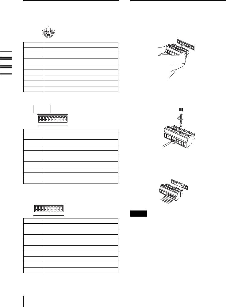
VISCA RS-232C 8 DIN
RS-232C
3TXD IN
4GND
5RXD IN
6GND
VISCA RS-422 ( 9 )
RS-422
VISCA
1 |
9 |
5GND
6RXD IN
7 RXD IN +
8TXD IN
9TXD IN +
TALLY/CONTACT 9
TALLY/CONTACT
1 |
9 |
1CAMERA 1
2CAMERA 2
3CAMERA 3
4CAMERA 4
5CAMERA 5
6CAMERA 6
7CAMERA 7
8GND
9GND
VISCA RS-422
1 VISCA RS-422
1
9
2 AWG No.28 18

3 VISCA RS-422 VISCA RS-422
1 

9
GND
VISCA RS-422 VISCA RS-232C
VISCA RS-422 1.2 km
JP 18

19 JP

Owner’s Record
The model and serial numbers are located on the bottom. Record the serial number in the space provided below. Refer to these numbers whenever you call upon your Sony dealer regarding this product.
Model No. RM-BR300
Serial No.
WARNING
To prevent fire or shock hazard, do not expose the unit to rain or moisture.
To avoid electrical shock, do not open the cabinet. Refer servicing to qualified personnel only.
WARNING
Use an AC power adapter provided with this equipment as a power supply source. Any other power sources may result in hazards such as a fire.
Disconnect device of this equipment is the mains plug of the AC adapter.
The mains plug on this equipment must be used to disconnect mains power.
Please ensure that the socket outlet is installed near the equipment and shall be easily accessible.
In the event of abnormal operations, disconnect the mains plug.
IMPORTANT
Nameplate is located on the bottom.
ATTENTION
The electromagnetic fields at the specific frequencies may influence the picture of this unit.
For customers in the U.S.A.
This equipment has been tested and found to comply with the limits for a Class B digital device, pursuant to Part 15 of the FCC Rules. These limits are designed to provide reasonable protection against harmful interference in a residential installation. This equipment generates, uses, and can radiate radio frequency energy and, if not installed and used in accordance with the instructions, may cause harmful interference to radio communications. However, there is no guarantee that interference will not occur in a particular installation. If this equipment does cause harmful interference to radio or television reception, which can be determined by turning the equipment off and on, the user is encouraged to try to correct the interference by one or more of the following measures:
–Reorient or relocate the receiving antenna.
–Increase the separation between the equipment and receiver.
–Connect the equipment into an outlet on a circuit different from that to which the receiver is connected.
–Consult the dealer or an experienced radio/TV technician for help.
If you have any questions about this product, you may call:
Sony's Business Information Center (BIC) at 1-800-686-Sony (7669)
or Write to: Sony Customer Information Services Center
6900-29, Daniels Parkway, PMB 330 Fort Myers, Florida 33912
Declaration of Conformity
Trade Name: |
SONY |
Model No: |
RM-BR300 |
Responsible Party: Sony Electronics Inc. |
|
Address: |
16450 W. Bernardo Dr, San |
|
Diego, CA 92127 U.S.A. |
Telephone Number:858-942-2230
This device complies with part 15 of the FCC Rules. Operation is subject to the following two conditions:
(1)This device may not cause harmful interference, and
(2)this device must accept any interference received, including interference that may cause undesired operation.
You are cautioned that any changes or modifications not expressly approved in this manual could void your authority to operate this equipment.
The shielded interface cable recommended in this manual must be used with this equipment in order to comply with the limits for a digital device pursuant to Subpart B of Part 15 of FCC Rules.
INTERFACE CABLE
This device requires shielded interface cables to comply with FCC emission limits.
GB 2
Table of Contents |
|
Overview |
|
Features .................................................................. |
4 |
Precautions ............................................................. |
4 |
Location and Function of Parts ............................ |
5 |
Connections and Operations |
|
Connections ............................................................ |
8 |
Connecting a Camera Equipped with a VISCA |
|
RS-232C Connector ......................................... |
8 |
Connecting a Camera Equipped with a VISCA |
|
RS-422 Connector ............................................ |
9 |
Connecting Multiple Cameras Equipped with |
|
VISCA RS-232C Connector ............................ |
9 |
Connecting Multiple Cameras Equipped with |
|
VISCA RS-422 Connector ............................. |
10 |
Connecting the BRU-300/300P Optical Multiplex |
|
Unit ................................................................. |
11 |
Connecting a Video Switcher ........................... |
12 |
Turning on the Power .......................................... |
12 |
Storing the Camera Settings in Memory |
|
– Presetting Feature ............................................. |
13 |
Appendix |
|
Troubleshooting ................................................... |
15 |
Specifications ........................................................ |
16 |
Dimensions ....................................................... |
16 |
Pin Assignments ............................................... |
17 |
Using the VISCA RS-422 Connector Plug ...... |
18 |
GB
Table of Contents 3 GB

Overview
Overview
Features
The optical three-axis joystick allows comfortable pan/tilt/zoom operations.
Easy operation of versatile camera adjustments
Using the buttons on the unit, you can easily perform various camera adjustments such as auto focusing, onepush auto focus adjustment, AE adjustment, one-push auto white balance adjustment and backlight compensation.
The VISCA RS-232C/RS-422 communication interfaces allow high-speed, long-distance communication.
The unit is capable of controlling up to seven cameras connected in daisy chain.
A tally lamp input/contact output terminal (9- pin connector plug) allows connection of a video switcher.
Preset feature to save camera settings
The unit allows saving up to 16 combinations* of camera settings such as pan/tilt/zoom positions and other camera adjustment values in the memory of the camera.
*The number of positions to be saved differs depending on the connected camera
Controllable Sony VISCA cameras
The unit can control the following cameras:
•BRC-300/300P 3CCD Color Video Camera
•EVI-D100/D100P Color Video Camera
•EVI-D70/D70P Color Video Camera
•EVI-D30/D30P Color Video Camera
This manual explains the functions of the unit for the EVI-D100/D100P, EVI-D70/D70P and EVI -D30/D30P cameras.
For functions when the BRC-300/300P is connected, refer to the Operating Instructions supplied with the BRC-300/300P.
Note
The operable functions are limited to those that the camera is equipped with.
Precautions
Operating or storage location
Operating or storing the unit in the following locations may cause damage to the unit:
•Extremely hot or cold places (Operating temperature: 0°C to +40°C [32°F to 104°F])
•Exposed in direct sunlight for a long time, or close to heating equipment (e.g., near heaters)
•Close to sources of strong magnetism
•Close to sources of powerful electromagnetic radiation, such as radios or TV transmitters
•Locations subject to strong vibration or shock
Ventilation
To prevent heat buildup, do not block air circulation around the unit.
Transportation
When transporting the unit, repack it as originally packed at the factory or in materials equal in quality.
Cleaning
•Use a soft, dry cloth to clean the external surfaces of the unit. Stubborn stains can be removed using a soft cloth dampened with a small quantity of detergent solution, then wipe dry.
•Do not use volatile solvents such as alcohol, benzene or thinners as they may damage the surface finishes.
GB 4 Features / Precautions
Location and Function
of Parts
This manual focuses on the operations of the RMBR300 when it is used with cameras other than BRC300/300P.
For operations with the BRC-300/300P, refer to the Operating Instructions supplied with the BRC-300/ 300P.
Front
890qaqsqd qf qg
1 |
|
|
|
|
|
|
|
|
|
|
|
|
|
|
VALUE |
LOCK |
|
|
PANEL |
|
BLACK |
PAN-TILT |
ONE PUSH |
|
|
||
2 |
|
|
|
|
|
|
|
MENU |
|||||
|
|
|
|
|
LIGHT |
|
LIGHT |
RESET |
AWB |
|
|
||
– |
+ |
|
RESET |
|
|
|
|
|
|
|
|
|
|
|
|
R |
|
PRESET |
|
|
|
POSITION |
|
|
|
|
|
|
|
|
MODE |
|
|
|
|
|
|
|
|||
|
BRIGHT |
|
|
|
|
|
|
|
|
|
|
|
|
3 |
|
|
|
SHIFT |
1 |
2 |
3 |
|
4 |
5 |
6 |
7 |
8 |
|
|
|
|
9 |
10 |
11 |
|
12 |
13 |
14 |
15 |
16 |
|
– |
+ |
|
L/R |
STD |
REV |
|
|
|
|
|
|
|
|
|
|
|
|
|
|
|
|
|
|
||||
4 |
|
B |
|
DIRECTION |
|
|
|
CAMERA |
|
|
|
|
|
|
|
|
|
|
|
|
|
|
|
|
|||
|
|
AUTO |
|
|
|
|
|
|
|
|
|
|
|
FOCUS |
AUTO |
POWER |
1 |
2 |
3 |
|
4 |
5 |
6 |
7 |
|
||
|
|
MANUAL |
|
|
|||||||||
5 NEAR |
|
ONE PUSH |
|
|
|
|
|
|
|
|
|
|
|
FAR |
AF |
|
|
|
|
|
|
|
|
|
|
||
6 |
|
|
|
|
|
|
|
|
|
|
|
|
|
7 |
|
|
|
qhqjqk |
|
ql |
|
|
w; |
||||
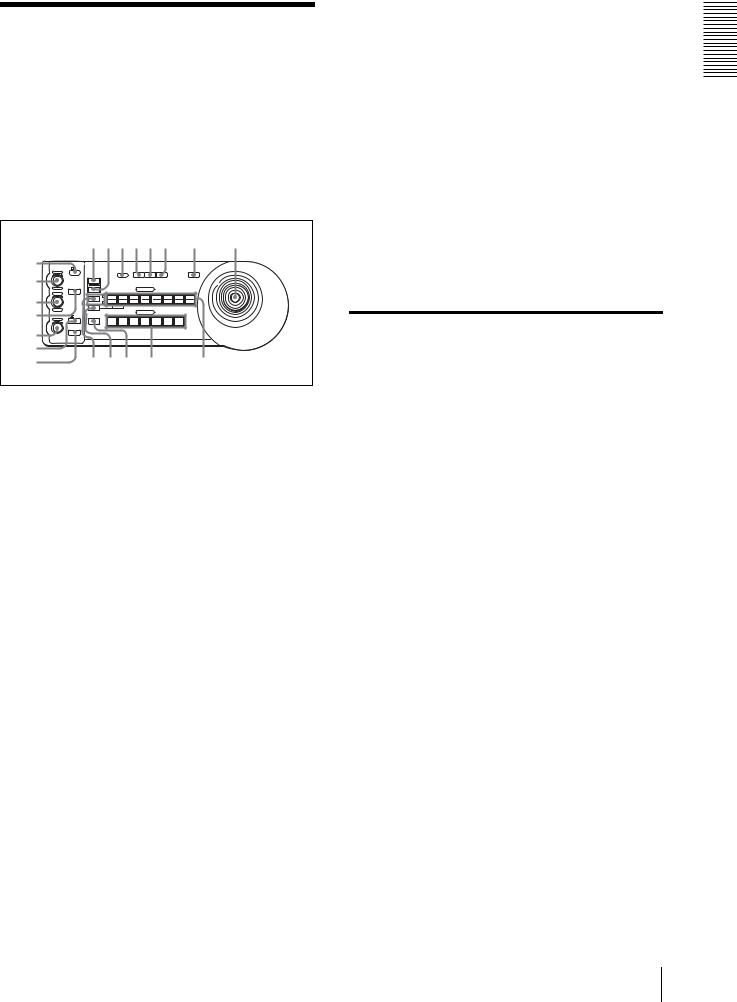
ALOCK button and indicator
Press the LOCK button for more than one second, and the LOCK indicator lights and the values set by the VALUE/R, BRIGHT/B and FOCUS controls are locked. (The indicators of the locked controls are turned off.).
The AUTO/MANUAL button is also disabled. Press the LOCK button for more than one second again to unlock the controls and buttons.
BVALUE/R control
When the brightness adjustment mode is selected with the MODE button (with the VALUE indicator lit), this control adjusts the value of the item (SHUTTER or IRIS) selected on the camera. When the white balance adjustment mode is selected with the MODE button (with the R indicator lit), this control adjusts the R. GAIN (red gain) (except the EVI-D30/D30P).
When the VALUE indicator is lit, the function of the control varies according to the exposure mode selected on the camera. For details, see “Functions of the VALUE and BRIGHT controls” on page 5.
CBRIGHT/B control
When the brightness adjustment mode is selected with the MODE button (with the BRIGHT indicator lit), this control adjusts the value of the brightness of the camera, etc.
When the white balance adjustment mode is selected with the MODE button (with the B indicator lit), this control adjusts the B. GAIN (blue gain) (except the EVI-D30/D30P).
When the BRIGHT indicator is lit, the function of the control varies according to the exposure mode selected on the camera. For details, see “Functions of the VALUE and BRIGHT controls” on page 5.
Functions of the VALUE and BRIGHT controls
The functions of the VALUE control and the BRIGHT control change according to the exposure mode setting on the camera, as follows:
Exposure mode |
Function of |
Function of |
on the camera |
VALUE control |
BRIGHT control |
|
|
|
FULL AUTO |
Not used |
Exposure |
|
|
compensation level |
|
|
control* |
|
|
|
SHUTTER Pri |
Shutter speed |
Exposure |
|
control |
compensation level |
|
|
control* |
|
|
|
IRIS Pri |
Iris control |
Exposure |
|
|
compensation level |
|
|
control* |
|
|
|
BRIGHT |
Not used |
Brightness level |
|
|
control |
|
|
|
MANUAL |
Shutter speed |
Iris control |
|
control |
|
|
|
|
*When the exposure compensation function is activated on the camera.
DMODE button
Press this button to select the function of the VALUE/R control and BRIGHT/L control.
When the brightness adjustment mode is selected, the VALUE and BRIGHT indicators are lit. When the white balance adjustment mode is selected, the R and B indicators are lit.
EFOCUS control
This control is enabled when MANUAL is selected with the AUTO/MANUAL button. Turn the control counterclockwise (toward NEAR) to focus on a near subject, and clockwise (toward FAR) to focus on a far subject.
Overview
Location and Function of Parts 5 GB

Overview
FAUTO/MANUAL button and AUTO indicator
Press this button to select focus mode AUTO or MANUAL.
When AUTO is selected, the AUTO indicator lights and the camera focuses automatically on the subject in the center of the screen. The FOCUS control and the ONE PUSH AF button are disabled.
When MANUAL is selected, the FOCUS control and the ONE PUSH AF button are enabled (with the FOCUS indicator lit).
GONE PUSH AF button
This button is enabled when MANUAL is selected with the AUTO/MANUAL button. Press the button to perform the one-push auto focus function (except the EVI-D30/D30P).
HRESET button
Hold down this button and press POSITION button 1 to 16, and the memory of the camera corresponding to the pressed POSITION button is cleared to the factory-preset conditions.
When multiple cameras are connected, the camera addresses are set by holding down this button and pressing the POWER button.
IPRESET button
Hold down this button and press POSITION button 1 to 16, and the current camera settings are stored in the memory of the camera corresponding to the pressed POSITION button.
JPANEL LIGHT button
Press this button to illuminate all the POSITION buttons and CAMERA buttons. Press the button again to turn off the illumination.
KBACK LIGHT button
When the FULL AUTO exposure mode is selected on the camera, press this button to enable the backlight compensation function of the camera. Press it again to disable the function.
LPAN-TILT RESET button
Press this button to reset the pan/tilt position of the camera to the initial conditions.
MONE PUSH AWB button
When the ONE PUSH white balance mode is selected on the camera, press this button to perform the one-push white balance adjustment.
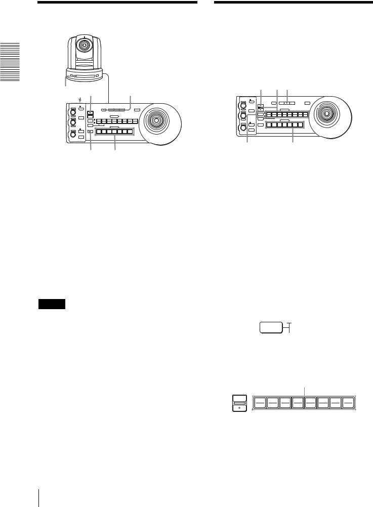
NMENU button
For the BRC-300/300P camera, press this button to display the menu of the camera, return to the main menu or turn off the menu.
For other cameras, press this button to turn the onscreen data display on or off.
OJoystick
The joystick is used for pan/tilt and zoom operations. Select the camera you want to control using the CAMERA buttons and operate the joystick.
Panning and tilting
When you incline the joystick right and left, the camera pans. When you incline it forward or backward, the camera tilts.
The pan/tilt speed changes according to the angle of the inclination.
When you release the joystick, the camera movement stops.
Zooming
When you turn the dial on the upper part of the joystick clockwise, the subject becomes larger (zoom in). When you turn it counterclockwise, the subject becomes smaller (zoom out).
To face the camera back to the front
When you press the button on the top of the joystick for one or two seconds with or without the menu displayed, the pan/tilt/zoom are reset and the camera returns to the front.
PSHIFT button and indicators
Press this button for more than one second to select the function of the POSITION buttons for positions 1 to 8 or positions 9 to 16.
The upper indicator lights for positions 1 to 8, and the lower indicator for positions 9 to 16.
QL/R DIRECTION button
The camera is preset to face toward the right whenever the joystick is inclined to the right. Hold down this button and press POSITION button 2 (REV) to reverse the pan direction to the direction in which you incline the joystick. To reset the direction, hold down this button and press POSITION button 1 (STD).
GB 6 Location and Function of Parts
RPOWER button
Press this button to light the CAMERA button(s) corresponding to the status of the connected camera(s).
Blue: The power of the camera is on.
Yellow green: The camera is in standby mode. Off: No camera is connected.
Hold down this button and press CAMERA button 1 to 7 to turn on/off the power of the camera corresponding to the pressed button.
SCAMERA buttons
Press one of the buttons to select the camera from among those connected. The selected CAMERA button lights in blue.
TPOSITION buttons
You can store various camera settings such as the pan, tilt and zoom positions to the memory of the camera corresponding to each POSITION button, and load the settings in the memory.
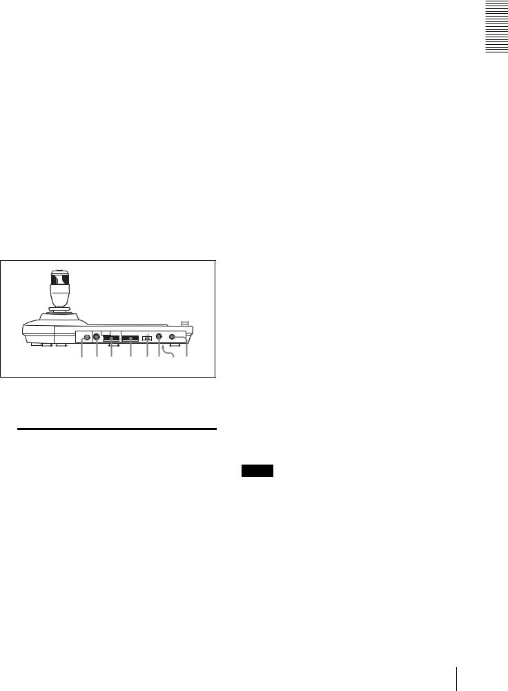
Rear/Bottom |
|
|
|
|
|
MODE RS-232C |
VISCA |
RS-422 |
TALLY/CONTACT |
CONTACT(TALLY) ! ON/OFF |
|
|
|
|
|
|
TALLY |
|
1 |
9 |
1 |
9 |
CONTACT DC IN 12V |
|
|
|
|
|
|
wa ws wd |
|
wf wg wh wj wk |
|||
UMODE selector
Select the position corresponding to the VISCAcontrollable camera to be connected.
Switch position |
Camera mode |
0 |
Automatically selected (default) |
|
|
1 |
BRC-300/300P |
|
|
2 |
EVI-D70/D70P |
|
|
3 |
EVI-D100/D100P |
|
|
4 |
EVI-D30/D30P |
|
|
VVISCA RS-232C connector
Connect to the VISCA RS-232C IN connector of the camera or the BRU-300/300P Optical Multiplex Unit.
WVISCA RS-422 connector
Connect to the VISCA RS-422 connector of the camera or the BRU-300/300P Optical Multiplex Unit.
An RS-422 connector plug is attached at the factory.
XTALLY/CONTACT connector
This connector is used for the tally lamp input or the contact output.
Select the function of the connector using the TALLY/CONTACT selector.
An RS-422 connector plug is attached at the factory.
YTALLY/CONTACT selector
Select the function of the TALLY/CONTACT connector.
TALLY: The tally lamp of the camera selected with the connected switcher lights.
CONTACT: The contact output corresponding to the camera address selected with this unit is shortcircuited against the connected switcher.
CONTACT (TALLY): The contact output corresponding to the camera address selected with this unit is short-circuited against the connected switcher and the tally lamp of the camera selected with the connected switcher lights.
wh DC IN 12V connector
Connect the supplied AC power adaptor.
wj DIP switches (bottom)
Switch 1 (RS-232C/RS-422 selector)
Set to ON for RS-422, or OFF for RS-232C.
Switch 2 (Communication baud rate selector)
Set to ON for 38400bps, or OFF for 9600bps.
wk ON/OFF switch
Press this switch to turn on/off this unit.
Note
Set the switches before you turn on the power of this unit. Otherwise, the setting is not effective.
Overview
Location and Function of Parts 7 GB
Operations and Connections
Connections and Operations
Connections
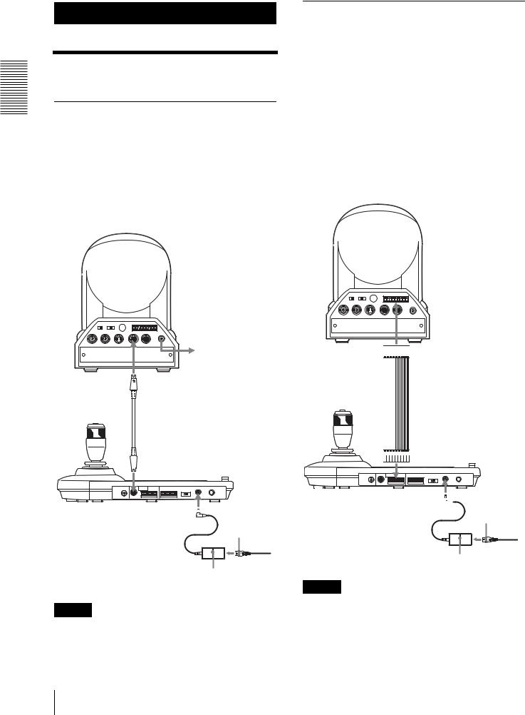
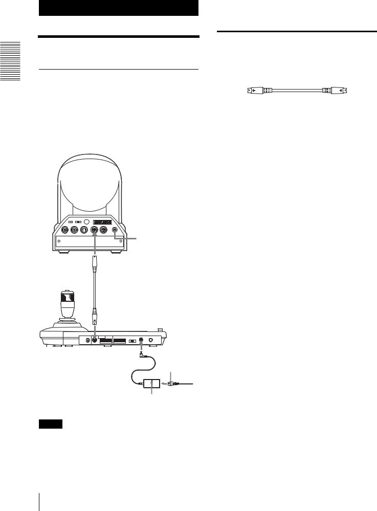
Connecting a Camera Equipped with a VISCA RS-232C Connector
1 Connect this unit to the camera using the RS-232C connecting cable supplied with this unit.
2 Connect this unit to an AC outlet using the supplied AC power adaptor and AC power cord.
Camera
Connecting cables
Use the following connecting cable to connect devices in this system.
Cable |
Part No. |
Number |
RS-232C cable |
1-590-879-3X |
1 |
(3m (10feet)) |
|
|
|
|
|
RS-232C cable
R
1 2 3
OFF 

 ON
ON
75 IR SELECT
EXT SYNC IN  VIDEO
VIDEO  S VIDEO
1 2 3 4 5 6 7 8 9 |
|
VISCA RS-422 |
! |
IN VISCA RS-232C OUT |
DC IN |
12V |
 to AC outlet
 VISCA RS-232C IN
 RS-232C cable (supplied) (SONY: 1-590-879-3X)
VISCA RS-232C
DC IN 12V
AC power cord (supplied)
to AC outlet
AC power adaptor (supplied)
Note
When using the VISCA RS-232C connectors, check that the DIP switch on the bottom of this unit (page 7) is set to RS-232C.
GB 8 Connections
Connecting a Camera Equipped with a VISCA RS-422 Connector
You can use the VISCA RS-422 connectors to connect this unit to the camera instead of the VISCA RS-232C connectors. Use of the VISCA RS-422 connectors allows the connection up to 1,200 m (3,937 feet) away. Prepare the connecting cable using the RS-422 connector plugs that come with this unit.
For making the cable, refer to the pin assignments of the VISCA RS-422 connector (page 17).
For the use of the RS-422 connector plugs, see page 18.
Camera
to AC outlet


 VISCA RS-422
 VISCA RS-422 cable

 VISCA RS-422
DC IN 12V
AC power cord (supplied)
to AC outlet AC power adaptor
(supplied)
Notes
•When using the VISCA RS-422 connectors, check that the DIP switch on the bottom of this unit (page 7) is set to RS-422.
•When the connections using the VISCA RS-422 connectors are made, the VISCA RS-232C connection is not available.
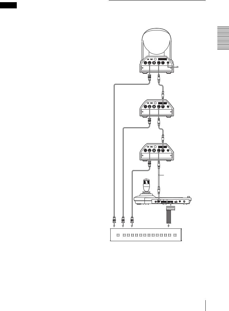
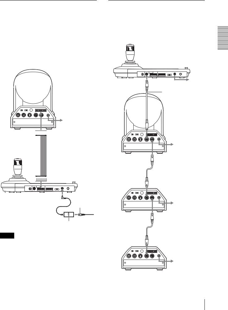
Connecting Multiple Cameras Equipped with VISCA RS-232C Connector
Connections with the VISCA RS-232C cables (cross type) enable control of up to seven cameras with a single RM-BR300 Remote Control Unit.
VISCA RS-232C |
to AC outlet |
|
RS-232C cable (supplied) |
|
(SONY: 1-590-879-3X) |
 to VISCA RS-232C IN
|
1 |
2 |
3 |
R |
1 2 3 4 5 6 7 8 9 |
|
|
|
|
|
|||
OFF |
ON |
|
|
|
|
|
75 |
IR SELECT |
|
VISCA RS-422 |
! |
||
|
|
|
|
|
||
EXT SYNC IN |
VIDEO |
|
S VIDEO IN VISCA RS-232C OUT |
DC IN |
||
|
12V |
|||||
|
|
|
|
|
|
to AC outlet |
First camera |
|
VISCA RS-232C OUT |
||||
|
|
|
|
|
RS-232C cable |
|
|
|
|
|
|
VISCA RS-232C IN |
|
|
1 |
2 |
3 |
R |
1 2 3 4 5 6 7 8 9 |
|
|
|
|
|
|||
OFF |
ON |
|
|
|
|
|
75 |
IR SELECT |
|
VISCA RS-422 |
! |
||
|
|
|
|
|
||
EXT SYNC IN |
VIDEO |
|
S VIDEO IN VISCA RS-232C OUT |
DC IN |
||
|
12V |
|||||
|
|
|
|
|
|
to AC outlet |
Second camera |
|
VISCA RS-232C OUT |
||||
|
|
|
|
|
|
|
|
|
|
|
|
RS-232C cable |
|
|
|
|
|
|
VISCA RS-232C IN |
|
|
1 |
2 |
3 |
R |
1 2 3 4 5 6 7 8 9 |
|
|
|
|
|
|||
OFF |
ON |
|
|
|
|
|
75 |
IR SELECT |
|
VISCA RS-422 |
! |
||
|
|
|
|
|
||
EXT SYNC IN |
VIDEO |
|
S VIDEO IN VISCA RS-232C OUT |
DC IN |
||
|
12V |
|||||
|
|
|
|
|
|
to AC outlet |
Third to Seventh camera
Operations and Connections
Connections 9 GB
Operations and Connections
Note
When using the VISCA RS-232C connectors, check that the DIP switch on the bottom of this unit (page 7) is set to RS-232C.
To assign camera addresses
Before operating, you must assign the camera addresses to the connected cameras as follows. Then you can switch the camera to be controlled simply by pressing the corresponding CAMERA button.
1 Turn on the power of all the connetcted cameras and this unit.
2 Hold down the RESET button and press the POWER button on this unit.
The unit recognizes the connected cameras and assigns them camera addresses 1 to 7 automatically in the connected order.
3 Press the POWER button on this unit and check that the CAMERA buttons light.
The number of the lit CAMERA buttons indicates how many cameras have the addresses assigned. Now you can switch the camera you want to control by pressing the CAMERA button.
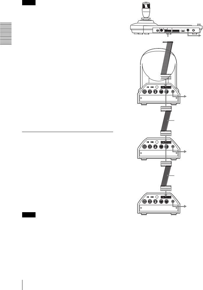
Connecting Multiple Cameras Equipped with VISCA RS-422 Connector
Connection via the VISCA RS-422 connectors enables control of multiple cameras. This allows the connection up to 1,200 m (3,937 feet) away.
Prepare the connecting cable using the RS-422 connector plug that comes with this unit.
For making the cable, refer to the pin assignments of the VISCA RS-422 connector (page 17).
For the use of the RS-422 connector plugs, see page 18. For the wiring diagram of VISCA RS-422 connection, refer to the Operating Instructions supplied with the BRC-300/300P.
Notes
•When using the VISCA RS-422 connectors, check that the DIP switch on the bottom of this unit (page 7) is set to RS-422.
•When the connections using the VISCA RS-422 connectors are made, the VISCA RS-232C connection is not available.
 VISCA RS-422 to AC outlet
 VISCA RS-422 cable


 to VISCA RS-422
|
1 |
2 |
3 |
R |
1 2 3 4 5 6 7 8 9 |
|
OFF |
ON |
|
|
|
|
|
75 |
IR SELECT |
|
VISCA RS-422 |
! |
||
|
|
|
|
|
||
EXT SYNC IN |
VIDEO |
|
S VIDEO IN VISCA RS-232C OUT |
DC IN |
||
|
12V |
|||||
|
|
|
|
|
|
to AC outlet |
First camera |
|
|
|
|
VISCA RS-422 |
|
|
|
|
|
|
|
|
|
|
|
|
|
|
VISCA RS-422 cable |
|
1 |
2 |
3 |
R |
1 2 3 4 5 6 7 8 9 |
|
|
|
|
|
|||
OFF |
ON |
|
|
|
|
|
75 |
IR SELECT |
|
VISCA RS-422 |
! |
||
|
|
|
|
|
||
EXT SYNC IN |
VIDEO |
|
S VIDEO IN VISCA RS-232C OUT |
DC IN |
||
|
12V |
|||||
|
|
|
|
|
|
to AC outlet |
Second camera |
|
VISCA RS-422 |
||||
|
|
|
|
|
|
|
|
|
|
|
|
|
VISCA RS-422 cable |
|
|
|
|
|
|
VISCA RS-422 |
|
1 |
2 |
3 |
R |
1 2 3 4 5 6 7 8 9 |
|
|
|
|
|
|||
OFF |
ON |
|
|
|
|
|
75 |
IR SELECT |
|
VISCA RS-422 |
! |
||
|
|
|
|
|
||
EXT SYNC IN |
VIDEO |
|
S VIDEO IN VISCA RS-232C OUT |
DC IN |
||
|
12V |
|||||
to AC outlet
Third to Seventh camera
GB 10 Connections
 Loading...