


3-860-688-11(1)
RMO-S594
-DW
MO Disk Unit RMO-S591
-DW
User’s Guide
Mode d’emploi
Bedienungsanleitung
Guía del usuario
Istruzioni per l’uso

RMO-S594 -DW
MO Disk Unit RMO-S591
-DW
Sony Corporation Printed in Japan © 1997
Safety Regulations
Owner’s Record
The model and serial numbers are located on the bottom of the unit. Record the serial number in the space provided below.
Refer to them whenever you call upon your Sony dealer regarding this product.
Model No. RMO-S594-DW, RMO-S591-DW Serial No._________________________
Information
For the customer in the U.S.A.
You are cautioned that any changes or modifications not expressly approved in this manual could void your authority to operate this equipment.
This equipment has been tested and found to comply with the limits for a Class B digital device, pursuant to Part 15 of the FCC Rules. These limits are designed to provide reasonable protection against harmful interference in a residential installation. This equipment generates, uses, and can radiate radio frequency energy and, if not installed and used in accordance with the instructions, may cause harmful interference to radio communications. However, there is no guarantee that interference will not occur in a particular installation. If this equipment does cause harmful interference to radio or television reception, which can be determined by turning the equipment off and on, the user is encouraged to try to correct the interference by one or more of the following measures:
–Reorient or relocate the receiving antenna.
–Increase the separation between the equipment and receiver.
–Connect the equipment into an outlet on a circuit different from that to which the receiver is connected.
–Consult the dealer or an experienced radio/TV technician for help.
This device requires shielded interface cables to comply with FCC emission limits.
WARNING
To prevent fire or shock hazard, do not expose the unit to rain or moisture.
To avoid electrical shock, do not open the cabinet. Refer servicing to qualified personnel only.
CAUTION
As the laser beam used in the RMO-S594- DW/S591-DW is harmful to the eyes, do not attempt to disassemble the unit.
Refer servicing to qualified personnel only.
This label is affixed inside the unit.
DANGER LASER RADIATION WHEN OPEN.
AVOID DERECT EXPOSURE TO BEAM.
DANGER RADIATIONS DU LASER EN CAS D’OUVERTURE.
EVITER TOUTE EXPOSITION DIRECTE AU FAISCEAU.
VORSICHT LASERSTRAHLUNG. WENN ABDECKUNG GEöFFNET. NICHT DEM STRAHL AUSSETZEN.
4-630-960-01
CAUTION:
TO PREVENT ELECTRIC SHOCK, DO NOT USE THIS POLARIZED AC PLUG WITH AN EXTENSION CORD, RECEPTACLE OR OTHER OUTLET UNLESS THE BLADES CAN BE FULLY INSERTED TO PREVENT BLADE EXPOSURE.
This MO disk unit is classified as a CLASS 1 LASER PRODUCT.
The CLASS 1 LASER PRODUCT label is located on the bottom exterior.
CLASS 1
LASER PRODUCT
LASER KLASSE 1
PRODUKT 4-627-223-01
NOTICE
Use the power cord set approved by the appropriate testing organization for the specific countries where this unit is to be used.
2

LUOKAN 1 LASERLAITE
KLASS 1 LASER APPARAT
VAROITUS!
Laitteen käyttäminen muulla kuin tässä käyttöohjeessa mainitulla tavalla saattaa altistaa käyttäjän turvallisuusluokan 1 ylittävälle näkymättömälle lasersäteilylle.
VARNING
Om apparaten används på annat sätt än i denna bruksanvisning specificerats, kan användaren utsättas för osynlig laserstrålning, som överskrider gränsen för laserklass 1.
ADVARSEL USYNLIG LASERSTRÅLING VED ÅBNING, UNDGÅ UDSÆTTELSE FOR STRÅLING. ADVARSEL USYNLIG LASERSTRÅLING NÅR DEKSEL ÅPNES, UNNGÅ EKSPONERING FOR STRÅLEN. VARNING OSYNLIG LASERSTRÅLNING NÄR DENNA DEL ÄR ÖPPNAD, STRÅLEN ÄR FARLIG. VARO! AVATTAESSA OLET ALTTIINA NÄKYMÄTÖN LASERSÄTEILYLLE, ÄLÄ KATSO SÄTEESEN.
4-625-571-02
Denne merkelappen er festet på apparatets innside.
Denna varningsskylt finns inuti apparaten. Denne mærkat sidder indeni apparatet.
Tmä tarra on kiinnitetty laitteen sisään.
Tekniske Data
■ Laser
Type |
Halveder GaAlAs |
|
laser |
Bølgelengde |
685 nm ± 10 nm |
Maksimum utgang |
30 mW |
Specifikationer
■ Laser
Typ |
Halvledarlaser av typ |
|
GaAlAs |
Våglängd |
685 nm ± 10 nm |
Maximal uteffekt |
30 mW |
Specifikationer
■ Laser
Type |
Halvlederlaser |
|
GaAlAs laser |
Bølgelængde |
685 nm ± 10 nm |
Max. udgangseffekt |
30 mW |
Table of Contents |
|
Using this Guide ......................................... |
4 |
Chapter 1 Introduction |
|
Overview .................................................... |
5 |
Features ....................................................... |
5 |
Compatible Disks ....................................... |
6 |
System Configuration ................................. |
6 |
Location and Function of Parts ............... |
7 |
Front Panel .................................................. |
7 |
Rear Panel ................................................... |
8 |
Chapter 2 Getting Started |
|
Component and Accessory Check List .. |
9 |
Connecting the Disk Unit ....................... |
10 |
Setting the SCSI ID.................................. |
11 |
Setting the Disk Unit’s Functions .......... |
11 |
Chapter 3 Using the Disk Unit |
|
Inserting a Disk Cartridge ...................... |
13 |
Ejecting a Disk Cartridge ........................ |
14 |
Chapter 4 Precautions |
|
On the Disk Unit ...................................... |
15 |
Safety Considerations ............................... |
15 |
Damage Prevention .................................. |
15 |
Other Points Requiring Attention ............. |
16 |
On the Disk Cartridges ........................... |
16 |
Protecting Your Data ................................ |
17 |
Cleaning ................................................... |
17 |
Cleaning a Disk ........................................ |
17 |
Appendix |
|
Specifications .......................................... |
18 |
Disk Unit .................................................. |
18 |
Optional Accessories ................................ |
19 |
Table of Contents |
3 |

Using this Guide
This guide covers the use and operation of the RMO-S594-DW/S591-DW Magneto-Optical Disk Unit (called the “disk unit” thereafter). Do not attempt to use the disk unit without first carefully reading this guide. When finished, keep it handy for future reference.
The guide is divided into the following sections.
Chapter 1 Introduction
This chapter contains a general overview of the RMO-S594-DW/S591-DW disk unit, touching upon its features, system configuration, and the location and function of its parts.
Chapter 2 Getting Started
This chapter explains how to connect the disk unit to the host computer and other SCSI peripheral devices. It also explains how to set the disk unit’s functions and the SCSI ID. Refer to this chapter when setting up the disk unit.
Chapter 3 Using the Disk Unit
In this chapter, you learn how to turn on the disk unit, and how to insert and eject a disk cartridge. Refer to this chapter when you are ready to actually begin using the disk unit.
Chapter 4 Precautions
This chapter contains precautions regarding the use and operation of the disk unit and magnetooptical disk cartridges.
It also discusses cleaning of disks.
Be sure to refer to this chapter before using the disk unit.
Appendix
The Appendix contains an explanation of the disk unit’s main specifications.
Notes:
•The manufacturer disclaims all responsibility for any losses incurred through malfunction or use of this product.
•The manufacturer does not warrant the security of data stored using this product. To guard accidental data loss, frequent backup of important data is highly recommended.
•Reproduction of the contents of this manual, in whole or in part, is prohibited.
4 Table of Contents

 Chapter 1 Introduction
Overview
Features
The RMO-S594-DW/S591-DW Magneto-Optical Disk Unit has the following features:
•Magneto-optical technology enables repeated writing and erasing of data on the disk.
•The disk unit automatically senses the type of disk being inserted, enabling the free use of both 650-Mbytes (594-Mbytes), 1.3-Gbytes (1.2-Gbytes) and 2.6 Gbytes (2.3 Gbytes)disks indifferently.
•Direct-Overwrite MO disks can be used. The writing performance of this disk unit is 1.5 to 2.0 times faster than that of the earlier MO Disk Unit.
•A maximum of 2.6 Gbytes (1,024 bytes/sector) or 2.3 Gbytes (512 bytes/sector) of data can be written on the two sides of a 5.25-inch magnetooptical disk. This is equivalent to about 1600– 1800 times the capacity of a conventional 3.5- inch floppy disk (2HD).
•Any disk conforming to the internationally accepted CCS (continuous/composite servo) or CCW (continuous composite write-once) format can be used in this disk unit.
•This disk unit employs SCSI-2 (Small Computer System Interface-2).
•The 3,600 min-1 (3,600 rpm) high-speed spindle motor enables data transfer rates of
2.03– 4.06 Mbytes/s (1,024 bytes/sector) or
1.78– 3.56 Mbytes/s (512 bytes/sector).
•The low-profile, light-weight optical pick-up yields average seek times of 25ms.
•Use of a highly reliable error correction code (ECC) system keeps the error rate as low as 10-12.
•Optimum operation environment is provided through use of a large, 4MB(S594-DW)/ 1MB(S591-DW) buffer and optimized cache control algorithm. (Write cache can be enabled or disabled. For details, see “Setting the Disk Unit’s Functions” on page 11.)
Chapter 1 Introduction |
5 |
Compatible Disks
The RMO-S594-DW/S591-DW can use the following Sony 5.25-inch MO Disks:
Standard |
Sector format |
Type* |
Capacity |
Sony equivalent |
|
|
|
|
|
|
|
ISO/IEC CD 14517 |
1024 |
bytes/sector |
R/W(DW) |
Approx. 2.6 G bytes |
DOM-2600B |
|
|
|
|
|
|
ISO/IEC CD 14517 |
512 |
bytes/sector |
R/W(DW) |
Approx. 2.3 G bytes |
DOM-2300B |
|
|
|
|
|
|
ISO/IEC CD 14517 |
1024 |
bytes/sector |
R/W |
About 2.6 G bytes |
EDM-2600B |
|
|
|
|
|
|
ISO/IEC CD 14517 |
512 |
bytes/sector |
R/W |
About 2.3 G bytes |
EDM-2300B |
|
|
|
|
|
|
ISO/IEC 13549 |
1024 |
bytes/sector |
R/W |
About 1.3 G bytes |
EDM-1300B |
|
|
|
|
|
|
ISO/IEC 13549 |
512 |
bytes/sector |
R/W |
About 1.2 G bytes |
EDM-1200B |
|
|
|
|
|
|
ISO/IEC 10089 |
1024 |
bytes/sector |
R |
About 650 M bytes |
EDM-650B |
|
|
|
|
|
|
ISO/IEC 10089 |
512 |
bytes/sector |
R |
About 600 M bytes |
EDM-600B |
|
|
|
|
|
|
ISO/IEC CD 14517 |
1024 |
bytes/sector |
WO |
About 2.6 G bytes |
CWO-2600B |
|
|
|
|
|
|
ISO/IEC CD 14517 |
512 |
bytes/sector |
WO |
About 2.3 G bytes |
CWO-2300B |
|
|
|
|
|
|
ISO/IEC 13549 |
1024 |
bytes/sector |
WO |
About 1.3 G bytes |
CWO-1300B |
|
|
|
|
|
|
ISO/IEC 13549 |
512 |
bytes/sector |
WO |
About 1.2 G bytes |
CWO-1200B |
|
|
|
|
|
|
ISO/IEC 11560 |
1024 |
bytes/sector |
R |
About 650 M bytes |
CWO-650B |
|
|
|
|
|
|
ISO/IEC 11560 |
512 |
bytes/sector |
R |
About 600 M bytes |
CWO-600B |
|
|
|
|
|
|
*R/W(DW):Rewritable(Direct-Overwrite MO), R/W:Rewritable(MO), WO:Write Once, R:Read Only
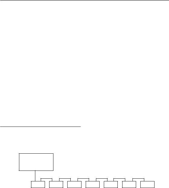
System Configuration
The disk unit should be used with a host computer equipped with SCSI.
A maximum of seven peripheral devices can be linked in a daisy chain on the SCSI bus, and controlled with SCSI-2 commands.
Host computer
SCSI cable
|
|
|
|
RMO-S594-DW/S591-DW disk unit |
SCSI peripheral devices |
||
Fig. 1-1: System Configuration Example
6 Chapter 1 Introduction
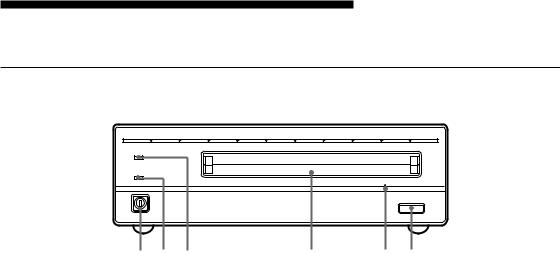
Location and Function of Parts
Front Panel
BUSY
POWER
|
|
EJECT |
1 2 3 |
4 |
5 6 |
|
Fig. 1-2: Front View |
|
1 POWER switch
Push the button to turn the power on and off. The power is on when the button is in the depressed position, and off when fully protruding.
2 POWER indicator
The green lamp lights up when the power is turned on.
3 BUSY indicator
As this disk is inserted and the drive becomes ready for read/write operation, the BUSY indicator turns green. The orange lamp lights up when the disk unit is accessing or writing data. This lamp flashes on and off at about 2- second intervals when the unit overheats, regardless of whether or not a disk is being accessed.
4 Disk insertion slot
5 Emergency eject hole
If the disk cartridge cannot be ejected using the EJECT button 6, turn off the power and insert the supplied emergency eject tool into this hole to trip the emergency eject mechanism. Refer to the section “What to do if the disk does not eject” on page 14 for further details.
6 EJECT button
Press this button to eject the disk cartridge from the disk unit. The EJECT button is disabled with the function switch or software settings prohibit ejection. When the write cache is enabled, it may take a few moments (up to 45 seconds) for the disk to eject because data in the cache must first be written to the disk.
Insert the disk cartridge into this slot. Refer to the section “Inserting a Disk Cartridge” on page 13 for more information.
Chapter 1 Introduction |
7 |

Rear Panel
A B C D E F G H |
AC IN |
1 |
|
|
SCSI ID |
0 |
|
SCSI CONNECTOR |
F.GND |
|
|
|
|
|
|
|
|
|
|
|
|
|
|
|
|
|
|
|
|
|
|
|
|
|
|
1 |
2 |
3 |
4 |
5 6 |
||||||||
|
|
|
|
|
Fig 1-3: Rear View |
|
|
|
|
|||
1 Function switches
Use this switches to set the disk unit’s functions in accordance with the host computer and software being used. Refer to the section“Setting the Disk Unit’s Functions” on page 11 for more information.
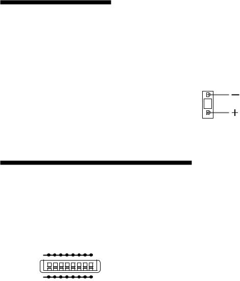
2 SCSI ID switch
Use these switches to set the SCSI ID. Push the “–” button to lower the ID number; push the “+” button to raise the ID number. Refer to the section“Setting the SCSI ID”on page 11 for more information.
3 SCSI connectors
Plug SCSI cables (sold separately) linking the host computer and other SCSI peripherals into these connectors.
Note:
If the disk unit is the last device on the SCSI chain, set function switch F to “1” to turn on the internal terminator. When it is not the last device, make sure that the terminator is off (switch F is set to “0”).
4 Air duct
The air for cooling the disk unit flows through this duct, so be careful not to block its surface or impede the outflow.
5 F.GND (frame ground) terminal
Connect the ground terminals of other devices to the disk unit’s frame ground.
6 AC IN (AC power) connector
Connect the supplied AC power cord to this connector.
8 Chapter 1 Introduction
 Chapter 2 Getting Started
Before setting up your RMO-S594-DW/S591- DW Magneto-Optical Disk Unit, check to see that you have all the required components and accessories. Then, connect the disk unit to the host computer and any other SCSI peripherals
you may be using. After checking to see that all the connections have been properly made, set the SCSI ID using the SCSI ID switch and the disk unit’s functions using the function switches.
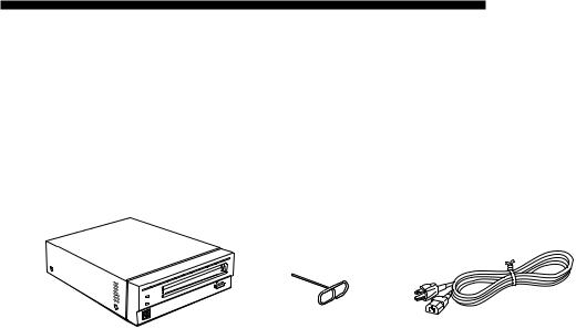
Component and Accessory Check List
Upon opening the carton, check to see that you have all of the components and accessories listed below. Contact your dealer immediately if you find any missing or damaged items.
•RMO-S594-DW/S591-DW Magneto-Optical Disk Unit
•AC power cord
•Emergency eject tool
•User’s Guide
•Guide to Safe Use (Safety Precautions)
RMO-S594-DW/S591-DW |
Emergency eject tool |
AC Power cord |
Magneto-Optical Disk Unit |
|
|
|
|
|
|
Fig 2-1: Items in the Package |
|
Chapter 2 Getting Started |
9 |
Connecting the Disk Unit
You can hook up a maximum of seven SCSI peripheral devices to a single host computer through its SCSI bus.
Use either of the following Sony SCSI cable
(sold separately) to connect the disk unit.
• MOA-C08 (80 cm, full pitch full pitch)
Notes:
•Before connecting the disk unit, be sure to turn off the disk unit and all other devices on the SCSI chain.
•If the disk unit is the last device on the SCSI chain, set the function switch F on the rear panel to “1” to turn on the internal terminator. When it is not the last device, make sure that the terminator is off (function switch F is set to
“0”).
•The total length of the SCSI cables connected to a SCSI chain must not exceed six meters (19 feet 8 1/4 inches).
RMO-S594-DW/S591-DW Magneto-Optical Disk Unit
A B C D E F G H |
AC IN |
1 |
|
|
SCSI ID |
0 |
|
SCSI CONNECTOR |
F.GND |
to SCSI connector |
to AC IN |
|
connector |
SCSI cable |
|
|
|
|
|
|
|
SCSI cable |
|
AC power cord |
||||
(sold separately) |
|
|
|
|
|
|
|
|
(supplied) |
|||||
|
|
|
|
|
|
|
(sold separately) |
|
||||||
|
|
|
|
|
|
|
|
|
|
|
|
|||
|
|
|
|
|
|
|
|
|
|
|
|
|
|
|
|
|
|
|
|
|
|
|
|
|
|
|
|
|
|
|
|
|
|
|
|
|
|
|
|
|
|
|
|
|
|
|
|
|
|
|
|
|
|
|
|
|
|
|
|
|
|
|
|
|
|
|
|
|
|
|
|
|
|
|
to another |
to the host computer or |
to an AC outlet |
|
||
SCSI device |
another SCSI device |
|
Fig 2-2: Connecting the RMO-S594-DW/S591-DW
10 Chapter 2 Getting Started
Setting the SCSI ID
The factory default setting for the SCSI ID is “0.” If necessary, this ID number can be changed using the SCSI ID switch on the rear panel. Be sure to turn off the power before making any changes.
Pushing the “+” button raises the ID number; pushing the “–” button lowers the ID number.
Notes:
•The disk unit will not operate properly unless the SCSI ID has been set correctly.
•Make sure to select a SCSI ID that has not been assigned to another SCSI device.
0
Fig 2-3: SCSI ID Switch
Setting the Disk Unit’s Functions
Use function switches (A – H) on the rear panel to select the disk unit’s functions in accordance with the host computer and software you are using. Be sure to turn off the power before setting the switches.
A B C D E F G H
1
0
Fig 2-4: Function Switches
This disk unit is equipped with a write cache. When the write cache is enabled, never turn off the disk unit power without making sure that all data has been written to the disk from cache memory. Data will be lost if you turn off the power before all data in cache memory has been written to the disk.
Before powering off the disk unit, be sure to eject the disk. Ejecting the disk writes data from cache memory to the disk.
Note:
Even though the drive will flush data periodically to the disk, data may be lost in the case of a power failure.
Chapter 2 Getting Started 11
Table 2-1: Function Switch Settings
Switch |
Function |
|
|
|
|
1 |
0 |
||||
|
|
||||
A |
Parity check |
SCSI parity check is disabled. |
SCSI parity check is |
||
|
|
|
enabled. |
||
B |
Device type |
Peripheral device type |
Peripheral device type |
||
|
|
00H |
|
07H |
|
|
|
(Direct Access Device) |
(Optical Memory Device) |
||
C |
Write cache control |
Disable write cache. |
Enable write cache. |
||
D |
Fast SCSI control |
Fast SCSI compatible |
Not Fast SCSI compatible |
||
E |
Force verify |
All write operations are verfied. |
All write operations are |
||
|
|
|
normal operations. |
||
|
|
(with a verify pass) |
(without a verify pass) |
||
F |
Terminator |
The internal terminator is on. |
The internal terminator is off. |
||
G |
Auto spin up |
Inserting a disk does not causes |
Inserting a disk causes |
||
|
|
the spindle motor to rotate. |
the spindle motor to rotate. |
||
H |
Manual eject |
Disk catridge cannot be ejected |
Disk cartridge can be |
||
|
|
by pressing the EJECT button. |
ejected by pressing the |
||
|
|
|
EJECT button |
||
|
|
|
|
: Factory setting |
|
|
|
|
|
||
|
|
|
|
|
|
12 Chapter 2 Getting Started

 Chapter 3 Using the Disk Unit
Inserting a Disk Cartridge
Use the following Sony 5.25-inch MO disks in your RMO-S594-DW/S591-DW disk unit.
•DOM-2600B (1,024 bytes/sector, 2.6 Gbytes)
•DOM-2300B (512 bytes/sector, 2.3 Gbytes)
•EDM-2600B (1,024 bytes/sector, 2.6 Gbytes)
•EDM-2300B (512 bytes/sector, 2.3 Gbytes)
•EDM-1300B (1,024 bytes/sector, 1.3 Gbytes)
•EDM-1200B (512 bytes/sector, 1.2 Gbytes)
•CWO-2600B (1,024 bytes/sector, 2.6 Gbytes )
•CWO-2300B (512 bytes/sector, 2.3 Gbytes)
•CWO-1300B (1,024 bytes/sector, 1.3 Gbytes)
•CWO-1200B (512 bytes/sector, 1.2 Gbytes)
1 Press the POWER switch located on the left side of the front panel.
This turns on the disk unit and causes the POWER indicator to light up.
Press th POWER switch
Fig 3-1: Turning on the Disk Unit
2 Start up the host computer. Refer to the manual supplied with the host computer for the start up procedure.
3 Insert a disk cartridge with the side you want to use facing upwards.
To use Side A, insert the disk with “A” facing upward.
Fig 3-2: Inserting a Disk Cartridge
4 Access or write data on the disk using software commands on the host computer. The BUSY indicator lights up while the unit is accessing the disk.
■What to do if the disk unit stops operating
When the temperature in the disk unit exceeds the preset level, the BUSY indicator starts flashing on and off at about 2-second intervals, regardless of whether or not a disk is being accessed, and the disk unit stops operating.
If this happens, you should improve the ventilation of a setting area.
If the disk unit still refuses to operate, unplug the unit and contact your dealer.
Chapter 3 Using the Disk Unit 13
Ejecting a Disk Cartridge
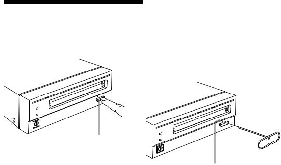
Eject the disk cartridge either by using software commands or by pressing the EJECT button.
EJECT button
Fig 3-3: Ejecting the Disk Cartridge Using the EJECT
button
1Turn off the disk unit if the power is still on.
2Insert the emergency eject tool (or a paper clip) straight into the emergency eject hole to trip the manual ejection mechanism.
Emergency eject Tool(supplied)
Insert into the emergency eject hole.
Note
Do not attempt to eject a disk cartridge while the BUSY indicator is lit orange (except when it is flashing at about 2-second intervals due to overheating). Ejecting the disk while it is being accessed may cause data write errors or may result in loss of data.
Also, it may take a few moments (up to 45 seconds) for the disk to eject when the write cache is enabled, because data in the cache must first be written to the disk.
■What to do if the disk does not eject
The disk cartridge may not come out, even when you press the EJECT button or use a software command, under the following conditions:
•The eject function has been disabled using the function switch or a software command;
•The host computer is not functioning properly;
•The disk unit has been turned off (due to a power failure, etc.); or
•Something is wrong with your disk unit itself.
When you cannot eject the disk cartridge using the EJECT button or software commands, remove it as follows.
Fig 3-4: Inserting the Emergency Eject Tool
This should cause the disk cartridge to eject.
Caution
The tip of the emergency eject tool is sharp. When handling the tool, please be careful to avoid injury.
14 Chapter 3 Using the Disk Unit
 Loading...