


 Loading...
VIDEO PROJECTOR
VPL-VW600ES
REMOTE COMMANDER
RM-PJ24
SERVICE MANUAL 1st Edition
!
! WARNING
This manual is intended for qualified service personnel only.
To reduce the risk of electric shock, fire or injury, do not perform any servicing other than that contained in the operating instructions unless you are qualified to do so. Refer all servicing to qualified service personnel.
! WARNUNG
Die Anleitung ist nur für qualifiziertes Fachpersonal bestimmt.
Alle Wartungsarbeiten dürfen nur von qualifiziertem Fachpersonal ausgeführt werden. Um die Gefahr eines elektrischen Schlages, Feuergefahr und Verletzungen zu vermeiden, sind bei Wartungsarbeiten strikt die Angaben in der Anleitung zu befolgen. Andere als die angegeben Wartungsarbeiten dürfen nur von Personen ausgeführt werden, die eine spezielle Befähigung dazu besitzen.
! AVERTISSEMENT
Ce manual est destiné uniquement aux personnes compétentes en charge de l’entretien. Afin de réduire les risques de décharge électrique, d’incendie ou de blessure n’effectuer que les réparations indiquées dans le mode d’emploi à moins d’être qualifié pour en effectuer d’autres. Pour toute réparation faire appel à une personne compétente uniquement.
き差しできるコンセントに電源プラグを接続してくだ さい。
WARNING
When installing the unit, incorporate a readily accessible disconnect device in the fixed wiring, or connect the power cord to a socket-outlet which must be provided near the unit and easily accessible, so that the user can turn off the power in case a fault should occur.
WARNUNG
Beim Einbau des Geräts ist daher im Festkabel ein leicht zugänglicher Unterbrecher einzufügen, oder das Netzkabel muß mit einer in der Nähe des Geräts befindlichen, leicht zugänglichen Wandsteckdose verbunden werden, damit sich bei
einer Funktionsstörung die Stromversorgung zum Gerät jederzeit unterbrechen läßt.
つ可能性があるコネクターを以下のポートに接続しない でください。
: LAN
For safety, do not connect the connector for peripheral device wiring that might have excessive voltage to the following port.
: LAN connector
Follow the instructions for the above port.
VPL-VW600ES

必ず指定の電池に交換してください。
処理してください。
CAUTION
Danger of explosion if battery is incorrectly replaced. Replace only with the same or equivalent type recommended by the manufacturer.
When you dispose of the battery, you must obey the law in the relative area or country.
ATTENTION
Il y a danger d’explosion s’il y a remplacement incorrect de la batterie. Remplacer uniquement avec une batterie du même type ou d’un type équivalent recommandé par le constructeur.
Lorsque vous mettez la batterie au rebut, vous devez respecter la législation en vigueur dans le pays ou la région où vous vous trouvez.
VORSICHT
Explosionsgefahr bei Verwendung falscher Batterien. Batterien nur durch den vom Hersteller empfohlenen oder einen gleichwertigen Typ ersetzen.
Wenn Sie die Batterie entsorgen, müssen Sie die Gesetze der jeweiligen Region und des jeweiligen Landes befolgen.
FÖRSIKTIGHET!
Fara för explosion vid felaktigt placerat batteri. Byt endast mot samma eller likvärdig typ av batteri, enligt tillverkarens rekommendationer.
När du kasserar batteriet ska du följa rådande lagar för regionen eller landet.
PAS PÅ
Fare for eksplosion, hvis batteriet ikke udskiftes korrekt.
Udskift kun med et batteri af samme eller tilsvarende type, som er anbefalet af fabrikanten.
Når du bortskaffer batteriet, skal du følge lovgivningen i det pågældende område eller land.
HUOMIO
Räjähdysvaara, jos akku vaihdetaan virheellisesti. Vaihda vain samanlaiseen tai vastaavantyyppiseen, valmistajan suosittelemaan akkuun.
Noudata akun hävittämisessä oman maasi tai alueesi lakeja.
FORSIKTIG
Eksplosjonsfare hvis feil type batteri settes i. Bytt ut kun med samme type eller tilsvarende anbefalt av produsenten.
Kasser batteriet i henhold til gjeldende avfallsregler.
VPL-VW600ES |
1 (P) |
Table of Contents
Manual Structure |
2. Electrical Adjustments |
Purpose of this manual............................................................ |
2 (E) |
Related manuals...................................................................... |
2 (E) |
1. |
Service Overview |
|
|
1-1. |
Appearance Figure .................................................... |
1-1 (E) |
|
1-2. |
Board Location.......................................................... |
1-1 (E) |
|
1-3. |
Tighten Torque .......................................................... |
1-2 (E) |
|
1-4. |
Disassembly .............................................................. |
1-3 (E) |
|
1-4-1. |
Top Cover Assembly/Rear Cover Assembly/ |
|
|
|
|
NR Board/HA Board/BT Board....................... |
1-3 (E) |
1-4-2. |
Front Panel Assembly/NF Board/HB Board... |
1-5 (E) |
|
1-4-3. |
U Board............................................................ |
1-6 (E) |
|
1-4-4. |
DC Fan (For Power Supply Assembly) ........... |
1-7 (E) |
|
1-4-5. |
CB Board/CA Board/Optical Unit Assembly... |
1-8 (E) |
|
1-4-6. |
DC Fan (For Lamp) ....................................... |
1-11 (E) |
|
1-4-7. |
DC Fan (For Intake)/M Board ....................... |
1-12 (E) |
|
1-4-8. |
DC Fan (For Lamp and Prism) ...................... |
1-13 (E) |
|
1-4-9. |
DC Fan (For Q Board)................................... |
1-14 (E) |
|
1-4-10. |
G Board.......................................................... |
1-15 (E) |
|
1-4-11. |
Q Board.......................................................... |
1-16 (E) |
|
1-5. |
Indicator Display..................................................... |
1-17 (E) |
|
1-6. |
Circuit Description .................................................. |
1-18 (E) |
|
1-6-1. |
Video Signal Processing System.................... |
1-18 (E) |
|
1-6-2. |
Signal Generation Board................................ |
1-18 (E) |
|
1-6-3. |
Sensor Board.................................................. |
1-18 (E) |
|
1-6-4. |
Power Supply Board ...................................... |
1-19 (E) |
|
1-7. Processing of Flexible Flat Cable with Connector and |
|||
|
Harness of Bottom Cover Assembly ....................... |
1-20 (E) |
|
1-7-1. |
Flexible Flat Cable with Connector............... |
1-20 (E) |
|
1-7-2. |
Harness........................................................... |
1-21 (E) |
|
1-8. |
Optional Fixtures..................................................... |
1-22 (E) |
|
1-8-1. |
Extension ...................................................... |
1-22 (E) |
|
1-8-2. |
Connection .................................................... |
1-22 (E) |
|
1-9. |
Lead-free Solder...................................................... |
1-23 (E) |
|
2-1. |
Preparations............................................................... |
2-1 (E) |
|
2-1-1. |
Required Equipment ........................................ |
2-1 (E) |
|
2-1-2. |
How to Enter the Service Mode....................... |
2-1 (E) |
|
2-1-3. |
How to Enter the Model Name Display |
|
|
|
|
(Shop Demonstration) Mode ........................... |
2-1 (E) |
2-2. |
Servicing Precautions................................................ |
2-2 (E) |
|
2-2-1. |
When Replacing the Optical Unit Assembly ... |
2-2 (E) |
|
2-2-2. |
When Replacing the QA Board ....................... |
2-2 (E) |
|
2-2-3. |
When Replacing the Board |
|
|
|
|
Other Than the Above...................................... |
2-2 (E) |
2-3. |
White Balance Adjustment........................................ |
2-3 (E) |
|
2-3-1. |
D93 Mode ........................................................ |
2-3 (E) |
|
2-3-2. |
D75 Mode ........................................................ |
2-3 (E) |
|
2-3-3. |
D65 Mode ........................................................ |
2-4 (E) |
|
2-3-4. |
D55 Mode ........................................................ |
2-4 (E) |
|
2-3-5. |
Custom Setting................................................. |
2-4 (E) |
|
2-4. Calibration "save enable" Execution Procedure........ |
2-4 (E) |
||
2-5. |
Device Adjustment Item Initialize Data.................... |
2-5 (E) |
|
3. |
Software Update |
|
3-1. |
Preparation ................................................................ |
3-1 (E) |
3-2. |
Firmware Update....................................................... |
3-2 (E) |
3-3. |
Writing of Adjustment Data ...................................... |
3-3 (E) |
3-4. |
Reading of Adjustment Data ..................................... |
3-3 (E) |
3-5. |
Writing of FLASH Data............................................ |
3-4 (E) |
4. |
Spare Parts |
|
4-1. |
Notes on Repair Parts...................................................... |
4-1 |
4-2. |
Exploded Views............................................................... |
4-2 |
4-3. |
Packing Materials & Supplied Accessories................... |
4-15 |
5. Diagrams
Overall ............................................................................ |
5-1 |
Frame Wiring................................................................... |
5-2 |
VPL-VW600ES |
1 (E) |

Manual Structure
Purpose of this manual
This manual is the Service Manual of the Video Projector VPL-VW600ES.
This manual contains the service overview, electrical adjustments, software update, spare parts, block diagrams, schematic diagrams, and board layouts.
The service of this unit is basically performed by the replacement of board. Therefore, the schematic diagram, board layout and electrical parts list are not contained.
Related manuals
In addition to this Service Manual, the following manuals are provided.
. Operating Instructions (Supplied with unit)
This manual is necessary for application and operation of this unit.
. Protocol Manual (Available on request)
This manual describes the protocol for controlling this unit.
2 (E) |
VPL-VW600ES |
Section 1
Service Overview
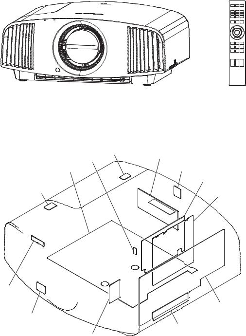
1-1. Appearance Figure
RM-PJ24
1-2. Board Location
|
|
BT |
Power supply unit |
|
CL |
|
|
|
|
|
|
Q |
|
|
NR |
CA
U
CB
HB
G
NF
HA
M
VPL-VW600ES |
1-1 (E) |
1-3. Tighten Torque
Tighten the each screw with the torque below. n
When using the torque driver with the notation of cN.m, interpret it as follows. Example: 0.8 N.m = 80 cN.m
. B2.6 x 6: 0.40 ?0.02 N.m (4.1 ?0.2 kgf.cm)
. B3 x 6: 0.60 ?0.02 N.m (6.1 ?0.2 kgf.cm)
. BTP2.6 x 8: 0.40 ?0.02 N.m (4.1 ?0.2 kgf.cm)
. BSW2 x 6: 0.18 ?0.02 N.m (1.8 ?0.2 kgf.cm)
. P2 x 4: 0.18 ?0.02 N.m (1.8 ?0.2 kgf.cm)
. PSW2 x 6: 0.18 ?0.02 N.m (1.8 ?0.2 kgf.cm)
. PSW2.6 x 6: 0.40 ?0.02 N.m (4.1 ?0.2 kgf.cm)
. PSW3 x 8: 0.60 ?0.02 N.m (6.1 ?0.2 kgf.cm)
1-2 (E) |
VPL-VW600ES |
1-4. Disassembly
n
Remove parts in the order of numbers shown in the figure, in this section.
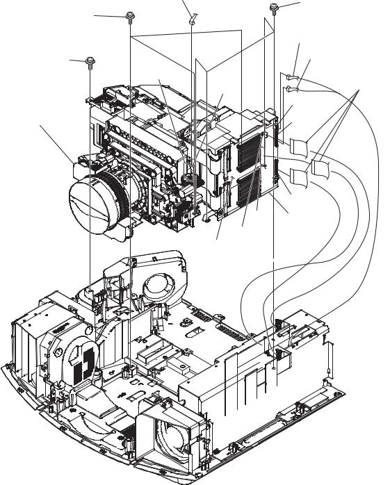
1-4-1. Top Cover Assembly/Rear Cover Assembly/NR Board/HA Board/BT Board
6 Top cover assembly
Six hooks
HA board
5 Harness |
CN60 |
1 Nine screws (BVTP3 x 12)
(BLACK)
1 Nine screws
(BVTP3 x 12) (BLACK)
4 Two screws (BVTP3 x 12) (SILVER)
Two hooks
3 Filter cover
2 Two screws (BVTP3 x 12) (BLACK)
Bottom side
VPL-VW600ES |
1-3 (E) |
@/ Top cover (LAMP)
CN002
@] Module board
!- Two harnesses
!; Button cover
CN61
CN62
!] HA board |
|
!\ HA button |

A
@- Three screws (BVTP3 x 12) (BLACK)
@= Cover (BT board)

 @[ BT board
CN003
@\ Harness
9 Harness
@, Top cover
!= Two hooks
!. Bracket (lid)
!, Sheet (TOP COVER)
!' Three screws (BVTP3 x 12)
(SILVER)
@; Four screws (BVTP3 x 12) (SILVER)
8 Rear cover assembly
0 NR board
CN35
7 Two screws (BVTP3 x 12) (SILVER)
1-4 (E) |
VPL-VW600ES |
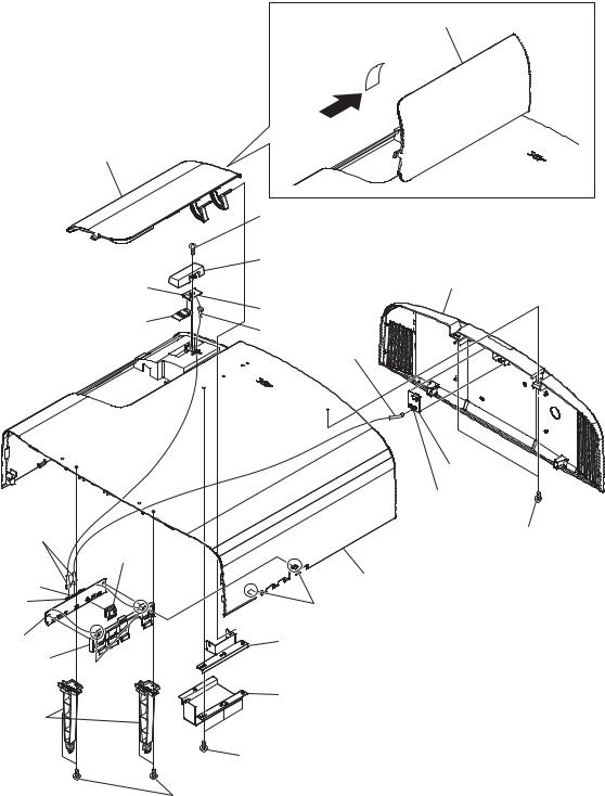
1-4-2. Front Panel Assembly/NF Board/HB Board
. Remove the top cover assembly and rear cover assembly. (Refer to Section 1-4-1.)
|
|
|
0 Harness |
|
|
|
!= HB board |
6 Harness |
|
1 Two screws |
|
|
||
CN50 |
|
|||
(BVTP3 x |
12) |
|
||
|
|
|
||
(SILVER) |
|
|
|
|
|
|
|
7 Screw |
4 Two screws |
!- Two hooks |
|
|
(BVTP3 x 6) |
(BVTP3 x 12) |
|
|
CN40 |
(SILVER) |
|
|
|
|
5 Fin |
|
|
|
|
|
|
|
|
|
9 NF board |
|
8 Hook |
|
|
|
|
|
|
|
3 Front panel assembly |
|
2 Four hooks
VPL-VW600ES |
1-5 (E) |
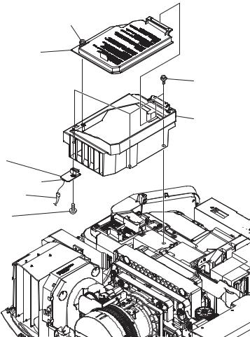
1-4-3. U Board
. Remove the top cover assembly and rear cover assembly. (Refer to Section 1-4-1.)
. Remove the front panel assembly. (Refer to Section 1-4-2.)
1 Loosen the screw (with drop-safe).
2 Lanp door
3 Three screws (PSW3 x 8)
4 Lamp house (UP) assembly
7 U board
CN20
5 Harness
6 Screw
(BVTP3 x 12)
1-6 (E) |
VPL-VW600ES |

1-4-4. DC Fan (For Power Supply Assembly)
. Remove the top cover assembly and rear cover assembly. (Refer to Section 1-4-1.)
. Remove the front panel assembly. (Refer to Section 1-4-2.)
. Remove the lamp house (UP). (Refer to Section 1-4-3.)
!= Ballast holder (A) assembly
!- Seven hooks
!; Power supply block
CN2
![ Two fan dampers
0 Ballast chassis |
CN1 |
!] DC fan |
|
!\ Two fan dampers |
|||
|
|||
|
|
||
|
|
!' Harness |
|
|
!, Harness |
|
|
!. Ballast holder (B) |
|
|
|
8 Six screws |
9 Power supply assembly |
||
(PSW3 x 8) |
|||
|
7 Ground terminal |
||
|
|
||
CN3 |
|
6 Three screws |
|
|
|
(PSW3 x 8) |
|
|
|
3 Harness |
|
5 Harness |
|
4 Relay connectors |
|
|
|
1 Three screws |
|
Power |
|
(PSW3 x 8) |
|
supply board |
|
||
|
|
2 G cover |
|
|
|
CN201 |
|
|
|
G board |
|
VPL-VW600ES |
1-7 (E) |
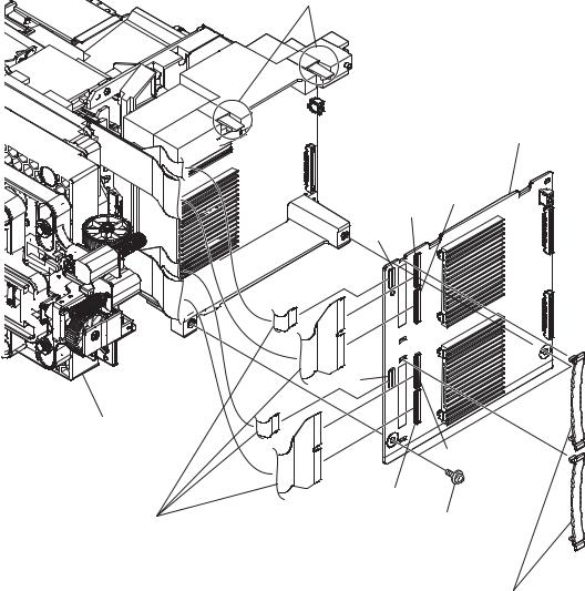
1-4-5. CB Board/CA Board/Optical Unit Assembly
. Remove the top cover assembly and rear cover assembly. (Refer to Section 1-4-1.)
. Remove the front panel assembly. (Refer to Section 1-4-2.)
. Remove the lamp house (UP). (Refer to Section 1-4-3.)
. Remove the power supply assembly. (Refer to Section 1-4-4.)
|
7 Harness |
3 Four screws |
|
|
|
2 Three screws |
|
(PSW3 x 8) |
|
|
|
(PSW4 x 12) |
|
|
|
|
5 Harness |
1 Screw |
|
6 Harness |
(PSW3 x 14) |
|
|
|
4 Three flexible |
|
CL board |
|
|
|
flat cables |
|
|
CN1006 |
with connector |
|
|
|
|
|
CN3000 |
8 Optical block |
|
CN4001 |
CN5001
CN2000 CB board
CN1000
CA board
1-8 (E) |
VPL-VW600ES |
!= Two hooks

!' Two hooks
!\ Two flexible wiring boards
!, CA board
CN2502
CN2500
CN2501
Optical block
!] Flat clamp (FCR-60)
!; Two crews (PSW3 x 8)
@= Optical unit assembly
@- Lens cap
!. Three screws (PSW3 x 8)
@/ Holder (C board)
1-10 (E) |
VPL-VW600ES |
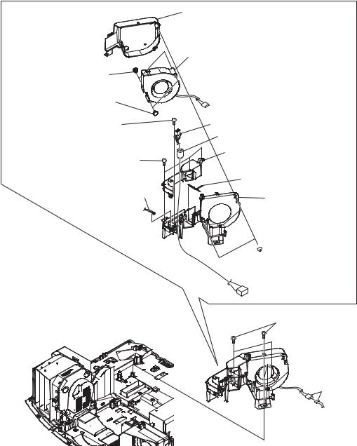
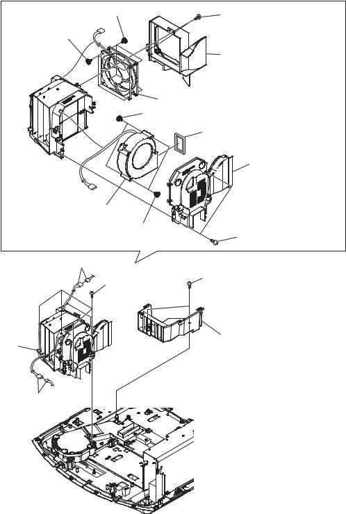
1-4-6. DC Fan (For Lamp)
. Remove the top cover assembly and rear cover assembly. (Refer to Section 1-4-1.)
. Remove the front panel assembly. (Refer to Section 1-4-2.)
. Remove the lamp house (UP). (Refer to Section 1-4-3.)
. Remove the power supply assembly. (Refer to Section 1-4-4.)
. Remove the optical block. (Refer to Section 1-4-5.)
!\ Two fan dampers
![ Two fan dampers
4Screw (BVTP3 x 12) (SILVER)
7 Three screws (BVTP3 x 12) (SILVER)
9 Fuse connector assembly
!; Lamp fan duct (bottom)
!] DC fan
5 Lamp connector assembly
6 Clamp filter
8 Lamp fan duct (cover) assembly
!= Baffle plate assembly
!- Lamp fan duct (base)

 0 Two screws (BVTP3 x 12) (SILVER)
2 Two screws (BVTP3 x 12) (SILVER)
 3 Lamp fan assembly
1 Relay
connector
VPL-VW600ES |
1-11 (E) |
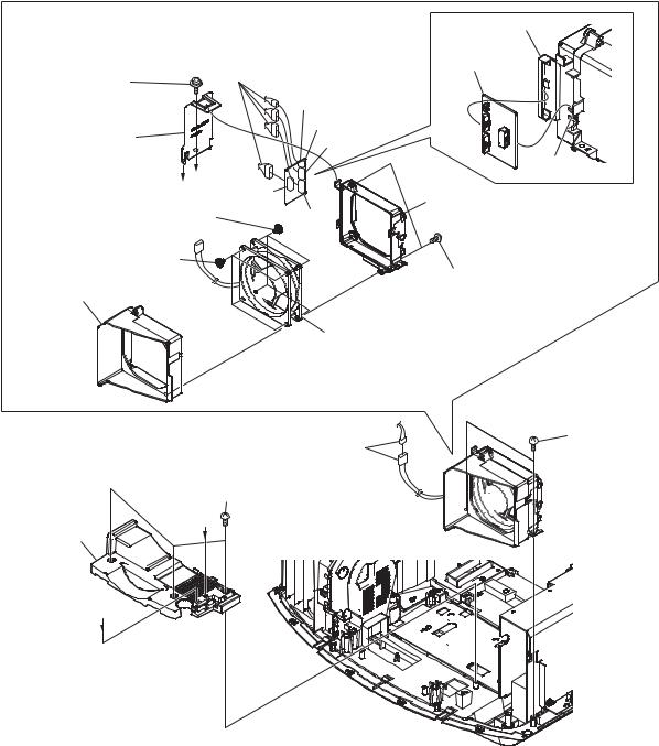
1-4-7. DC Fan (For Intake)/M Board
. Remove the top cover assembly and rear cover assembly. (Refer to Section 1-4-1.)
. Remove the front panel assembly. (Refer to Section 1-4-2.)
. Remove the lamp house (UP). (Refer to Section 1-4-3.)
. Remove the power supply assembly. (Refer to Section 1-4-4.)
. Remove the optical block. (Refer to Section 1-4-5.)
3 Screw |
5 Four harnesses |
|
|
||
(PTPWH3 x 8) |
7 M board |
|
|
||
4 M cover |
CN307 |
|
CN304 |
||
|
||
B |
|
|
A |
CN308 |
|
|
||
0 Four fan dampers |
CN303 |
!= Four fan dampers
![ Fan holder (FR)
!- DC fan
1 Relay connectors
!] Three screws (BVTP3 x 12) (BLACK)
B
!\ Intake cover
9 Fan holder (RE)
7 M board
6 Hook
9 Fan holder (RE)
8Screw (BVTP3 x 12) (SILVER)
2 Two screws (BVTP3 x 12) (SILVER)
A
1-12 (E) |
VPL-VW600ES |
1-4-8. DC Fan (For Lamp and Prism)
. Remove the top cover assembly and rear cover assembly. (Refer to Section 1-4-1.)
. Remove the front panel assembly. (Refer to Section 1-4-2.)
. Remove the lamp house (UP). (Refer to Section 1-4-3.)
. Remove the power supply assembly. (Refer to Section 1-4-4.)
. Remove the optical block. (Refer to Section 1-4-5.)
. Remove the DC fan (for lamp). (Refer to Section 1-4-6.)
. Remove the DC fan (for intake). (Refer to Section 1-4-7.)
9 Four fan dampers |
7 Two screws |
|
|
|
(BVTP3 x 12) |
!- Four fan dampers |
(SILVER) |
|
|
|
8 Fan bracket (FR) |
A
0 DC fan
!; Two fan dampers
!' Sirocco cushion
![ Fan bracket (SIDE)
!\ DC fan
!] Two fan dampers
!= Two screws (BVTP3 x 12) (SILVER)
4 Relay connectors |
1 Two screws |
|
|
(BVTP3 x 12) |
|
5 Four screws |
(SILVER) |
|
(BVTP3 x 12) |
|
|
(BLACK) |
|
|
6 Fan duct |
2 Lamp house (BTM) |
|
assembly |
||
|
3 Relay connectors
VPL-VW600ES |
1-13 (E) |
Loading...