


3-776-792-12(1)
Remote Control
Panel
Operating Instructions
Before operating the unit, please read this manual thoroughly and retain it for future reference.
RCP-D50/D51
2004 by Sony Corporation

WARNING
To prevent fire or shock hazard, do not expose the unit to rain or moisture.
To avoid electrical shock, do not open the cabinet. Refer servicing to qualified personnel only.
AVERTISSEMENT
Afin d’éviter tout risque d’incendie ou d’électrocution, ne pas exposer cet appareil à la pluie ou à l’humidité.
Afin d’écarter tout risque d’électrocution, garder le coffret fermé. Ne confier l’entretien de l’appareil qu’à un personnel qualifié.
WARNUNG
Um Feuergefahr und die Gefahr eines elektrischen Schlages zu vermeiden, darf das Gerät weder Regen noch Feuchtigkeit ausgesetzt werden.
Um einen elektrischen Schlag zu vermeiden, darf das Gehäuse nicht geöffnet werden. Überlassen Sie Wartungsarbeiten stets nur qualifiziertem Fachpersonal.
For the customers in the USA
This equipment has been tested and found to comply with the limits for a Class A digital device, pursuant to Part 15 of the FCC Rules. These limits are designed to provide reasonable protection against harmful interference when the equipment is operated in a commercial environment. This equipment generates, uses, and can radiate radio frequency energy and, if not installed and used in accordance with the instruction manual, may cause harmful interference to radio communications. Operation of this equipment in a residential area is likely to cause harmful interference in which case the user will be required to correct the interference at his own expense.
You are cautioned that any changes or modifications not expressly approved in this manual could void your authority to operate this equipment.
The shielded interface cable recommended in this manual must be used with this equipment in order to comply with the limits for a digital device pursuant to Subpart B of Part 15 of FCC Rules.
For the customers in Europe
This product with the CE marking complies with the EMC Directive (89/336/EEC) issued by the Commission of the European Community.
Compliance with this directive implies conformity to the following European standards:
•EN55103-1: Electromagnetic Interference (Emission)
•EN55103-2: Electromagnetic Susceptibility (Immunity) This product is intended for use in the following Electromagnetic Environment(s):
E1 (residential), E2 (commercial and light industrial), E3 (urban outdoors) and E4 (controlled EMC environment, ex. TV studio).
Pour les clients européens
Ce produit portant la marque CE est conforme à la Directive sur la compatibilité électromagnétique (EMC) (89/336/CEE) émise par la Commission de la Communauté Européenne.
La conformité à cette directive implique la conformité aux normes européennes suivantes:
•EN55103-1: Interférences électromagnétiques (émission)
•EN55103-2: Sensibilité électromagnétique (immunité) Ce produit est prévu pour être utilisé dans les environnements électromagnétiques suivants:
E1 (résidentiel), E2 (commercial et industrie légère),
E3 (urbain extérieur) et E4 (environnement EMC contrôlé, ex. studio de télévision).
Für Kunden in Europa
Dieses Produkt besitzt die CE-Kennzeichnung und erfüllt die EMV-Richtlinie (89/336/EWG) der EG-Kommission. Angewandte Normen:
•EN55103-1: Elektromagnetische Verträglichkeit (Störaussendung)
•EN55103-2: Elektromagnetische Verträglichkeit (Störfestigkeit),
für die folgenden elektromagnetischen Umgebungen:
E1 (Wohnbereich), E2 (kommerzieller und in beschränktem Maße industrieller Bereich), E3 (Stadtbereich im Freien) und E4 (kontrollierter EMV-Bereich, z.B. Fernsehstudio).
2

Table of Contents
Overview ............................................................................ |
4 |
Features ............................................................................... |
4 |
Locations and Functions of Parts ................................... |
5 |
Operation Panel ................................................................... |
5 |
Connector Panel ................................................................ |
13 |
Mounting on a Console .................................................. |
14 |
Menu Configuration and Basic Menu Operations ........ |
15 |
Basic Operating Procedure ................................................ |
15 |
Basic Configuration of Menu Display .............................. |
16 |
Menu Items with the DXC-D50-Series Cameras .............. |
20 |
Menu Items with the DXC-D30/D35-Series Cameras ...... |
27 |
Menu Items with the DXC-637-Series Cameras ............... |
34 |
Menu Items with the CCU-TX50 ...................................... |
38 |
Initial Settings.................................................................. |
45 |
Setting the Operating Conditions of the RCP-D50/D51 ... |
45 |
Setting the Built-in Clock .................................................. |
45 |
Adjusting the Buzzer Sound .............................................. |
46 |
Adjusting the Brightness of the LEDs............................... |
47 |
Changing the Functions of the Rotary Encoders ............... |
47 |
Adjusting the Brightness/Contrast of the LCD ................. |
48 |
Assigning a Function to the ASSIGN Button.................... |
48 |
Specifying the Security Codes .......................................... |
49 |
File Operations ................................................................ |
51 |
Operating Scene Files........................................................ |
53 |
Transferring Scene Files between the Camera and |
|
a Memory Stick (with the DXC-D50 Series) ............... |
54 |
Operating Setup Files (for DXC-D30/D35 Series only) ... |
55 |
Skin Detail Correction/Skin Matrix Adjustment |
|
(for DXC-D30/D35/D50 Series Only) ..................... |
56 |
Multi-Camera Control...................................................... |
57 |
Connections and Preparatons ............................................ |
57 |
Adjusting the Iris/Master Black of Multiple Cameras |
|
at One Time .................................................................. |
57 |
Data Transfer Among Multiple Cameras .......................... |
57 |
Operating Multiple Cameras from One RCP Unit — |
|
Command Link............................................................. |
58 |
Memory Sticks ................................................................. |
59 |
Using a Memory Stick....................................................... |
59 |
Notes on Memory Stick..................................................... |
59 |
Specifications .................................................................. |
61 |
3

Overview
The RCP-D50/D51 Remote Control Panel enables remote operation of the DXC-D50-series, DXC-D30/ D35-series,or DXC-637-series Color Video Cameras.
The RCP-D50 and RCP-D51 are completely identical in their functions except with respect to the iris and master black adjustments.
For the iris and master black adjustments, the RCPD50 uses a joystick type control while the RCP-D51 uses rotary knobs.
Features
Optimal control parts arrangement for basic camera operation
This remote control panel is provided with essential control functions for basic operation of a camera. The buttons, knobs, and other controls have been arranged according to their functions and with
consideration to their frequency of use. Indicators and buttons light or flash to indicate the status of the system operation. Also, guard frames are provided to protect against accidental use of those buttons vital to camera operation. These features ensure easy and error-free use of this remote control panel.
Full control of shooting operations
Besides controlling camera adjustments and settings, this unit can control tripod operations (pan and tilt) and lens settings (focus and zoom).
Scene file
The unit provides memory to hold data on shooting conditions for 20 different scenes, to enable easy readjustment of the camera for any memorized scenes. (When a DXC-D50-series camera is connected, data are held in memory of the camera.)
Coordination of settings among several cameras
In a system that includes several cameras that are connected via CCUs, connecting the CCUs allows this unit to set up all of the cameras into the same color condition.
Confirmation of camera conditions and operation status
This unit’s LCD panel indicates camera conditions such as the optical filter position, value, and lens extender setting. The results of the camera’s selfdiagnosis tests are also displayed on the LCD panel.
Signal transmission via a digital line
Between this remote control panel and the camera control unit, signals are digitally transmitted via a single connection cable (CCA-7), ensuring a reliable signal. Operating power is also supplied via the cable.
Memory Stick slot
Various data, including scene files, can be stored on a Memory Stick and reproduced at any time.
Touch panel with 31/2-inch LCD for various operations
The control panel has a touch panel that permits various items to be selected and adjusted on the LCD in menu format. (The menu items differ among the cameras to be connected.)
Video display function
The LCD can also display pictures from the connected camera, permitting you to use it as a convenient video monitor.
Four units mountable on a 19-inch rack
Up to four units of this control panel can be mounted in a line on a 19-inch EIA standard rack.
4

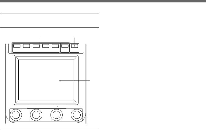
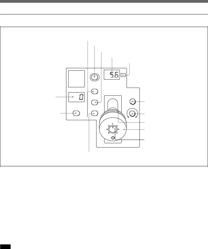
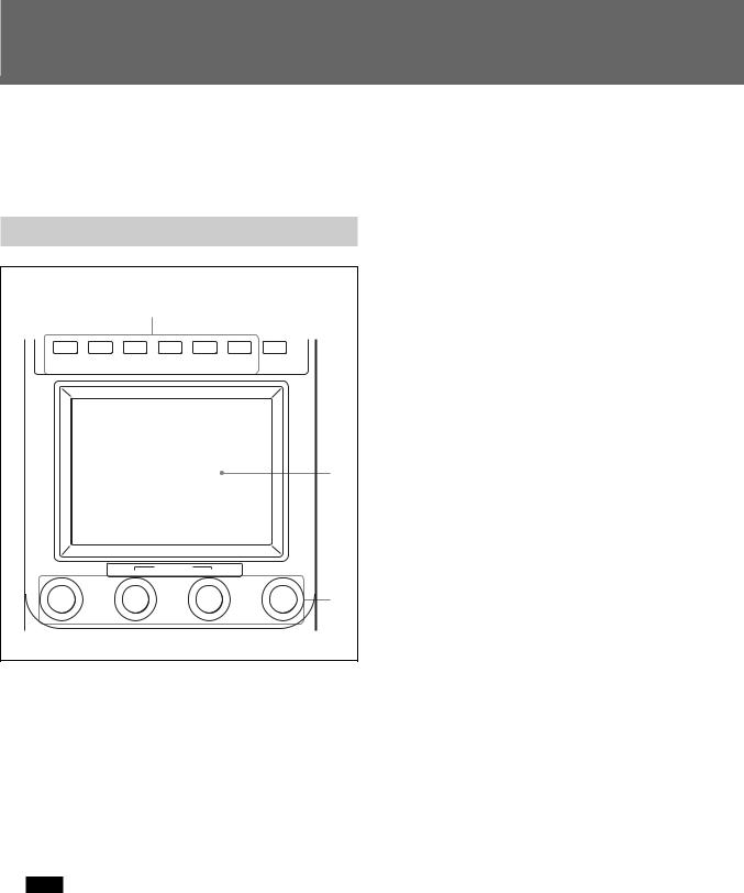
Locations and Functions of Parts
Operation Panel
1MASTER and SLAVE buttons
2PREVIEW button
3STANDARD button
MASTER |
SLAVE ASSIGN CAM PW |
BARS |
CLOSE |
|
AUTO SETUP |
|
|
STANDARD |
PREVIEW SKIN DTL LEVEL |
START |
BLACK |
SET UP |
WHITE |
||
qaASSIGN button
qsPower and output select buttons qdAUTO SETUP buttons
4Camera/CCU function ON/OFF buttons
5600K AUTO |
SKIN |
DETAIL PRESET |
A |
B |
KNEE |
DETAIL |
GATE |
WHITE |
|
PAINT1 PAINT2 PAINT3 SCENE OTHERS FUNCTION MONITOR MENU
qfWhite balance control buttons
Menu operation block (page 9)
MONITOR
BRIGHT |
CONTRAST |
5WHITE knobs
WHITE |
MASTER |
DETAIL |
GAMMA |
|
6BLACK/FLARE knobs and
indicator |
|
BLACK/FLARE a |
|
|
|
|
EXT |
7Camera number/tally indication |
|
IRIS/M.BLACK |
|
window |
|
|
|
|
ACTIVE |
|
|
|
|
IRIS/M.BLACK |
OPEN |
|
|
|
|
|
|
LINK |
|
|
MASTER |
AUTO |
SENS |
|
BLACK |
||
|
|
||
|
RELATIVE |
RELATIVE |
CLOSE OPEN |
|
|
|
|
8ALARM indicator |
|
|
COARSE |
ALARM CALL |
|
||
9CALL button |
|
||
|
|
|
|
0PANEL ACTIVE button |
PANEL |
|
|
ACTIVE |
|
|
|
CLOSE IRIS
REMOTE CONTROL PANEL
BLACK/FLARE a
7Camera number/tally indication |
|
|
EXT |
window |
|
|
|
|
|
|
|
|
MASTER |
|
|
|
BLACK |
RELATIVE IRIS/ |
SENS CLOSE OPEN |
|
|
M.BLACK |
COARSE |
|
|
LINK |
|
|
IRIS/M.BLACK AUTO |
|
|
|
ACTIVE |
|
|
8ALARM indicator |
|
|
|
9CALL button |
ALARM CALL |
|
|
|
|
|
|
0PANEL ACTIVE button |
PANEL |
|
|
ACTIVE |
|
|
|
IRIS
REMOTE CONTROL PANEL
qgMASTER GAMMA knob qhDETAIL knob
qjMEMORY STICK slot and access lamp
Iris/master black control block (page 10)
RCP-D50
Iris/master black control block (page 12)
RCP-D51
5
Locations and Functions of Parts
1 MASTER and SLAVE buttons
When adjusting the white balance of multiple cameras in Master/Slave mode, designate the master camera or the slave cameras. Press and light up the MASTER button to specify the connected camera for the master. Press and light up the SLAVE button to specify the connected camera for the slave. The slave cameras follow the master camera settings.
If you press a button when lit, it goes dark.
2 PREVIEW button
Press this button to control an external device connected to the EXT I/O connector on the connector panel.
For the operational specifications, see “3 EXT I/O (external input/output) connector (9-pin)” in “Connector Panel” on page 13.
3 STANDARD button
When you press this button, the video camera is initialized to its standard state and the button lights for several seconds.
If you press the button while it lights, the video camera retrieves the state before the button was lit.
4 Camera/CCU function ON/OFF buttons
Various functions of the video camera or the CCU can be turned on and off from this panel.
5600K AUTO |
SKIN |
DETAIL |
KNEE |
DETAIL |
GATE |
5600K (valid only with the DXC-D50 series):
5600K electric color temperature conversion function
AUTO KNEE: Auto knee function. When this button is lit (ON), the knee point is automatically adjusted according to the light content of the picture.
SKIN DETAIL: Skin detail function
DETAIL GATE: Skin detail gate function. When this button is lit (ON), the adjustment range of the skin tone detail is displayed in white on the monitor screen.
For details on the Skin detail and Skin detail gate, see “Skin Detail Correction/Skin Matrix Adjustment (for DXC-D30/ D35/D50-Series Only)” on page 56.
5 WHITE (white balance manual adjustment) knobs
Used to manually adjust the white balance.
The left knob is for the R signal and the right knob for the B signal.
6BLACK/FLARE (black balance/flare balance manual adjustment) knobs and indicator
Used to manually adjust the black balance (when the indicator is not lit) or the flare balance (when the indicator is lit).
From the left, the knobs are for R, G, and B signal adjustment.
Selection between black balance and flare balance is made using the OTHERS menu.
See “Changing the Functions of the Rotary Encoders” on page 47.
7 Camera number/tally indication window
The number of the camera being controlled from this panel is displayed in orange.
When a red tally signal is sent to the camera, the number is displayed in black and the background of the number lights in red.
When a green tally signal is sent to the camera, the number is displayed in black and the background of the number lights in green.
When both the red and green tally signals are simultaneously sent, the left half of the background lights in red and the right half lights in green.
8 ALARM indicator
Lights when trouble occurs in the camera system and the self-diagnostic function activates at the video camera or the CCU.
9 CALL button
When the camera is connected via a CCU, press to send a call signal to the video camera, on which the CALL button lights. The tally lamps on the camera and the red tally lamp on the CCU light when not lit, or go dark when lit.
When the CALL button on the video camera is pressed, the CALL button on this panel lights and a buzzer sounds.
6
0 PANEL ACTIVE button
Press and light up the button to permit this panel to control the camera system (Panel active status). The IRIS/M.BLACK ACTIVE button of the iris/ master black control block also lights.
If you press this button so that it goes dark, the panel will be locked, preventing accidental misoperation. If Panel Active Lock with a security code has been enabled, the PANEL ACTIVE and the IRIS/ M.BLACK ACTIVE buttons are locked by pressing the PANEL ACTIVE button for more than 2 seconds in Panel active status.
For details on Panel Active Lock, see “Specifying the Security Codes” on page 49.
qa ASSIGN button
Various functions can be assigned to this button using “SW Setting” of the RCP Config menu (No function is assigned at the factory).
To assign a function, see “Assigning a Function to the ASSIGN Button” on page 48.
qs Power and output select buttons
A B C
CAM PW |
BARS CLOSE |
ACAM PW (camera power) button
When the unit is connected to the CCU-TX7, you can turn the power supply to the video camera ON by pressing and lighting up this button. (The button promptly flashes until the camera becomes ready for transmission.)
When you press this button again, it starts flashing and the power supply is turned off.
BBARS (color-bar signal) button
Press and light up this button to activate the color-bar signal generator of the video camera and send the respective the color-bar signal. When you press this button again, the button goes dark and the camera picture is displayed.
CCLOSE button
Press and light the button to close the iris. To release the close mode, press the button again so that it goes dark.
The close mode is also released when you press the STANDARD or IRIS/M.BLACK LINK button, or operate a scene file.
qd AUTO SETUP buttons
A B C D
AUTO SETUP
SKIN DTL LEVEL START |
WHITE BLACK |
|
SET UP |
||
|
AAuto adjustment item select buttons
Press and light up these buttons to select the items to be automatically adjusted.
SKIN DTL SETUP: Skin detail
LEVEL: Gamma balance, knee point, master black level, etc.
For details on the Skin detail setup, see “Skin Detail Correction/Skin Matrix Adjustment (for DXC-D30/D35/D50 Series Only)” on page 56.
BSTART button
Press to start automatic adjustment of the selected items.
The button lights during adjustment and goes dark when adjustment is completed.
CWHITE (white balance) button
Press to automatically adjust the white balance. The button lights during adjustment and goes dark when adjustment is completed.
DBLACK (black balance) button
Press to automatically adjust the black balance and black set.
The button lights during adjustment and goes dark when adjustment is completed.
Note
If an error occurs during adjustment, the pressed button flashes.
7
Locations and Functions of Parts
qf White balance control buttons
PRESET |
A |
B |
|
WHITE |
|
PRESET: Press and light this button to retrieve the preset white balance of the camera.
A (memory A): Press and light this button to retrieve the white balance stored in memory A of the camera.
B (memory B) (valid only with the DXC-D50 series): Press and light this button to retrieve the white balance stored in memory B of the camera.
Note
When the ATW (automatic tracing white balance) function is active, the white balance control buttons are not operative.
qg MASTER GAMMA knob
Used to adjust the master gamma.
qh DETAIL knob
Used to adjust the detail level.
qj MEMORY STICK slot and access lamp
Insert a Memory Stick to store setting data, such as reference files and scene files of the video camera or CCU.
The access lamp shows the status of the Memory Stick.
Off: No Memory Stick is inserted.
Lit in green: There is a Memory Stick in the slot. In this condition, you can safely eject the Memory Stick.
Lit in red: Data are being read/written. If you eject the Memory Stick in this condition, the data are not guaranteed. All the data may be lost.
Note
If “Check Memory Stick” is displayed on the LCD in the menu operation block, check that the Memory Stick has sufficient unused storage space or it has been properly formatted.
For details on Memory Sticks, see page 59.
8
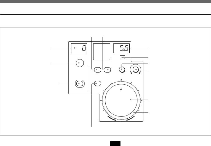
Menu operation block
|
|
1 |
2 |
|
PAINT 1 |
PAINT 2 |
PAINT 3 |
SCENE |
OTHERS FUNCTION MONITOR |
|
|
MENU |
|
|
|
|
|
|
3 |
|
|
BRIGHT |
MONITOR |
CONTRAST |
|
|
|
||
|
|
|
|
4 |
1 MENU buttons
Select the menu mode.
If you press and light one of these buttons, the menu for the selected mode appears on the LCD.
PAINT 1/2/3: Each selects the Paint menu to adjust various paint items, such as white, black, and flare. The configuration of the Paint menu depends on the connected camera. When Paint 4 and Paint 5 are available, you can select them by pressing v or V on the Paint menu display (see page 16) or the PAINT 3 button.
SCENE: Selects the File operation menu to register and retrieve scene files.
OTHERS: Selects the OTHERS menu to set various settings, such as operational conditions of this control panel.
FUNCTION: Selects the Function menu to control various camera and CCU functions.
For the items of each menu, see “Menu Configuration and Basic Menu Operations” on page 15.
2 MONITOR button
Press this button to display the picture from the connected camera on the LCD.
Press the button again to return to the display of this unit.
With a DXC-D50-series camera connected, eath time you press the MONITOR button, the camera picture, the camera picture with characters superimposed, and the menu display of this unit are displayed in sequence (When a CCU is used, the camera picture with characters is not displayed).
If no camera picture is displayed with the CCU-TX7 connected, consult your Sony dealer.
3 LCD/touch panel
Normally displays the statuses (see page 16).
When you press a MENU button, the corresponding menu is displayed to enable you to adjust the displayed items.
When you press the MONITOR button, the picture from the camera is displayed.
4 Control knobs (rotary encoders)
In Menu mode, adjust the selected items on the touch panel.
When the picture from the camera is displayed on the LCD (MONITOR button lit), you can adjust the picture brightness with the second knob (BRIGHT) from the left and the picture contrast with the third knob (CONTRAST) from the left.
9
Locations and Functions of Parts
Iris/master black control block (RCP-D50)
3IRIS/M.BLACK LINK button
|
4IRIS/M.BLACK ACTIVE button |
|
|
5AUTO button |
|
|
6f-number display |
|
|
7EXT indicator |
|
|
EXT |
|
|
IRIS/M.BLACK |
|
|
ACTIVE |
|
|
OPEN |
|
1MASTER BLACK display |
IRIS/M.BLACK |
|
LINK |
||
|
||
|
8SENS control knob |
|
|
MASTER |
BLACK AUTO SENS
2MASTER BLACK RELATIVE |
|
|
|
9COARSE control knob |
button |
RELATIVE |
RELATIVE |
CLOSE OPEN |
|
|
|
|||
|
|
|
COARSE |
0Master black control ring |
|
qaIRIS control lever |
|
qsPreview switch |
CLOSE |
IRIS |
|
|
qdIRIS RELATIVE button |
|
1 MASTER BLACK display
Displays the current master black setting in the range from –99 to +99.
2 MASTER BLACK RELATIVE button
When the IRIS/M.BLACK ACTIVE button is lit, the master black adjustment mode can be selected with this button.
Press and light up the button for Relative mode, or press and turn it dark for Absolute mode.
When the IRIS/M.BLACK ACTIVE button is not lit, Relative mode is automatically selected and this button is not operative.
Note
When VR STD MODE is set to Absolute with the VR Setting of the RCP Config menu, Relative mode is not selected even if you turn the IRIS/M.BLACK ACTIVE button off. When you turn the IRIS/ M.BLACK ACTIVE button on, the master black value corresponding to the position of the master black control ring is restored.
3IRIS/M.BLACK LINK (iris/master black adjustment link) button
Press and light up the button to perform linked adjustments of iris and master black for several cameras.
For details, see “Adjusting the Iris/Master Black of Multiple Cameras at One Time” on page 57.
4IRIS/M.BLACK ACTIVE (iris/master black active) button
Press and light up this button to enable the iris/master black control block of the panel.
When the PANEL ACTIVE button is pressed, this button also lights.
If you press this button so that it goes dark, the panel will be locked, preventing accidental misoperation.
10
5 AUTO button
Press and light the button to automatically adjust the iris according to the amount of input light.
When this button is lit, the reference value for automatic iris adjustment can be set with the iris control.
If you press the button when lit, it goes dark and manual iris adjustment is enabled.
6 f-number display
Displays the f number of the current iris setting. When the iris is closed, “CL” is displayed.
When the DXC-D50 series is connected, “OP” is displayed for the maximum f-number value.
7 EXT (lens extender) indicator
Lights when the lens extender is used.
8 SENS (sensitivity) control knob
Used for manual iris adjustment in Absolute mode. This control is not operative when Relative mode is selected.
See the table “Iris adjustment functions”to the right.
9 COARSE control knob
Used for manual iris adjustment.
See the table “Iris adjustment functions”to the right.
0 Master black control ring
Turn to manually adjust the master black level.
qa IRIS control lever
When the AUTO button is not lit, you can adjust the iris manually by moving the lever.
When the AUTO button is lit, the reference value for automatic iris adjustment can be set.
See the table “Iris adjustment functions” to the right.
qs Preview switch
Press this switch to control an external device connected to the EXT I/O connector on the connector panel.
For the operational specifications, see “3 EXT I/O (external input/output) connector (9-pin)” in “Connector Panel” on page 13.
qd IRIS RELATIVE (iris relative) button
When the IRIS/M.BLACK ACTIVE button is lit, the iris adjustment mode can be selected with this button. Press and light up the button for Relative mode or press so that it goes dark for Absolute mode.
When the IRIS/M.BLACK ACTIVE button is not lit, Relative mode is automatically selected and this button is not operative.
Note
When VR STD MODE is set to Absolute with “VR Setting” of the RCP Config menu, Relative mode is not selected even if you turn the IRIS/M.BLACK ACTIVE button off. When you turn the IRIS/ M.BLACK ACTIVE button on, the iris setting corresponding to the IRIS lever position is restored.
Iris adjustment functions
|
Relative mode |
Absolute mode |
|
(RELATIVE button lit) |
(RELATIVE button not lit) |
|
|
|
IRIS lever |
Adjusts the iris with |
Adjusts the iris |
(RCP-D50)/ |
relative values from |
within the variable |
IRIS control |
OPEN to CLOSED.a) |
range set by the |
(RCP-D51) |
|
SENS and COARSE |
|
|
controls. |
|
|
|
COARSE |
Adjusts the total |
Sets the lower limit |
control |
range from OPEN |
for CLOSED. |
|
to CLOSED in relative |
|
|
values. |
|
|
|
|
SENS |
Does not function. |
Sets the upper limit |
control |
|
for OPEN according |
|
|
to CLOSED value |
|
|
set by the COARSE |
|
|
control. |
|
|
|
a)The adjustable range can be set with “VR Rel. Scale” of the RCP Config menu.
11
Locations and Functions of Parts
Iris/master black control block (RCP-D51)
4IRIS RELATIVE button 5IRIS/M.BLACK LINK button
1MASTER BLACK display |
|
|
6f-number display |
|
|
EXT |
7EXT indicator |
2MASTER BLACK control |
|
|
8SENS control knob |
MASTER |
|
|
9COARSE control knob |
BLACK |
RELATIVE IRIS/ |
SENS |
CLOSE OPEN |
|
|||
|
M.BLACK |
|
COARSE |
|
LINK |
|
|
3IRIS/M.BLACK ACTIVE button |
|
|
|
IRIS/M.BLACK |
AUTO |
|
|
ACTIVE |
|
|
|
|
|
|
0IRIS control |
|
|
|
qaIris gauge |
|
|
|
IRIS |
|
qsAUTO button |
|
|
1 MASTER BLACK display
Displays the current master black setting in the range from –99 to +99.
2 MASTER BLACK control
Manually adjust the master black level.
The setting is displayed in the MASTER BLACK display.
3 IRIS/M.BLACK ACTIVE (iris/master black active) button
Press and light up this button to enable the iris/master black control block of the panel.
When the PANEL ACTIVE button is pressed, this button also lights.
If you press this button so that it goes dark, the panel will be locked, preventing accidental misoperation.
4 IRIS RELATIVE (iris relative) button
When the IRIS/M.BLACK ACTIVE button is lit, the iris adjustment mode can be selected with this button. Press and light up the button for Relative mode or press so that it goes dark for Absolute mode.
When the IRIS/M.BLACK ACTIVE button is not lit, Relative mode is automatically selected and this button is not operative.
Note
When VR STD MODE is set to Absolute with “VR Setting” of the RCP Config menu, Relative mode is not selected even if you turn the IRIS/M.BLACK ACTIVE button off. When you turn the IRIS/ M.BLACK ACTIVE button on, the iris setting corresponding to the position of the IRIS control is restored.
5IRIS/M.BLACK LINK (iris/master black adjustment link) button
Press and light up the button to perform linked adjustments of iris and master black for several cameras.
For details, see “Adjusting the Iris/Master Black of Multiple Cameras at One Time” on page 57.
6 f-number display
Displays the f number of the current iris setting. When the iris is closed, “CL” is displayed.
When the DXC-D50 series is connected, “OP” is displayed for the maximum f-number value.
7 EXT (lens extender) indicator
Lights when the lens extender is used.
12
8 SENS (sensitivity) control knob
Used for manual iris adjustment in Absolute mode. This control is not operative when Relative mode is selected.
See the table “Iris adjustment functions”on page 11.
9 COARSE control knob
Used for manual iris adjustment.
See the table “Iris adjustment functions” on page 11.
0 IRIS control
When the AUTO button is not lit, you can adjust the iris manually by turning the control.
When the AUTO button is lit, the reference value for automatic iris adjustment can be set with this control.
See the table “Iris adjustment functions” on page 11.
qa Iris gauge
Turn the gauge to set the line to the most frequently used iris position, and it can be used as the reference for manual iris adjustment.
qs AUTO button
Press and light the button to automatically adjust the iris according to the amount of input light.
When this button is lit, the reference value for automatic iris adjustment can be set with the iris control.
If you press the button when lit, it goes dark and manual iris adjustment is enabled.
Connector Panel
1MONITOR connector
2CCU/CAMERA connector
3EXT I/O connector
MONITOR |
CCU/ |
EXT I/O |
|
CAMERA |
|
1 MONITOR connector (BNC type)
Connect to a video monitor.
2CCU/CAMERA (camera control unit/camera) connector (10-pin)
Connect to the REMOTE connector of a camera control unit or a camera.
3EXT I/O (external input/output) connector (9-pin)
This connector permits you to control an external device using the PREVIEW button (page 6) or the preview switch (page 11).
Operational specifications
While the PREVIEW button or the preview switch (RCP-D50 only) is held pressed, pin 1 and pin 2 of the EXT I/O connector are short-circuited.
Pin assignment of the EXT I/O connector
5 1
9 6
Caution
When installing this panel, provide a gap of 7 cm (3 inches) or more behind the connector panel to prevent damage to cables.
13
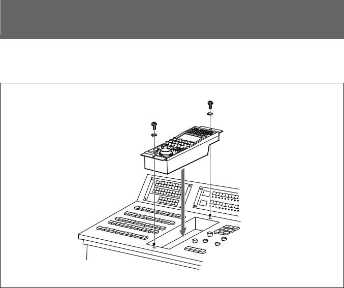
Mounting on a Console
The RCP-D50/D51 can be mounted on a console as shown below:
14
Menu Configuration and Basic Menu Operations
The RCP-D50/D51 provides menu operations for various functions such as adjustments of system equipment.
When the selected menu is composed of multiple pages
With the menu that is composed of multiple pages such as Paint menu, press v or V to flip the pages.
See “Initial display (Paint menu)” on the next page.
Basic Operating Procedure
|
|
1 |
|
|
PAINT 1 |
PAINT 2 |
PAINT 3 |
SCENE |
OTHERS FUNCTION MONITOR |
|
|
MENU |
|
|
|
|
|
|
2 |
|
|
|
MONITOR |
|
|
|
BRIGHT |
|
CONTRAST |
|
|
|
|
3 |
1 To display a menu, press and light one of the MENU buttons.
The menu operation mode is initiated and the menu for the pressed button appears on the display.
PAINT 1/2/3: Paint menu
SCENE: Scene file operation menu OTHERS: OTHERS menu FUNCTION: Function menu
Note
The menu items to be displayed depends on the connected camera.
2 Select the item to be adjusted.
Press the button that shows the name of the item on the menu to obtain the corresponding adjustment display or operation area.
When a submenu is shown
Press the desired submenu item to change the display.
See “Submenu” on page 17.
3 Set or adjust the item (parameters).
•Turn the control knobs (or press the button) to adjust (or set) the corresponding item (parameters) to the desired values.
See “Adjustment display” on page 17.
•When a message is displayed, follow the instruction and press [OK].
When the adjustment is finished
•To adjust another item of the same menu, press the names of that item.
•To adjust items of another menu, press the corresponding MENU button.
•To release the menu operation mode, press the lit MENU button.
•You may select Function menu without exiting the currently selected menu. When you exit Function menu by either of the following methods, the previous menu is restored.
–Press the lit FUNCTION button so that it goes dark.
–Press the lit MENU button for the previous menu.
To monitor the camera picture
Press the MONITOR button.
The picture from the connected camera is displayed on the LCD.
With a DXC-D50-series camera connected, eath time you press the MONITOR button, the camera picture, the camera picture with characters superimposed, and the menu display of this unit are displayed in sequence. (When a CCU is used, the camera picture with characters is not displayed.)
15

Menu Configuration and Basic Menu Operations
Basic Configuration of Menu Display
Status display
When you do not select any menu or the signal from the camera, the LCD shows the following status display:
On the status display, the set value of each item is only displayed. The setting is made with the Function menu or with the corresponding knob on the operation panel.
The set values of the shutter and master gain are displayed. You may adjust these items using the Function menu.
|
|
The ND filter number being selected |
Status |
|
on the camera is displayed. |
|
|
|
Shutter |
M. Gain |
Filter |
60 |
12dB |
1 |
When you select a scene file, |
Scene File : 2 DXC-D50 |
|
|
the filename is displayed. |
White |
Gamma |
Detail |
0 |
0 |
0 |
0 |
|
Black |
|
Iris |
0 |
0 |
0 |
2 |
You may adjust these items using the WHITE, MASTER GAMMA, BLACK/ FLARE, and DETAIL knobs, and IRIS control (or IRIS lever).
The “Black” columns can be changed to “Flare” using the OTHERS menu.
Initial display (Paint menu)
When you press and light the PAINT 1 (or PAINT 2, PAINT 3) button of the menu operation block, the initial display of the Paint menu is obtained.
To clear the adjusted values
The names of the items are displayed. Press the name of the item to be adjusted.
The color of the pressed name area will change, and the lower half of the panel will become the adjustment display (see the next page).
|
|
|
Current page number / total number of pages |
|
Clear |
|
|
1 / 5 |
Press either to flip the pages of the |
White |
Black |
Flare |
Gamma |
menu. |
/Knee |
|
|||
|
|
|
|
|
16
Adjustment display (Paint menu)
When you select an item on the initial display of the Paint menu, the lower half of the panel becomes the adjustment display for the selected item.
Example: when you select “White” from the PAINT 1 initial display with the DXC-D50 series connected
When you press this, the upper half of the panel becomes the monitor output setting display  (see page 19).
The adjustment parameters
for the selected item and their  adjustment values are
displayed.
You may adjust these items using the corresponding control knobs.
If you press a value area after pressing [Clear], that adjustment value is initialized to standard.
Clear |
|
1 / 5 |
|
White |
Black |
Flare Gamma |
|
|
|
/Knee |
|
Monitor |
|
White |
|
Select |
|
|
|
Preset |
Memory |
Memory |
ATW |
|
A |
B |
|
R |
B |
|
|
0 0
The name of the item selected on the initial display is displayed.
If you press this area after pressing [Clear], all the adjustment values for the selected item are initialized to standard.
 When there are any ON/OFF functions related to the adjustment, the names of the functions are displayed on this line.
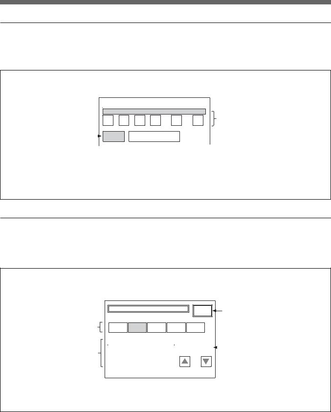
Submenu
If the selected item has many parameters, a submenu is displayed.
Example: when you select “Skin Detail” from the PAINT 2 initial display (Advance mode) with the DXC-D50 series connected
Clear |
|
2 / 5 |
|
|
|
Detail |
Skin |
Black |
|
Detail |
Gamma |
WF/PIX |
Detail 1 |
|
Select |
|
|
Submenu |
1 |
2 |
Level |
H/V Ratio |
Frequency |
0 |
0 |
0 |
Press to switch the parameters.
WF/PIX |
Detail 2 |
Select |
|
1 2
Crispening Level Dep
0 0
17

Menu Configuration and Basic Menu Operations
Function menu displays
When you press and light the FUNCTION button of the menu operation block, the scene file operation menu display is obtained.
When “Operation” is selected
Example: with the DXC-D50 series connected
Press one of these buttons calls the adjustment display of the corresponding paint item. The items to be displayed on this Function menu can be changed using the OTHERS menu. (You cannot jump to the items that are not available on the connected camera or disabled.)
Opera- |
SW |
Lens |
Filter |
tion |
|
/Pan |
1 |
White |
Black |
Flare |
Monitor |
|
|
|
Select |
Gamma |
Detail |
Skin |
Matrix |
/Knee |
|
Detail |
|
Shutter |
CLS |
TLCS |
Master |
|
|
|
Gain |
60 |
50.31 |
|
0dB |
You may adjust these items using the corresponding control knobs.
The ND filter number being selected on the camera is displayed.
When you press this, the upper half of the panel becomes the monitor output setting display (see the next page).
When “SW” is selected
Example: with the DXC-D35 series connected
Opera- |
SW |
Lens |
tion |
|
/Pan |
|
Skin |
Skin |
|
Detail |
Gate |
ATW |
TLCS |
Auto |
|
|
Knee |
|
Skin |
Flare |
|
Matrix |
Off |
Filter |
Current page number / |
1 |
total number of pages |
|
1 / 2
Press either to flip the pages of the menu.
These buttons turn on and off the corresponding functions.
Any button whose designation includes “Off” turns the respective function OFF when you light it. Other buttons turn the respective functions ON when you light them.
18
Monitor output set display (Expansion menu)
When you press [Monitor Select] on an adjustment display of the Paint menu, the upper half of the panel becomes the monitor output setting display.
|
|
|
|
|
|
|
|
|
|
|
|
|
|
|
|
|
|
|
When the CCU-TX7 is connected, you |
|
|
|
|
|
|
|
|
|
|
|
|
|
|
|
|
|
|
|
can select the WF/PIX output signals. |
|
|
|
|
|
|
|
|
|
|
|
|
|
|
|
|
|
|
|
R/G/B: To independently select the R, |
|
|
|
|
|
|
|
|
|
|
Monitor Select |
|
|
|
|
|
G, or B signal. |
|||
|
|
|
R |
|
|
G |
|
B |
|
RGB |
|
SEQ |
|
ENC |
|
RGB: To select the R, G, and B signals |
|||
|
|
|
|
|
|
|
|
|
|
|
|
|
|
|
|
|
|
|
in combination. |
|
|
|
|
|
|
|
|
|
|
|
|
|
|
|
|
|
|
||
Press again to return to |
|
|
Monitor |
|
|
|
|
|
|
|
|
|
|
|
|
|
SEQ: Only the WF output is enabled, |
||
|
|
Select |
|
|
|
|
|
|
|
|
|
|
|
|
|
||||
the previous display. |
|
|
|
|
|
|
|
|
|
|
|
|
|
|
|
|
and you can monitor the waveforms of |
||
|
|
|
|
|
|
|
|
|
|
|
|
|
|
|
|
||||
the R, G, and B signals in sequence.
ENC (encode): The encoded signal is output.
Scene File operation menu display
When you press and light the SCENE button of the menu operation block, the Scene File operation menu display is obtained.
Scene file recall buttons: Buttons 1 to 20 can be displayed
by pressing v or V, or turning the leftmost (Page) control knob.
File list
Scene Files |
Store |
Scene file store button |
1 |
2 |
3 |
4 |
5 |
|
|
|
|
|
||
|
|
|
|
|
|
|
|
|
|
|
|
|
|
|
|
|
|
|
|
|
|||
Scene 1 : STUDIO1 |
|
|
|
Scene : |
2* |
|
|
Filename box: |
|||
Scene 2 : DXC-D30 |
|
|
|
DXC_D |
|
|
|
|
|||
|
|
|
|
|
|
|
|||||
Scene 3 : TEST 002 |
|
|
|
|
|
|
|
|
|
Enter a filename using the |
|
Scene 4 : |
|
|
|
|
|
|
|
|
|
|
second (Char) from the right and |
Scene 5 : |
|
|
|
|
|
|
|
|
|
|
the rightmost (Cur) control knob. |
Page |
|
|
|
|
|
|
|
|
|||
|
|
|
|
Char |
Cur |
||||||
For details on the scene file operations, see page 53.
19
 Loading...