


 Loading...
4-233-737-15(1)
Mini Hi-Fi
Component
System
Operating Instructions
MHC-S7AV
© 2001 Sony Corporation
WARNING
To prevent fire or shock hazard, do not expose the unit to rain or moisture.
To avoid electrical shock, do not open the cabinet. Refer servicing to qualified personnel only.
Do not install the appliance in a confined space, such as a bookcase or built-in cabinet.
The following caution label is located inside the apparatus.
This appliance is classified as a CLASS 1 LASER product. The CLASS 1 LASER PRODUCT MARKING is located on the rear exterior.
To prevent fire, do not Cover the ventilation of the apparatus with news papers, table-cloths, curtains, etc. And don’t place lighted candles on the apparatus.
To prevent fire or shock hazard, do not place objects filled with liquids, such as vases, on the apparatus.
Don’t throw a battery, dispose it as the injurious wastes.
This system incorporates Dolby* Digital, Pro Logic Surround, DTS**, and the DTS Digital Surround System.
*Manufactured under license from Dolby Laboratories.
“Dolby”, “Pro Logic” and the double-D symbol are trademarks of Dolby Laboratories.
Confidential unpublished works. © 1992-1997 Dolby Laboratories. All rights reserved.
**Manufactured under license from Digital Theater Systems, Inc. US Pat. No. 5,451,942, 5,956,674, 5,974,380, 5,978,762 and other world-wide patents issued and pending. “DTS” and “DTS Digital Surround” are registered trademarks of Digital Theater Systems, Inc. © 1996, 2000 Digital
Theater Systems, Inc. All rights reserved.
The MHC-S7AV consists of the following components:
– A/V amplifier |
TA-S7AV |
– Tuner |
ST-S5 |
– CD player |
CDP-S3 |
– Cassette deck |
TC-S3 |
– Speaker system |
|
• Front speakers |
SS-S9 |
• Center speaker |
SS-CT270 |
• Rear speakers |
SS-RS270 |
2

Table of Contents |
|
Parts Identification |
|
Main unit ............................................... |
4 |
Remote Control ..................................... |
6 |
Getting Started |
|
Hooking up the system .......................... |
7 |
Inserting two size AA (R6) batteries into |
|
the remote ........................................ |
9 |
Multi channel surround |
|
setup .............................................. |
10 |
Setting the time .................................... |
13 |
Saving the power in |
|
standby mode ................................ |
13 |
CD |
|
Loading a CD ...................................... |
14 |
Playing a CD |
|
—Normal Play/Repeat Play/Shuffle |
|
Play ................................................ |
14 |
Programming the CD tracks |
|
— Program Play ............................ |
15 |
Using the CD display .......................... |
16 |
Tuner |
|
Presetting radio stations ....................... |
17 |
Listening to the radio |
|
— Preset Tuning ........................... |
17 |
Using the Radio Data System (RDS)* ....... |
18 |
Tape |
|
Loading a tape ..................................... |
19 |
Playing a tape ...................................... |
19 |
Recording to a tape |
|
— CD Synchro Recording/ |
|
High-Speed Dubbing/Recording |
|
Manually/Program Edit ................. |
20 |
Timer-recording radio programs ......... |
21 |
Sound Adjustment |
|
Adjusting the sound ............................. |
23 |
Selecting a sound field ........................ |
23 |
Understanding the multi |
|
channel surround displays ............. |
25 |
Customizing sound fields .................... |
25 |
Other Features |
|
Changing the spectrum analyzer |
|
display ........................................... |
29 |
To adjust the brightness of the display ...... |
29 |
Falling asleep to music |
|
— Sleep Timer .............................. |
29 |
Waking up to music |
|
— Daily Timer .............................. |
29 |
Hooking Up the Optional |
|
Components |
|
Connecting audio components ............ |
31 |
Additional Information |
|
Precautions .......................................... |
32 |
Troubleshooting ................................... |
33 |
Specifications ...................................... |
35 |
Table for the settings using SUR, EQ, |
|
and SET UP buttons ...................... |
38 |
Adjustable parameters for each sound |
|
field ............................................... |
39 |
* European model only. |
|
3
Parts Identification
The items are arranged in alphabetical order.
Refer to the pages indicated in parentheses ( ) for details.
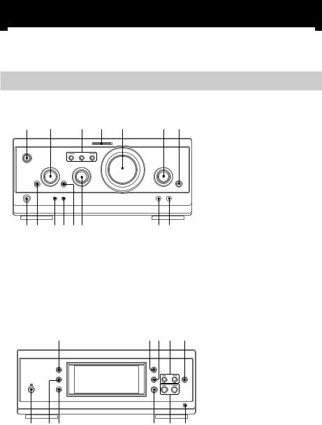
Main unit
A/V amplifier
1 |
2 |
3 |
4 |
5 |
6 7 |
|
A |
B |
C |
|
|
|
O |
|
|
|
|
|
P p |
|
|
|
|
|
o |
|
|
|
|
qg qf qdqsqaq; |
98 |
CINEMA STUDIO A–C3 (24) DIGITAL 7 (31, 35) ENTER/O/o/P/p 2 (10, 12,
13, 15, 21, 22, 26–30) EQ qa (27)
EQ ON/OFF qs (10, 27) FILE SELECT q; (23, 28)
FUNCTION 6 (10, 14, 15, 20, 21, 31)
MIC jack (Except for European model) 9 (31)
MIC LEVEL (Except for European model) 8 (31)
MULTI CHANNEL DECODING indicator 4 (25)
PHONES jack qg
SET UP qd (10, 12, 26, 28, 29) SUR qf (25)
VOLUME 5
@/1 (power) 1 (9, 10, 17, 35)
Tuner
qh |
qjqk ql |
w; |
|
|
– |
+ |
|
|
– |
+ |
|
wh wgwf |
wd ws |
wa |
|
CLOCK/TIMER wg (13, 21, 29) DISPLAY qh (13, 16, 18, 29, 35) ENTER w; (17, 18)
IR receptor wh
PRESET +/–ws (17, 18)
PTY (European model only) wa (18)
STEREO/MONO qj (17) TIMER SELECT wf (22, 30) TUNER/BAND wd (17) TUNER MEMORY qk (17) TUNING +/–ql (17)
4
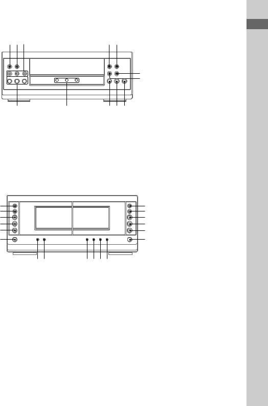
CD player
wjwkwl |
|
e; ea |
|
DISC 1–3ek (14, 15, 21) |
|
|
|
|
|
|
DISC 1–3 indicatorsej |
|
|
|
|
|
DISC 1–3Z (eject) wl (14) |
|
|
|
|
|
PLAY MODE wj (14, 15, 21) |
|
|
m |
M |
|
REPEAT wk (14) |
|
|
. |
> |
es |
N (play) eh (14, 15) |
1 |
2 3 |
H |
S x |
ed |
X (pause) eg (14) |
|
|
|
|
|
x (stop) ef (14, 20) |
|
|
|
|
|
. (go back) ed (14, 15, 21) |
|
|
|
|
|
> (go forward) es (14, 15, 21) |
ek |
ej |
ehegef |
|
m (rewind) e; (14) |
|
|
M (fast forward) ea (14) |
||||
|
|
|
|
|
|
Cassette deck
|
|
|
|
|
|
CD SYNC rh (20, 21) |
th |
> M |
|
|
M > |
el |
DIRECTION t; (19, 20, 21) |
tg |
. m |
|
|
m . |
r; |
DOLBY NR rl (19, 20) |
tf |
H |
hAUTO REVERSE H |
hAUTO REVERSE H |
H |
ra |
EDIT rk (21) |
td |
h |
|
|
h |
rs |
HI-DUB rj (20) |
ts |
x |
|
|
x |
rd |
REC PAUSE/START rg (20, 21) |
ta |
A |
|
|
A |
rf |
– Deck A – |
|
|
|
|
|
|
N (forward play) tf (19, 35) |
|
|
|
|
|
|
n (reverse play) td (19, 35) |
|
|
t;rl |
rkrjrhrg |
|
|
x (stop) ts (19) |
|
|
|
|
|
|
M/> (fast forward/go |
|
|
|
|
|
|
forward) th (19) |
|
|
|
|
|
|
m/. (rewind/go back) tg |
|
|
|
|
|
|
(19) |
|
|
|
|
|
|
Z (eject) ta (19) |
|
|
|
|
|
|
– Deck B – |
|
|
|
|
|
|
N (forward play) ra (19, 20, 35) |
|
|
|
|
|
|
n (reverse play) rs (19, 20, 35) |
|
|
|
|
|
|
x (stop) rd (19, 20) |
|
|
|
|
|
|
M/> (fast forward/go |
|
|
|
|
|
|
forward) el (19) |
|
|
|
|
|
|
m/. (rewind/go back) r; |
|
|
|
|
|
|
(19) |
|
|
|
|
|
|
Z (eject) rf (19) |
Identification Parts
5
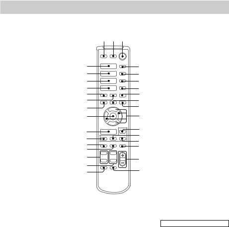
Remote Control
1 2 3
es ea e; wl wk wj wh
wg
H
hH
hH
.> x
m M X
O
P p
o
4
5
6
7
8
9
q;
qa
wf |
qs |
|
qd |
||
wd |
||
qf |
||
ws |
||
qg |
||
wa |
||
|
w; |
qh |
ql |
|
qk |
qj |
CD H es (14, 15) CHECK 5 (15) CLEAR 6 (15)
CLOCK/TIMER SELECT qj (30)
CLOCK/TIMER SET qk (13, 21, 29)
DBFB qg (23)
DISPLAY ws (13, 16, 18, 29, 35) D.SKIP 4 (14)
ENTER wg (10, 12, 13, 15, 17, 18, 21, 22, 26–30)
EQ qd (27)
EQ ON/OFF qf (10, 28) FUNCTION wf (10, 14, 15, 20,
21, 31) GROOVE wa (23)
SET UP qs (10, 12, 26, 28, 29) SLEEP 7 (29)
SUR wd (25)
TAPE A hH ea (19, 35) TAPE B hH e; (19, 20, 35) TUNER/BAND wl (17) TUNING + 9 (17)
TUNING –wh (17) TV CH +/–ql
TV VOL +/–w;
TV @/1 2
TV/VIDEO 1 VOL +/–qh
BUTTON DESCRIPTIONS
@/1 (power) 3 X (pause) q; x (stop) 8
. (go back) wk > (go forward) wj m (rewind) wh M (fast forward) 9
O/o/P/p qa
6

Getting Started
Hooking up the system
Do the following procedure 1 to 8 to hook up your system using the supplied cords and accessories.
Before connecting, place the system as described below.
|
FM antenna |
|
AM loop antenna |
Rear speaker |
Center speaker |
(Right) |
4 |
5 |
Rear speaker (Left)
4 |
|
Tuner |
6 |
1 2D |
2A
2B
A/V amplifier
3 7
 8
8
4 5
CD player
 2C
2C
Cassette deck
|
2E |
3 |
3 |
Front speaker |
Front speaker |
(Right) |
(Left) |
continued
Started Getting
7
Hooking up the system (continued)
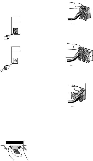
1Connect the CD player and the tuner with the optical cable.
Connect from the OPTICAL OUT jack on the CD player to the OPTICAL IN jack on the tuner.
1 Remove the cover of the jack.
OPTICAL
IN
FROM
CDP-S3
2 Connect the optical cable.
OPTICAL
IN
FROM
CDP-S3
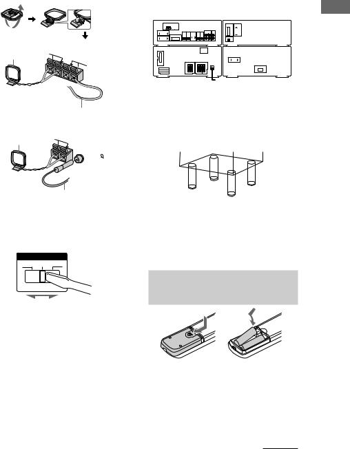
2Connect the flat system control cables to the SYSTEM CONTROL connectors until it clicks.
Connect to the same colored jack in the order indicated on the rear panel.
A SYSTEM CONTROL 1 (Red)
Connect from the tuner to the A/V amplifier.
B SYSTEM CONTROL 2 (Blue)
Connect from the tuner to the A/V amplifier.
C SYSTEM CONTROL 3 (Black)
Connect from the CD player to the tuner.
D SYSTEM CONTROL 4 (Black)
Connect from the tuner to the cassette deck.
E SYSTEM CONTROL 5 (White)
Connect from the cassette deck to the CD player.
To disconnect
SYSTEM CONTROL 3
FROM CDP-S3
3 Connect the front speakers.
Connect the speaker cords to the FRONT SPEAKER jacks.
Insert only the stripped portion.
R |
L |
|
|
+ |
|
– |
|
Red/Solid (3)
Black/Stripe (#)
4Connect the rear speakers.
Connect the speaker cords to the REAR
SPEAKER jacks.
Insert only the stripped portion.
+ |
R |
L |
|
||
|
|
|
+ |
|
|
– |
|
|
Gray/Solid (3) |
|
|
Black/Stripe (#) |
||
5Connect the center speaker.
Connect the speaker cords to the CENTER
SPEAKER jacks.
Insert only the stripped portion.
+ |
R |
L |
|
||
|
|
|
+ |
|
|
– |
|
|
Gray/Solid (3)
Black/Stripe (#)
8
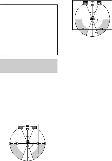
6Connect the FM/AM antennas.
Set up the AM loop antenna, then connect it.
Jack type A
AM loop antenna |
AM |
FM75
Extend the FM lead
antenna horizontally.
Jack type B
AM loop antenna |
AM |
|
 FM75
FM75
COAXIAL
Extend the FM lead antenna horizontally.
7For models with a voltage selector, set VOLTAGE SELECTOR to the position of your local power line voltage.
VOLTAGE SELECTOR
230-240V 220V 120V
8Connect the power cord to a wall outlet.
The demonstration appears in the display. When you press ?/1, the system turns on and the demonstration automatically ends.
If the supplied adaptor on the plug does not fit your wall outlet, detach it from the plug
(only for models equipped with an adaptor).
Tip
You can place the components as described below. In this case, place the components first, then connect the components.
Tuner |
|
|
|
|
|
|
|
|
CD player |
||||||||||||||||||||||||||||||
|
|
|
|
|
|
|
|
|
|
|
|
|
|
|
|
|
|
|
|
|
|
|
|
|
|
|
|
|
|
|
|
|
|
|
|
|
|
|
|
|
|
|
|
|
|
|
|
|
|
|
|
|
|
|
|
|
|
|
|
|
|
|
|
|
|
|
|
|
|
|
|
|
|
|
|
|
|
|
|
|
|
|
|
|
|
|
|
|
|
|
|
|
|
|
|
|
|
|
|
|
|
|
|
|
|
|
|
|
|
|
|
|
|
|
|
|
|
|
|
|
|
|
|
|
|
|
|
|
|
|
|
|
|
|
|
|
|
|
|
|
|
|
|
|
|
|
|
|
|
|
|
|
|
|
|
|
|
|
|
|
|
|
|
|
|
|
|
|
|
|
|
|
|
|
|
|
|
|
|
|
|
|
|
|
|
|
|
|
|
|
|
|
|
|
|
|
|
|
|
|
|
|
|
|
|
|
|
|
|
|
|
|
|
|
|
|
|
|
|
|
|
|
|
|
|
|
|
|
|
|
|
|
|
|
|
|
|
|
|
|
|
|
|
|
|
|
|
|
|
|
|
|
|
|
|
|
|
|
|
|
|
|
|
|
|
|
|
|
|
|
|
|
|
|
|
|
|
|
|
|
|
|
|
|
|
|
|
|
|
|
|
|
|
|
|
|
|
|
|
|
|
|
|
|
|
|
|
|
|
|
|
|
|
|
|
|
|
|
|
|
|
|
|
|
|
|
|
|
|
|
|
|
|
|
|
|
|
|
|
|
|
|
|
|
|
|
|
|
|
|
|
|
|
|
|
|
|
|
|
|
|
|
|
|
|
|
|
|
|
|
|
|
|
|
|
|
|
|
|
|
|
|
|
|
|
|
|
|
|
|
|
|
|
|
|
|
|
|
|
A/V amplifier |
Cassette deck |
To attack the center and rear speaker pads
Attach the supplied center and rear speaker pads to the bottom of the speakers to stabilize the speakers and prevent them from slipping.
Notes
•Keep the speaker cords away from the antennas to prevent noise.
•Do not place the rear speakers on top of a TV. This may cause color distortion in the TV screen.
•Be sure to connect both left and right rear speakers. Otherwise, the sound will not be heard.
Inserting two size AA (R6)
batteries into the remote
|
] |
|
} |
} |
|
] |
||
|
Tip
When the remote no longer operates the system, replace both batteries with new ones.
Note
If you do not use the remote for a long period of time, remove the batteries to avoid possible damage from battery leakage.
continued
Started Getting
9
Inserting two size AA (R6) batteries into the remote (continued)
Notice for carrying this system
Do the following to protect the CD mechanism.
1Turn on the system, then turn FUNCTION to select “CD”.
Make sure that all discs are removed from the unit.
2While holding down EQ ON/OFF, press ?/1 until “LOCK” appears.
3Release ?/1 first, then release EQ ON/ OFF.
4Unplug the AC power cord.
Multi channel surround
setup
For the best possible surround sound, all speakers should be the same distance from the listening position (A). However, this unit lets you to place the center speaker up to 1.5 meters closer (B) and the rear speakers up to
4.5 meters closer (C) to the listening position. The front speakers can be placed from 1.0 to 12.0 meters from the listening position (A).
You can place the rear speakers either behind you or to the side, depending on the shape of your room (etc.).
When placing rear speakers to your side
B |
A A
45°
C |
C |
90°
20°
When placing rear speakers behind you
B |
A A
45°
C |
C |
90°
20°
Note
Do not place the center speaker farther away from the listening position than the front speakers.
Specifying the speaker parameters
1 Press SET UP.
2 Press P or p repeatedly to select “SP. SETUP”.
3 Press ENTER (A/V amplifier or remote).
4 Press P or p repeatedly to select the parameter you want to adjust.
See the table on page 38 for the speaker parameters.
5 Press O or o repeatedly to select the setting you want.
The setting is stored.
6 Repeat steps 4 and 5 to set the speaker parameters.
7 Press ENTER (A/V amplifier or remote).
x Center speaker selection (CENTER)
•If you connect a center speaker, select “YES”.
•If you do not connect a center speaker, select “NO”. The sound of the center channel will be output from the front speakers.
x Rear speaker selection (REAR)
•If you connect rear speakers, select “YES”.
•If you do not connect rear speakers, select “NO”.
10
x Rear speaker position (R.PL.)*
This parameter lets you specify the location of your rear speakers for proper implementation of the Digital Cinema Sound surround modes in the “VIRTUAL” sound fields. Refer to the illustration below.
•Select “SIDE” if the location of your rear speakers corresponds to section A.
•Select “MIDDLE” if the location of your rear speakers corresponds to section B.
•Select “BEHIND” if the location of your rear speakers corresponds to section C.
This setting only effects the surround modes in the “VIRTUAL” sound fields (“VIRTUAL” indicator in the display lights up).
The bass frequencies are effectively reproduced from the speakers.
|
90° |
|
A |
60° |
A |
|
|
|
B |
30° B |
|
CC
20°
x Rear speaker height (R.HGT.)*
This parameter lets you specify the height of your rear speakers for proper implementation of the Digital Cinema Sound surround modes in the “VIRTUAL” sound fields. Refer to the illustration below.
•Select “LOW” if the location of your rear speakers corresponds to section A.
•Select “HIGH” if the location of your rear speakers corresponds to section B.
This setting only effects the surround modes in the “VIRTUAL” sound fields (“VIRTUAL” indicator in the display lights up).
B 
 B
B
 60
60
AA
30
*These parameters are not available when “Rear speaker selection (REAR)” is set to “NO”.
Tip
The rear speaker position parameter is designed specifically for implementation of the Digital Cinema Sound modes in the “VIRTUAL” sound fields.
With the Digital Cinema Sound modes, speaker position is not as critical as other modes. All of the modes in the “VIRTUAL” sound fields were designed under the premise that the rear speaker would be located behind the listening position, but presentation remains fairly consistent even with the rear speakers positioned at a rather wide angle. However, if the speakers are pointing toward the listener from the immediate left and right of the listening position, the “VIRTUAL” sound fields will not be effective unless the rear speaker position parameter is set to “SIDE”.
Nevertheless, each listening environment has many variables, like wall reflections, and you may obtain better results using “BEHIND” or “MIDDLE” if your speakers are located high above the listening position, even if they are to the immediate left and right. Therefore, although it may result in a setting contrary to the “Rear speaker position” explanation, we recommend that you playback multi channel surround encoded software and listen to the effect each setting has on your listening environment. Choose the setting that provides a good sense of spaciousness and that best succeeds in forming a cohesive space between the surround sound from the rear speakers and the sound of the front speakers. If you are not sure which sounds best, select “BEHIND” and then use the speaker distance parameter and speaker level adjustments to obtain proper balance.
continued
Started Getting
11
Multi channel surround setup (continued)
x Subwoofer selection (SUB W.)
•If you connect a subwoofer, select “YES”.
•If you do not connect a subwoofer, select “NO”.
•In order to take full advantage of the Dolby Digital bass redirection circuitry, we recommend setting the subwoofer’s cut off frequency as high as possible.
x Front speaker distance (F.DIST.)
Set the distance from your listening position to the front (left or right) speaker (A on page 10).
x Center speaker distance (C.DIST.)
Set the distance from your listening position to the center speaker (B on page 10).
x Rear speaker distance (R.DIST.)
Set the distance from your listening position to the rear (left or right) speaker (C on page 10).
Tip
This unit allows you to input the speaker position in terms of distance. However, it is not possible to set the center speaker further than the front speakers.
Also, the center speaker cannot be set more that 1.5 meters closer than the front speakers. Likewise, the rear speakers can not be set farther away from the listening position than the front speakers. And they can be no more than 4.5 meters closer.
This is because incorrect speaker placement is not conducive to the enjoyment of surround sound. Please note that, setting the speaker distance closer than the actual location of the speakers will cause a delay in the output of the sound from that speaker. In other words, the speaker will sound like it is farther away.
For example, setting the center speaker distance 1–2 m closer than the actual speaker position will create a fairly realistic sensation of being “inside” the screen. If you cannot obtain a satisfactory surround effect because the rear speakers are too close, setting the rear speaker distance closer (shorter) than the actual distance will create a larger soundstage. Adjusting these parameter while listening to the sound often results in much better surround sound. Give it a try!
x Distance unit (DIST.UNIT)
Lets you select either feet or meters as the unit of measure for setting distances.
To reset the speaker settings
1 Press SET UP.
2 Press P or p repeatedly to select “RESET MENU”.
3 Press ENTER (A/V amplifier or remote).
4 Press P or p repeatedly to select “SP. SET. RESET”.
5 Press ENTER (A/V amplifier or remote).
All the speaker settings are reset to the factory settings.
To cancel
Press SET UP.
Adjusting the speaker volume
1 Press SET UP.
2 Press P or p repeatedly to select “TEST TONE”.
3 Press ENTER (A/V amplifier or remote).
4 Press O or o repeatedly to select “ON”.
You will hear the test tone from each speaker in sequence.
5 Adjust the LEVEL parameters so that the volume of the test tone from each speaker sounds the same when you are in your main listening position (see page 26).
6 To turn off the test tone, repeat steps 1 to 3 and press O or o repeatedly to select “OFF”.
Notes
•The adjustments are shown in the display during adjustment.
•Although these adjustments can be made via the front panel, we recommend you follow the procedure described above and adjust the speaker levels from your listening position using SET UP button on the remote.
12

Setting the time
1 Turn on the system.
2 Press CLOCK/TIMER (or CLOCK/TIMER SET on the remote).
When you set the time for the first time, proceed to step 5.
3 Press O or o repeatedly to select “CLOCK SET”.
4 Press ENTER (A/V amplifier or remote).
5 Press O or o repeatedly to set the hour.
6 Press ENTER (A/V amplifier or remote).
7 Press O or o repeatedly to set the minutes.
8 Press ENTER (A/V amplifier or remote).
Tip
If you have made a mistake or want to change the time, start over from step 2.
Note
The clock settings are canceled when you disconnect the power cord or if a power failure occurs.
Saving the power in
standby mode
Press DISPLAY repeatedly when the power is off.
Each time you press the button, the system switches cyclically as follows:
Demonstration t Clock t Power Saving
Mode
To cancel the Power Saving Mode
Press DISPLAY once to show the demonstration, twice to show the clock display.
Tips
•?/1indicator lights up even in the Power Saving Mode.
•The timer functions during the Power Saving Mode.
Note
During the Power Saving Mode, the following functions do not work:
–Setting the time.
–Changing the AM tuning interval (except for European and Middle Eastern models).
–One Touch Play function.
Started Getting
13
CD
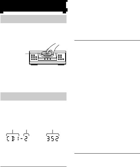
Loading a CD
1 Press one of the DISC 1–3Z buttons.
The disc tray slides out.
2 Place a CD with the label side up on the disc tray.
When you play a |
|
|
|
|
|
|
CD single, place it |
|
|
|
|
|
|
on the inner circle |
1 |
2 |
3 |
H |
S |
x |
of the tray. |
|
|
|
|
|
|
To insert additional discs, press Z of the other numbers to open the disc tray.
3 Press the same button to close the disc tray.
Playing a CD
— Normal Play/Repeat Play/Shuffle
Play
This unit lets you play the CD in different play modes.
Disc tray number Track number |
Playing time |
|
|
|
|
|
|
|
1 Turn FUNCTION to select “CD”.
2 When playback is stopped, press PLAY MODE repeatedly until the mode you want appears in the display.
Select |
To play |
ALL DISCS |
All CDs in the disc tray |
|
continuously. |
|
|
1 DISC |
The CD you have selected in the |
|
original order. |
|
|
ALL DISCS |
The tracks on all CDs in random |
SHUFFLE |
order. |
|
|
1 DISC |
The tracks on the CD you have |
SHUFFLE |
selected in random |
|
order. |
|
|
PROGRAM |
The tracks on all CDs in the |
|
order you want them to be played |
|
(see “Programming the CD |
|
tracks” on page 15). |
|
|
3 Press N (CD) (or CD H on the remote).
Tip
You cannot change the play mode during playback.
Other operations
To |
Do this |
Stop playback |
Press x (CD). |
|
|
Pause playback |
Press X. |
|
Press again to resume playback. |
|
|
Select a track |
During playback or pause, press |
|
> (CD) (to go forward) or |
|
. (CD) (to go back). |
|
|
Find a point in a |
Press and hold M or m |
track |
(CD) during playback and |
|
release it at the desired point. |
|
|
Select a CD when |
Press one of the DISC 1–3 |
playback is |
buttons (or D.SKIP on the |
stopped |
remote). |
|
|
Switch to CD |
Press one of the DISC 1–3 |
function from |
buttons (Automatic Source |
another source |
Selection). |
|
|
Play repeatedly |
Press REPEAT during playback |
(Repeat Play) |
until “REPEAT” or “REPEAT |
|
1” appears. |
|
REPEAT*: For all the tracks on |
|
the CD up to 5 times. |
|
REPEAT 1: For a single track |
|
only. |
|
To cancel Repeat Play, press |
|
REPEAT until “REPEAT” and |
|
“REPEAT 1” disappears. |
|
|
Remove the CD |
Press one of the DISC 1–3Z |
|
buttons. |
*You cannot use this function during ALL DISCS SHUFFLE.
Note
Do not use force to close the disc tray, as this may cause the CD player trouble. Always close the disc tray by pressing one of the DISC 1–3Z buttons.
14
Loading...