


DCR-TRV12E
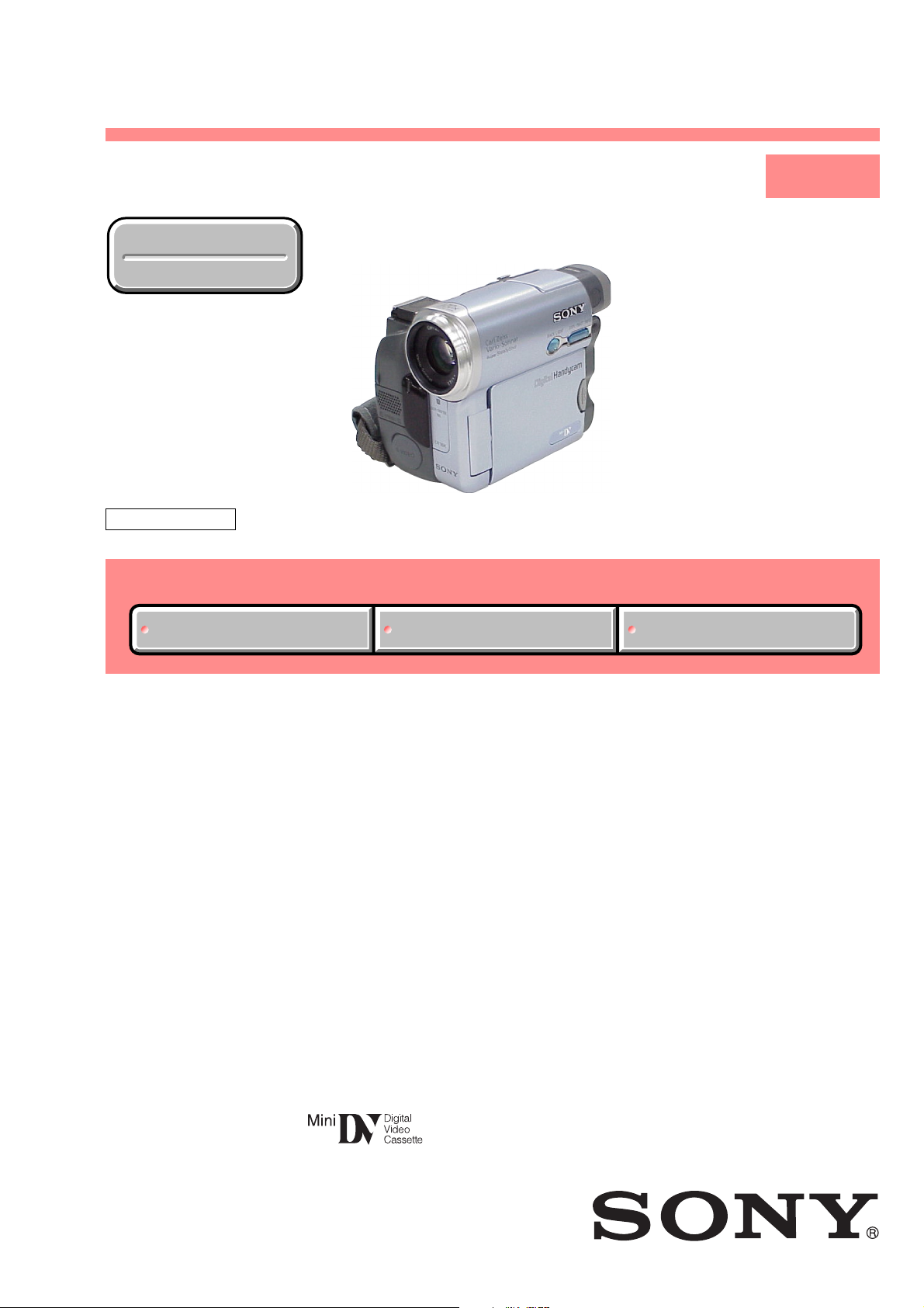
SERVICE MANUAL
• INSTRUCTION MANUAL is shown at the end of this document.
Revision History
Revision History
Ver 1.1 2003. 11
LEVEL 1
Link
SELF DIAGNOSIS FUNCTION
ORNAMENTAL PARTSSPECIFICATIONS
SELF DIAGNOSIS FUNCTION
ORNAMENTAL PARTSSPECIFICATIONS
Link
US Model
Canadian Model
Korea Model
DCR-TRV19
AEP Model
East European Model
North European Model
DCR-TRV12E/TRV14E/TRV19E
UK Model
DCR-TRV14E/TRV19E
E Model
Hong Kong Model
DCR-TRV19/TRV19E
Australian Model
Chinese Model
DCR-TRV19E
Z MECHANISM
DCR-TRV12E/TRV14E/
TRV19/TRV19E
RMT-814
DIGITAL VIDEO CAMERA RECORDER

— 2 —
DCR-TRV12E/TRV14E/TRV19/TRV19E
SPECIFICATIONS
Video camera
recorder
System
Video recording system
2 rotary heads
Helical scanning system
Audio recording system
Rotary heads, PCM system
Quantization: 12 bits (Fs 32 kHz,
stereo 1, stereo 2), 16 bits
DCR-TRV19:
NTSC colour, EIA standards
DCR-TRV12E/TRV14E/TRV19E:
(Fs 48 kHz, stereo)
Video signal
PAL colour, CCIR standards
Usable cassette
Mini DV cassette with the
mark printed
Tape speed
SP: Approx. 18.81 mm/s
LP: Approx. 12.56 mm/s
Recording/playback time
(using cassette DVM60)
SP: 1 hour
LP: 1.5 hours
Fastforward/rewind time
(using cassette DVM60)
Approx. 2 min. and 40 seconds
Viewfinder
Electric viewfinder
black and white
Image device
DCR-TRV12E/TRV14E/TRV19E:
4.5 mm (1/4 type)
CCD (Charge Coupled Device)
Gross:
DCR-TRV19:
DCR-TRV12E/TRV14E/TRV19E:
Effective (moving):
DCR-TRV19: Approx. 340 000 pixels
DCR-TRV12E/TRV14E/TRV19E:
Approx. 680 000 pixels
DCR-TRV19:
DCR-TRV12E/TRV14E/TRV19E:
0.3 Vp-p
0.286 Vp-p
Lens
Carl Zeiss Vario-Sonnar
Combined power zoom lens
Filter diameter: 30 mm
(1 3/16 in)
10× (Optical), 120× (Digital)
Focal length
3.3 – 33 mm (5/32 – 1 5/16 in.)
1)
42 – 420 mm (1 11/16 – 16 5/8
in.)
2)
1)
When converted to a 35 mm still
camera
2)
In CAMERA mode
Colour temperature
Auto, HOLD, INDOOR (3 200 K),
OUTDOOR (5 800 K)
Minimum illumination
5 lx (lux) (F1.7)
0 lx (lux) (in the NightShot
mode)*
* Objects unable to be seen due to
the dark can be shot with
infrared lighting.
Input/Output connectors
S video output
4-pin mini DIN
(DCR-TRV19/TRV19E only)
Luminance signal: 1 Vp-p,
75 Ω
75 Ω
(ohms), unbalanced
Chrominance signal:
(ohms), unbalanced
Audio/Video output
AV MINI JACK, 1 Vp-p,
75 Ω (ohms), unbalanced
327 mV, (at output impedance
more than 47 kΩ (kilohms))
Output impedance with less than
2.2 kΩ (kilohms)/Stereo minijack
(ø 3.5 mm)
Input impedance more than
47 kΩ (kilohms)
DV input (DCR-TRV19/TRV19E
only)/output
4-pin connector
Headphone jack
Stereo minijack (ø 3.5 mm)
LANC jack
Stereo mini-minijack (ø 2.5 mm)
USB jack
mini-B
MIC jack
Minijack, 0.388 mV low impedance
with 2.5 to 3.0 V DC, output
impedance 6.8 kΩ (kilohms)
(ø 3.5 mm)
Stereo type
LCD screen
Picture
6.2 cm (2.5 type)
50.3 × 37.4 mm (2 × 1 1/2 in.)
Total dot number
123 200 (560 × 220)
General
Power requirements
7.2 V (battery pack)
8.4 V (AC Adaptor)
Average power consumption
(when using the battery pack)
3.3 W
1)
2.5 W
2)
1)
During camera recording using
LCD
2)
Viewfinder
Operating temperature
0°C to 40°C (32°F to 104°F)
Storage temperature
–20°C to + 60°C
(–4°F to + 140°F)
Dimensions (approx.)
71 × 90 × 112 mm
(2 7/8 × 3 5/8 × 4 1/2 in.) (w/h/d)
Mass (approx.)
Main unit only
520 g (1 lb 2 oz)
Including the rechargeable battery
pack NP-FM30, cassette DVM60
and lens cap
610 g (1 lb 5 oz)
Supplied accessories
See page 3.
AC Adaptor
AC-L15A/L15B
Power requirements
100 – 240 V AC, 50/60 Hz
Current consumption
0.35 – 0.18 A
Power consumption
18 W
Output voltage
DC OUT: 8.4 V, 1.5 A
Operating temperature
0°C to 40°C (32°F to 104°F)
Storage temperature
–20°C to + 60°C
(–4°F to + 140°F)
Dimensions (approx.)
56 × 31 × 100 mm
(2 1/4 × 1 1/4 × 4 in.) (w/h/d)
excluding projecting parts
Mass (approx.)
190 g (6.7 oz)
excluding power cord
Rechargeable
battery pack
NP-FM30
Maximum output voltage
DC 8.4 V
Output voltage
DC 7.2 V
Capacity
5.0 Wh (700 mAh)
Dimensions (approx.)
38.2 × 20.5 × 55.6 mm
(1 9/16 × 13/16 × 2 1/4 in.)
(w/h/d)
Mass (approx.)
65 g (2.3 oz)
Operating temperature
0°C to 40°C (32°F to 104°F)
Type
Lithium ion
Design and specifications are
subject to change without notice.
COVER
COVER
— 3 —
DCR-TRV12E/TRV14E/TRV19/TRV19E
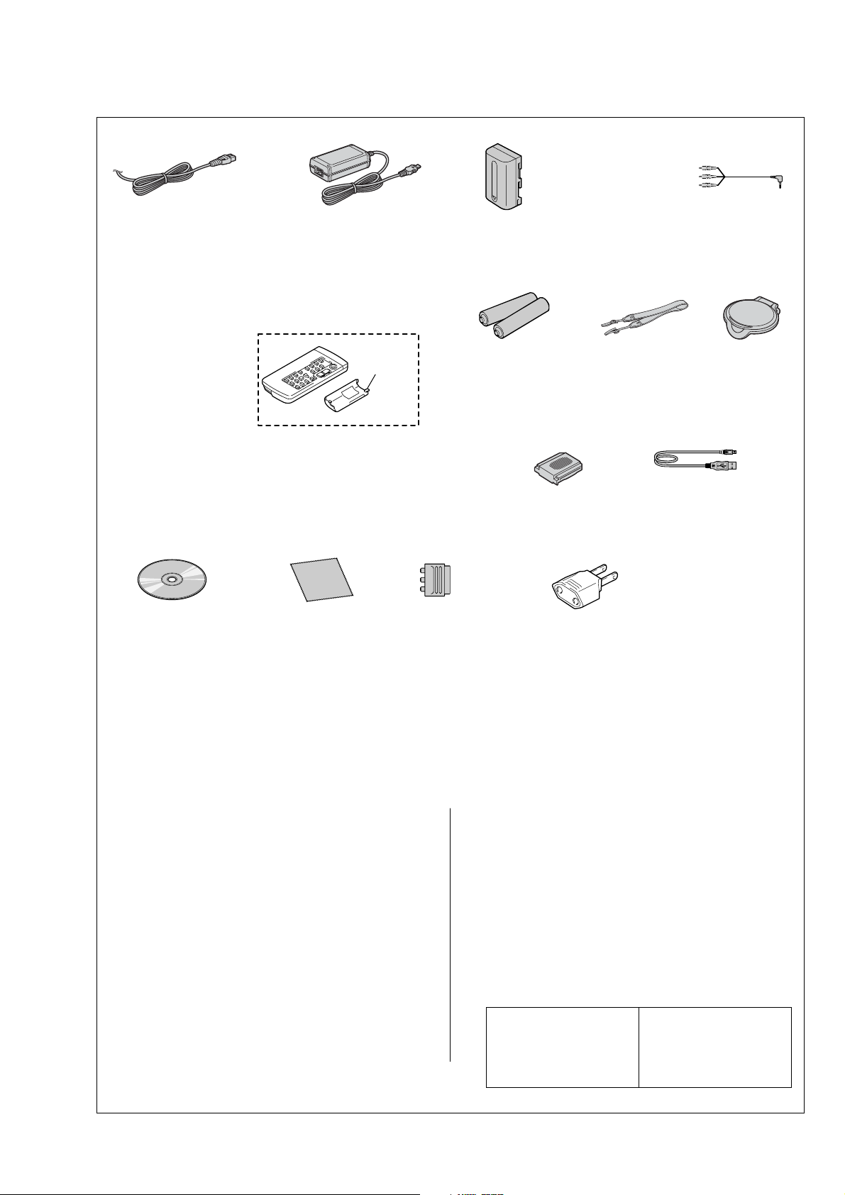
Checking supplied accessories.
Make sure that the following accessories are supplied with your camcorder.
Power cord (Main lead)(1)
(AUS model)
0
1-696-819-21
Power cord (Main lead)(1)
(AEP, E, EE, NE model)
0
1-769-608-11
Power cord (Main lead)(1)
(CH model)
0
1-782-476-11
Power cord (Main lead)(1)
(UK, HK model)
0
1-783-374-11
Power cord (Main lead)(1)
(US, CND model)
0
1-790-107-22
Power cord (Main lead)(1)
(KR model)
0
1-776-985-11
AC power adaptor (1) (AC-L15A)
(US, CND, AEP, UK, E, HK, AUS, EE,
NE, KR model)
0
1-477-533-31
AC power adaptor (1) (AC-L15A)
(CH model)
0
1-477-533-41
R6 (size AA) batteries
for the Remote
Commander (2)
(not supplied)
21-pin adaptor (1)
(AEP, UK, EE, NE
model)
1-770-783-21
Shoulder strap (1)
3-987-015-01
A/V connecting cable
(1.5m) (1)
1-824-097-11
NP-FM30 battery pack (1)
0
A-7096-387-A (US, CND)
0
A-7096-388-B (EXCEPT US,CND)
Wireless Remote Commander (1)
(RMT-814E)
1-475-141-61
(EXCEPT DCR-TRV12E)
CD-ROM
(SPVD-010 USB Driver) (1)
(EXCEPT US, CND model)
3-078-942-03
CD-ROM
(SPVD-010(I) USB Driver) (1)
(US,CND model)
3-078-943-03
2-pin conversion adaptor (1)
(E,HK only)
1-569-008-12
Note :
The components identified by
mark 0 or dotted line with mark
0 are critical for safety.
Replace only with part number
specified.
Note :
Les composants identifiés par
une marque 0 sont critiques
pour la sécurité.
Ne les remplacer que par une
pièce portant le numéro spécifié.
Lens cap (1)
X-3953-088-1
Lid Battery
Case
(3-742-854-01)
Shoe cover (1)
3-080-571-01
Cleaning cloth (1)
3-073-861-01
USB cable (1)
1-823-931-11
• Abbreviation
CND : Canadian model
EE : East European model
NE : North European model
HK : Hong Kong model
AUS : Australian model
CH : Chinese model
KR : Korea model
Other accessories
3-080-368-11 MANUAL, INSTRUCTION(ENGLISH/FRENCH)
(TRV12E:AEP/TRV14E:AEP,UK/TRV19E:AEP,
UK,E,HK,AUS,CH)
3-080-368-21 MANUAL, INSTRUCTION(SPANISH/PORTUGUESE)
(TRV12E:AEP/TRV14E:AEP/TRV19E:AEP)
3-080-368-31 MANUAL, INSTRUCTION(ITALIAEN/GREEK)
(TRV12E:AEP/TRV14E:AEP/TRV19E:AEP)
3-080-368-41 MANUAL, INSTRUCTION(GERMAN/DUTCH)
(TRV12E:AEP/TRV14E:AEP/TRV19E:AEP)
3-080-368-51 MANUAL, INSTRUCTION(SWEDISH/RUSSIAN)
(TRV12E:NE/TRV14E:NE/TRV19E:NE,E)
3-080-368-61 MANUAL, INSTRUCTION(DANISH/FINNISH)
(TRV12E:NE/TRV14E:NE/TRV19E:NE)
3-080-368-71 MANUAL, INSTRUCTION(ARABIC/PERSIAN)(TRV19E:E)
3-080-368-81 MANUAL, INSTRUCTION(TRADITIONAL CHINESE)
(TRV19E:HK)
3-080-368-91 MANUAL, INSTRUCTION(SIMPLIFIED CHINESE)
(TRV19E:E,CH)
3-080-369-11 MANUAL, INSTRUCTION(ENGLISH)
(TRV19:US,CND,E,HK)
3-080-369-21 MANUAL, INSTRUCTION(FRENCH)(TRV19:CND)
3-080-369-31 MANUAL, INSTRUCTION(SPANISH/PORTUGUESE)
(TRV19:E)
3-080-369-41 MANUAL, INSTRUCTION(TRADITIONAL CHINESE)
(TRV19:E,HK)
3-080-369-51 MANUAL, INSTRUCTION(KOREAN)(TRV19:KR)
3-080-369-61 MANUAL, INSTRUCTION(ARABIC)(TRV19:E)

— 4 —
DCR-TRV12E/TRV14E/TRV19/TRV19E
SAFETY-RELATED COMPONENT WARNING!!
COMPONENTS IDENTIFIED BY MARK 0 OR DOTTED LINE WITH
MARK 0 ON THE SCHEMATIC DIAGRAMS AND IN THE PARTS
LIST ARE CRITICAL TO SAFE OPERATION. REPLACE THESE
COMPONENTS WITH SONY PARTS WHOSE PART NUMBERS
APPEAR AS SHOWN IN THIS MANUAL OR IN SUPPLEMENTS
PUBLISHED BY SONY.
ATTENTION AU COMPOSANT AYANT RAPPORT
À LA SÉCURITÉ!
LES COMPOSANTS IDENTIFÉS PAR UNE MARQUE 0 SUR LES
DIAGRAMMES SCHÉMATIQUES ET LA LISTE DES PIÈCES SONT
CRITIQUES POUR LA SÉCURITÉ DE FONCTIONNEMENT. NE
REMPLACER CES COMPOSANTS QUE PAR DES PIÈSES SONY
DONT LES NUMÉROS SONT DONNÉS DANS CE MANUEL OU
DANS LES SUPPÉMENTS PUBLIÉS PAR SONY.
1. Check the area of your repair for unsoldered or poorly-soldered
connections. Check the entire board surface for solder splashes
and bridges.
2. Check the interboard wiring to ensure that no wires are
"pinched" or contact high-wattage resistors.
3. Look for unauthorized replacement parts, particularly
transistors, that were installed during a previous repair . Point
them out to the customer and recommend their replacement.
4. Look for parts which, through functioning, show obvious signs
of deterioration. Point them out to the customer and
recommend their replacement.
5. Check the B+ voltage to see it is at the values specified.
6. Flexible Circuit Board Repairing
• Keep the temperature of the soldering iron around 270˚C
during repairing.
• Do not touch the soldering iron on the same conductor of the
circuit board (within 3 times).
• Be careful not to apply force on the conductor when soldering
or unsoldering.
SAFETY CHECK-OUT
After correcting the original service problem, perform the following
safety checks before releasing the set to the customer.
CAUTION :
Danger of explosion if battery is incorrectly replaced.
Replace only with the same or equivalent type.
— 5 —
DCR-TRV12E/TRV14E/TRV19/TRV19E
1. SELF-DIAGNOSIS FUNCTION
When problems occur while the unit is operating, the self-diagnosis
function starts working, and displays on the viewfinder, or LCD
screen what to do. This function consists of two display; self-
diagnosis display and service mode display.
Details of the self-diagnosis functions are provided in the Instruction
manual.
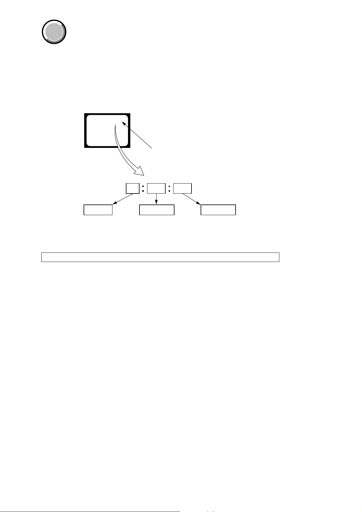
2. SELF-DIAGNOSIS DISPLAY
When problems occur while the unit is operating, the counter of the
viewfinder or LCD screen consists of an alphabet and 4-digit number ,
which blinks at 3.2Hz. This 5-character display indicates the
“repaired by:”, “block” in which the problem occurred, and “detailed
code” of the problem.
Note: The “self-diagnosis display” data will be kept even if the lithium battery (BT5201 of CK-129 board) is removed.
1 1
3 1C
Repaired by:
Refer to page 6.
Self-diagnosis Code Table.
Indicates the appropriate
step to be taken.
E.g.
31 ....Reload the tape.
32 ....Turn on power again.
Block
Detailed Code
Blinks at 3.2Hz
C : Corrected by customer
H : Corrected by dealer
E : Corrected by service
engineer
Viewfinder or LCD screen
C : 3 1 : 1 1
SELF-DIAGNOSIS FUNCTION
COVER
COVER

— 6 —
DCR-TRV12E/TRV14E/TRV19/TRV19E
3. SELF-DIAGNOSIS CODE TABLE
C
C
C
C
C
C
C
C
C
C
C
C
C
C
C
C
C
C
C
C
C
C
C
Block
Function
04
21
22
31
31
31
31
31
31
31
31
31
31
32
32
32
32
32
32
32
32
32
32
Detailed
Code
00
00
00
10
11
20
21
22
23
24
30
40
42
10
11
20
21
22
23
24
30
40
42
Symptom/State
Non-standard battery is used.
Condensation.
Video head is dirty.
LOAD direction. Loading does not
complete within specified time
UNLOAD direction. Loading does not
complete within specified time
T reel side tape slacking when unloading
.
Winding S reel fault when counting the
rest of tape.
T reel fault.
S reel fault.
T reel fault.
FG fault when starting capstan.
FG fault when starting drum.
FG fault during normal drum operations.
LOAD direction loading motor time-
out.
UNLOAD direction loading motor
time-out.
T reel side tape slacking when
unloading.
Winding S reel fault when counting the
rest of tape.
T reel fault.
S reel fault.
T reel fault.
FG fault when starting capstan.
FG fault when starting drum
FG fault during normal drum
operations
Self-diagnosis Code
Repaired by:
Correction
Use the info LITHIUM battery.
Remove the cassette, and insert it again after one hour.
Clean with the optional cleaning cassette.
Load the tape again, and perform operations from the beginning.
Load the tape again, and perform operations from the beginning.
Load the tape again, and perform operations from the beginning.
Load the tape again, and perform operations from the beginning.
Load the tape again, and perform operations from the beginning.
Load the tape again, and perform operations from the beginning.
Load the tape again, and perform operations from the beginning.
Load the tape again, and perform operations from the beginning.
Load the tape again, and perform operations from the beginning.
Load the tape again, and perform operations from the beginning.
Remove the battery or power cable, connect, and perform
operations from the beginning.
Remove the battery or power cable, connect, and perform
operations from the beginning.
Remove the battery or power cable, connect, and perform
operations from the beginning.
Remove the battery or power cable, connect, and perform
operations from the beginning.
Remove the battery or power cable, connect, and perform
operations from the beginning.
Remove the battery or power cable, connect, and perform
operations from the beginning.
Remove the battery or power cable, connect, and perform
operations from the beginning.
Remove the battery or power cable, connect, and perform
operations from the beginning.
Remove the battery or power cable, connect, and perform
operations from the beginning.
Remove the battery or power cable, connect, and perform
operations from the beginning.
Note: Add the sentence as follows.
If other codes are displayed, service is required.
Please send the set to a specialized center.
Ver 1.1 2003. 11
— 7 —
DCR-TRV12E/TRV14E/TRV19/TRV19E
MAIN PARTS
Note:
• Follow the disassembly procedure in the numerical order given.
• Items marked “*” are not stocked since they are seldom required for routine service.
Some delay should be anticipated when ordering these items.
• The parts numbers of such as a cabinet are also appeared in this section.
Refer to the parts number mentioned below the name of parts to order.
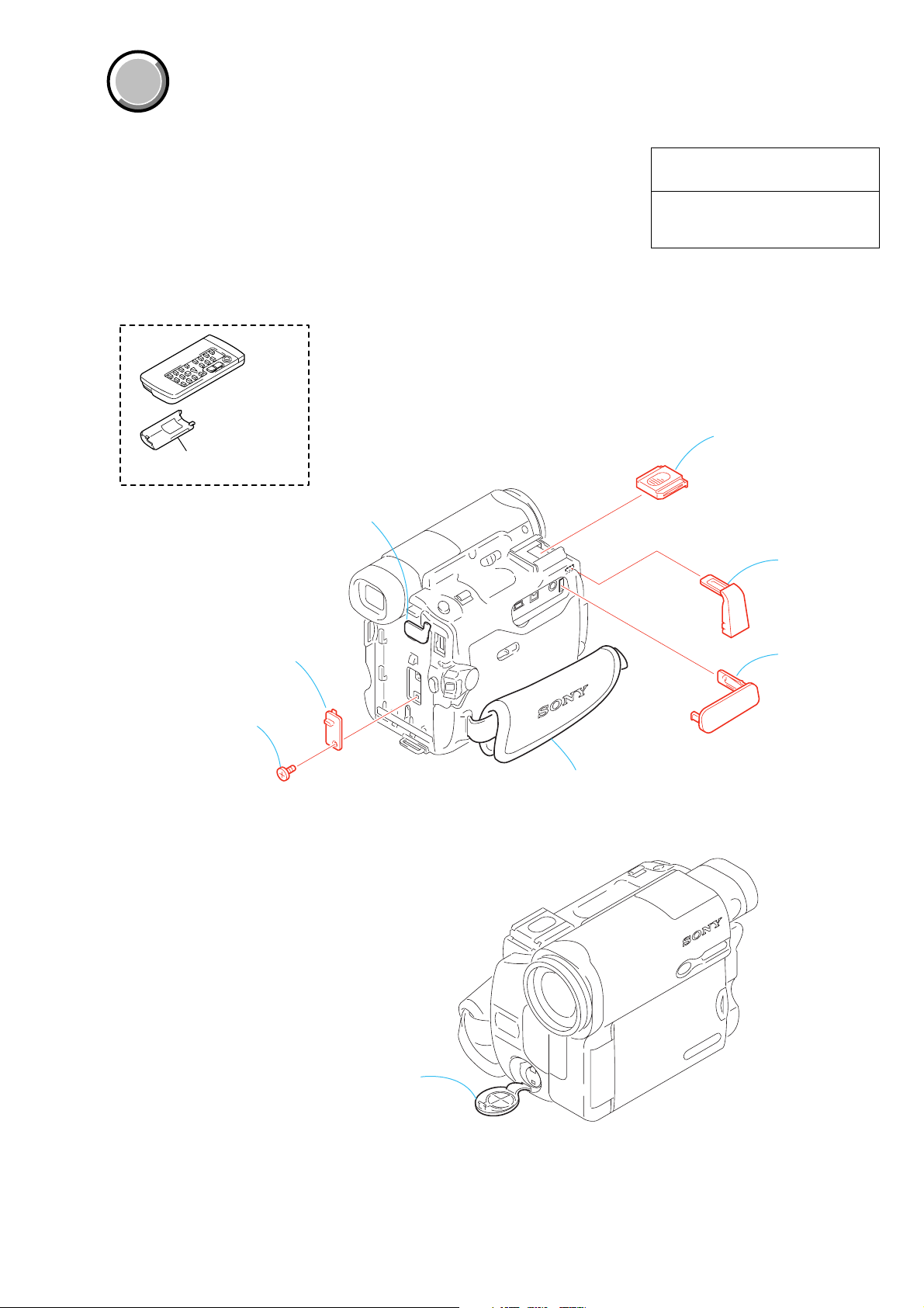
1. ORNAMENTAL PARTS
The components identified by mark 0 or
dotted line with mark 0 are critical for safety.
Replace only with part number specified.
Les composants identifiés par une marque
0 sont critiques pour la sécurité.
Ne les remplacer que par une pièce portant
le numéro spécifié.
COVER
COVER
DC-IN jack cover
Note: Disassembling the main unit
is necessary to replace it.
S terminal cover
Note: Disassembling the main unit
is necessary to replace it.
Jack cover (F)
(3-080-573-01)
Shoe cover
(3-080-571-01)
Jack cover (L)
(3-080-572-01)
Grip belt
Note: Disassembling the main unit
is necessary to replace it.
CPC lid
(3-080-570-01)
Screw
(M1.7
×
4), lock ace, p2
(3-989-735-81)
Remote commander (RMT-814E)
1-475-141-61
Battery case lid (for RMT-814E)
3-742-854-01

DCR-TRV12E/TRV14E/TRV19/TRV19E
— 8 —
Sony EMCS Co.
2003K1600-1
©2003.11
Published by DI CS Strategy Div.
9-876-224-41
3-080-369-11(1)
©2003 Sony Corporation
Operating Instructions
Before operating the unit, please read this manual thoroughly,
and retain it for future reference.
Owner’s Record
The model and serial numbers are located on the bottom. Record the
serial number in the space provided below. Refer to these numbers
whenever you call upon your Sony dealer regarding this product.
Model No. DCR-TRV ____________________ Model No. AC- ________________________
Serial No. _____________________________ Serial No. _____________________________
DCR-TRV19/TRV22/TRV33
Digital
Video Camera
Recorder
DCR-TRV33
2
Welcome!
Congratulations on your purchase of this Sony Handycam. With your Handycam, you can
capture life’s precious moments with superior picture and sound quality. Your Handycam is
loaded with advanced features, but at the same time it is very easy to use. You will soon be
producing home video that you can enjoy for years to come.
WARNING
To prevent fire or shock hazard, do
not expose the unit to rain or
moisture.
Notice
If static electricity or electromagnetism causes
data transfer to discontinue midway (fail),
restart the application or disconnect and
connect the USB cable again.
This symbol is intended to
alert the user to the presence
of uninsulated “dangerous
voltage” within the product’s
enclosure that may be of
sufficient magnitude to
constitute a risk of electric
shock to persons.
This symbol is intended to
alert the user to the presence
of important operating and
maintenance (servicing)
instructions in the literature
accompanying the appliance.
For customers in the U.S.A.
and CANADA
CAUTION
TO PREVENT ELECTRIC SHOCK, MATCH
WIDE BLADE OF PLUG TO WIDE SLOT,
FULLY INSERT.
RECYCLING LITHIUM-ION BATTERIES
Lithium-Ion batteries are
recyclable.
You can help preserve our
environment by returning
your used rechargeable
batteries to the collection and
recycling location nearest you.
For more information regarding recycling of
rechargeable batteries, call toll free 1-800-822-
8837, or visit http://www.rbrc.org/
Caution: Do not handle damaged or leaking
Lithium-Ion batteries.
“Memory Stick” (DCR-TRV22/
TRV33 only)
This device complies with Part 15 of the FCC
Rules. Operation is subject to the following
two conditions: (1) This device may not cause
harmful interference, and (2) this device must
accept any interference received, including
interference that may cause undesired
operation.
This Class B digital apparatus complies with
Canadian ICES-003.

3
For customers in the U.S.A.
If you have any questions about this product,
you may call:
Sony Customer Information Center 1-800-222-
SONY (7669)
The number below is for the FCC related
matters only.
Regulatory Information
Declaration of Conformity
Trade Name: SONY
Model No.: DCR-TRV19
Responsible Party: Sony Electronics Inc.
Address: 680 Kinderkamack
Road, Oradell,
NJ07649 U.S.A.
Telephone No.: 201-930-6972
This device complies with Part 15 of the
FCC Rules. Operation is subject to the
following two conditions: (1) This device
may not cause harmful interference, and
(2)this device must accept any interference
received, including interference that may
cause undesired operation.
Declaration of Conformity
Trade Name: SONY
Model No.: DCR-TRV22
Responsible Party: Sony Electronics Inc.
Address: 680 Kinderkamack
Road, Oradell,
NJ07649 U.S.A.
Telephone No.: 201-930-6972
This device complies with Part 15 of the
FCC Rules. Operation is subject to the
following two conditions: (1) This device
may not cause harmful interference, and
(2)this device must accept any interference
received, including interference that may
cause undesired operation.
Declaration of Conformity
Trade Name: SONY
Model No.: DCR-TRV33
Responsible Party: Sony Electronics Inc.
Address: 680 Kinderkamack
Road, Oradell,
NJ07649 U.S.A.
Telephone No.: 201-930-6972
This device complies with Part 15 of the
FCC Rules. Operation is subject to the
following two conditions: (1) This device
may not cause harmful interference, and
(2)this device must accept any interference
received, including interference that may
cause undesired operation.
CAUTION
You are cautioned that any changes or
modifications not expressly approved in this
manual could void your authority to operate
this equipment.
Note:
This equipment has been tested and found to
comply with the limits for a Class B digital
device, pursuant to Part 15 of the FCC Rules.
These limits are designed to provide
reasonable protection against harmful
interference in a residential installation. This
equipment generates, uses, and can radiate
radio frequency energy and, if not installed
and used in accordance with the instructions,
may cause harmful interference to radio
communications. However, there is no
guarantee that interference will not occur in a
particular installation. If this equipment does
cause harmful interference to radio or
television reception, which can be determined
by turning the equipment off and on, the user
is encouraged to try to correct the interference
by one or more of the following measures:
— Reorient or relocate the receiving antenna.
— Increase the separation between the
equipment and receiver.
— Connect the equipment into an outlet on a
circuit different from that to which the
receiver is connected.
— Consult the dealer or an experienced
radio/TV technician for help.
The supplied interface cable must be used with
the equipment in order to comply with the
limits for a digital device pursuant to Subpart
B of Part 15 of FCC Rules.

4
Main Features
Recording moving pictures
or still images, and playing
them back
•Recording moving pictures on the
tape (p. 25)
•Playing back the tape (p. 39)
•Recording still images on the
“Memory Stick” (DCR-TRV22/
TRV33 only) (p. 46, 114)
•Recording moving pictures on the
“Memory Stick” (DCR-TRV22/
TRV33 only) (p. 125)
•Viewing still images recorded on
the “Memory Stick” (DCR-TRV22/
TRV33 only) (p. 135)
•Viewing moving pictures recorded
on the “Memory Stick” (DCR-
TRV22/TRV33 only) (p. 137)
Capturing images on the
computer
•Viewing moving pictures recorded on
the tape using the USB cable (p. 148)
•Viewing images recorded on the
“Memory Stick” using the USB cable
(DCR-TRV22/TRV33 only) (p. 149)
•Capturing images on the computer
from your camcorder using the USB
cable (p. 161)
•Converting an analog signal into
digital to capture images onto the
computer (DCR-TRV22/TRV33 only)
(p. 173)
4
Main Features

Getting Started
5
Main Features
5
Other uses
Functions for adjusting exposure during recording
•Back light (p. 33)
•NightShot/Super NightShot*/Color Slow Shutter* (p. 34)
•PROGRAM AE (p. 62)
•Manual exposure (p. 64)
•Flexible Spot Meter (p. 65)
Functions for giving images more impact
•Digital zoom (p. 32)
The default setting is OFF. (To zoom greater than 10×,
select the digital zoom power in D ZOOM in the menu settings.)
•Fader (p. 55)
•Picture effect (p. 58, 72)
•Digital effect* (p. 59, 73)
•Title (p. 101)
•MEMORY MIX* (p. 120)
Functions for giving a natural appearance to your recordings
•PROGRAM AE (p. 62)
– SPORTS
– LANDSCAPE
•Manual focus (p. 66)
•Spot Focus (p. 67)
Functions for using after recording
•End search/Edit search/Rec Review (p. 37)
•Data code (p. 40)
•Tape PB ZOOM* (p. 74)/Memory PB ZOOM* (p. 140)
•Zero set memory (p. 75)
•Title search (p. 76)
•Digital program editing (p. 84, 130*)
* DCR-TRV22/TRV33 only
Main Features
Before you start reading this manual and operating your camcorder, check the
model number by looking at the bottom of your camcorder. The DCR-TRV33 is the
model used for illustration purposes. Otherwise, the model name is indicated in
the illustrations. Any differences in operation are clearly indicated in the text, for
example, “DCR-TRV33 only.”

6
Table of contents
Main Features ........................ 4
Quick Start Guide
Recording on tape ................................... 8
Recording on “Memory Stick”
(DCR-TRV22/TRV33 only) ........... 10
Getting Started
Using this manual ................................. 12
Checking supplied accessories............ 15
Step 1 Preparing the power source..... 16
Installing the battery pack............. 16
Charging the battery pack............. 17
Checking status of battery pack –
Battery Info ............................... 20
Connecting to a wall outlet ........... 21
Step 2 Setting the date and time ......... 22
Step 3 Using the touch panel............... 23
Recording – Basics
Recording a picture............................... 25
Shooting backlit subjects
– Back light function................ 33
Shooting in the dark
– NightShot/Super NightShot/
Color Slow Shutter .................. 34
Checking recordings
– End search/Edit search/Rec
Review ............................................. 37
Playback – Basics
Playing back tape .................................. 39
To display the screen indicators –
Display function ...................... 40
Viewing a recording on TV ................. 44
Advanced Recording
Operations
Recording still images on “Memory
Stick” during tape recording
standby or tape recording
(DCR-TRV22/TRV33 only) ........... 46
Recording a still image on a tape
– Tape Photo recording
(DCR-TRV19 only) ......................... 48
Self-timer recording .............................. 50
Adjusting the white balance
manually .......................................... 52
Using the wide mode ........................... 53
Using the fader function ...................... 55
Using special effects – Picture effect .. 58
Using special effects – Digital effect
(DCR-TRV22/TRV33 only)........... 59
Using PROGRAM AE .......................... 62
Adjusting the exposure manually ...... 64
Using spot light-metering function
– Flexible Spot Meter ..................... 65
Focusing manually................................ 66
Using spot focus function
– Spot Focus .................................... 67
Interval Recording ................................ 68
Frame by frame recording
– Frame recording .......................... 69
Using the viewfinder ............................ 70
Advanced Playback
Operations
Playing back tape with picture effect. 72
Playing back tape with digital effect
(DCR-TRV22/TRV33 only)........... 73
Enlarging images recorded on tape
– Tape PB ZOOM (DCR-TRV22/
TRV33 only) .................................... 74
Quickly locating a scene
– Zero set memory ......................... 75
Searching the boundaries of recorded
tape by title – Title search ............. 76
Searching a recording by date
– Date search ................................... 77
Searching for a photo – Photo search/
Photo scan (DCR-TRV19 only) ..... 79
Editing
Dubbing tape ......................................... 81
Dubbing only desired scenes
– Digital program editing
(on tape) ........................................... 84
Recording video or TV programs ....... 93
Inserting a scene from a VCR
– Insert editing ................................ 95
Audio dubbing ...................................... 97
Superimposing a title on a cassette
with Cassette Memory................. 101
Making your own titles ...................... 103
Labeling a cassette on a cassette
with Cassette Memory................. 104
Erasing all the data in Cassette
Memory ......................................... 105

Getting Started
7
Table of contents
“Memory Stick” Operations
(DCR-TRV22/TRV33 only)
Using “Memory Stick” ....................... 106
Inserting/Ejecting the
“Memory Stick” ............................ 109
Selecting image quality and size....... 110
Recording still images on “Memory
Stick” – Memory Photo
recording ....................................... 114
Recording an image from tape as
a still image ................................... 118
Superimposing a still image in
“Memory Stick” on an image
– MEMORY MIX .......................... 120
Interval Photo Recording................... 124
Recording moving pictures on
“Memory Stick” – MPEG MOVIE
recording ....................................... 125
Self-timer recording ............................ 127
Recording a picture from tape as a
moving picture ............................. 128
Recording edited pictures from
tape as a moving picture – Digital
program editing (on “Memory
Stick”) ............................................. 130
Changing the recording folder.......... 133
Viewing a still image
– Memory Photo playback .......... 135
Viewing a moving picture
– MPEG MOVIE playback .......... 137
Choosing a playback folder ............... 139
Enlarging still images recorded on
“Memory Stick” – Memory PB
ZOOM ............................................ 140
Playing back images continuously
– Slide show .................................. 141
Preventing accidental erasure
– Image protection........................ 142
Deleting images – DELETE ............... 143
Changing image size – Resize
(DCR-TRV33 only) ....................... 146
Writing a print mark – Print mark ... 147
Viewing images with your
computer
Viewing images with a computer
– Introduction ............................... 148
Connecting your camcorder to a
computer using the USB cable
(For Windows users).................... 151
Viewing pictures recorded on tape on a
computer – USB Streaming (For
Windows users) ............................ 161
Viewing images recorded on
“Memory Stick” on a computer
(For Windows users)
(DCR-TRV22/TRV33 only)......... 167
Connecting your camcorder to a
computer using the USB cable
(For Macintosh users)
(DCR-TRV22/TRV33 only)......... 170
Viewing images recorded on
“Memory Stick” on a computer
(For Macintosh users)
(DCR-TRV22/TRV33 only)......... 172
Capturing images from an analog
video unit on a computer – Signal
convert function (DCR-TRV22/
TRV33 only) .................................. 173
Customizing Your Camcorder
Changing the menu settings.............. 175
Troubleshooting
Types of trouble and how to correct
trouble ............................................ 186
Self-diagnosis display......................... 194
Warning indicators ............................. 195
Warning messages .............................. 196
Additional Information
Usable cassettes ................................... 197
About the “InfoLITHIUM” battery
pack ................................................ 200
About i.LINK ....................................... 202
Using your camcorder abroad .......... 204
Maintenance information and
precautions .................................... 205
Specifications ....................................... 211
Quick Reference
Identifying parts and controls........... 213
Index ..................................................... 219
Quick Start Guide
8
Quick Start Guide – Recording on tape
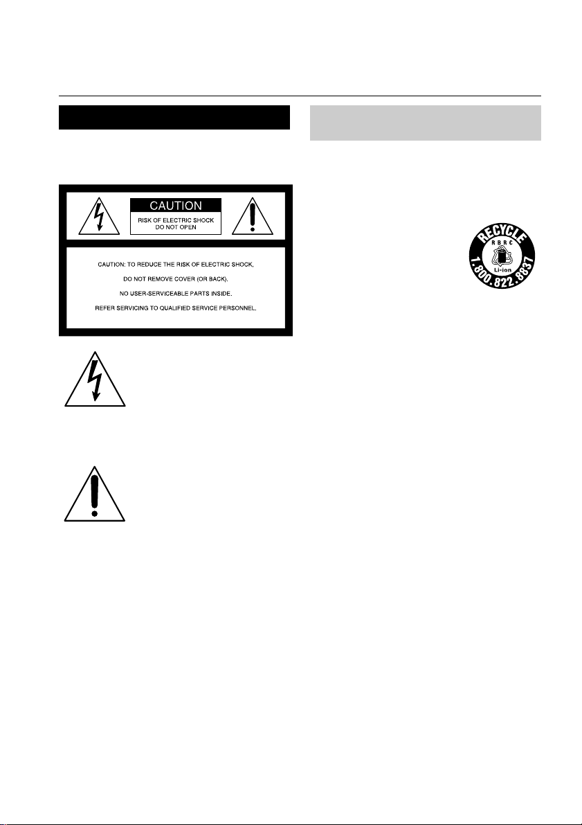
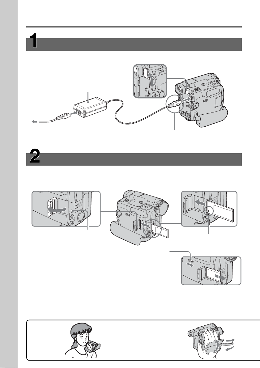
Connecting the power cord (p. 17)
Use the battery pack when using your camcorder outdoors (p. 16).
AC Adaptor (supplied)
Connect the plug with its v mark facing the
battery.
Open the DC IN
jack cover.
To eject the cassette
Follow the procedures above, and take out the cassette after the cassette compartment
opens completely in step 2.
Note
Do not press the cassette compartment down forcibly. Doing so may cause a
malfunction.
Inserting the cassette
1 Slide OPEN/ZEJECT
in the direction of
the arrow and open
the lid.
2 Push the center of the
cassette back to insert
the cassette. Insert the
cassette straight as far
as possible into the
cassette compartment
with the window
facing up.
3 Close the cassette
compartment by
pressing on the
cassette
compartment.
After the cassette
compartment goes
down completely,
close the lid until it
clicks.
1
2
3
4
Fastening the grip belt
Fasten the grip belt firmly.
How to hold
your camcorder
1
2
3
Quick Start Guide
9
Quick Start Guide
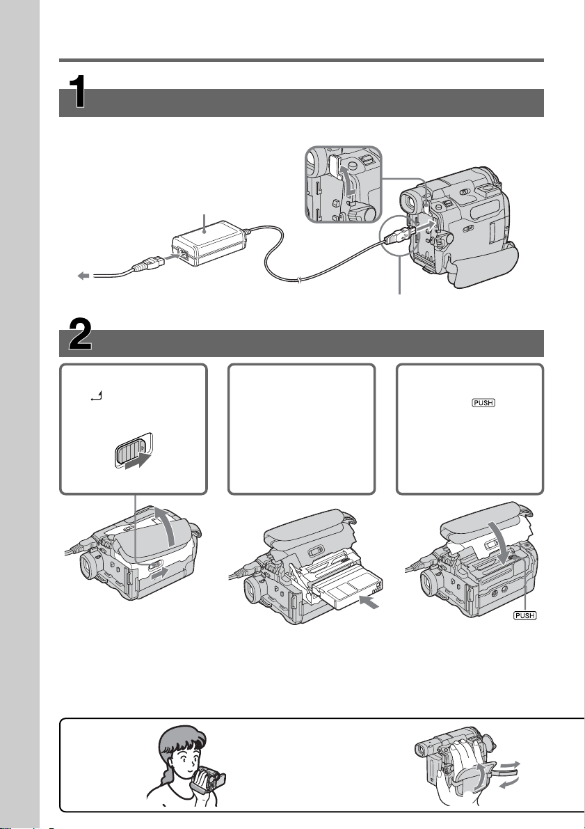
Recording a picture on the tape (p. 25)
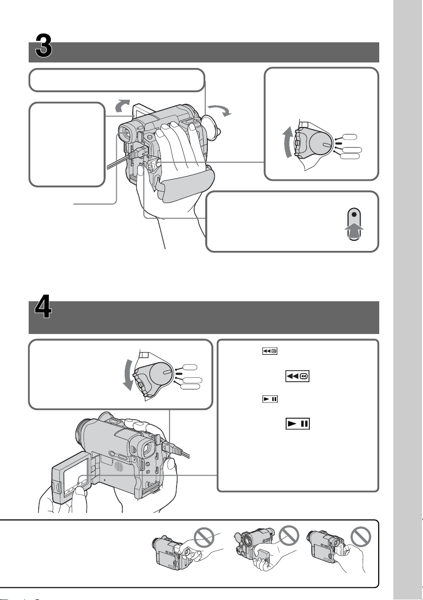
Monitoring the playback picture on the LCD
screen (p. 39)
When you purchase your camcorder, the clock setting is set to off. If you want to record the date
and time for a picture, set the clock setting before recording (p. 22).
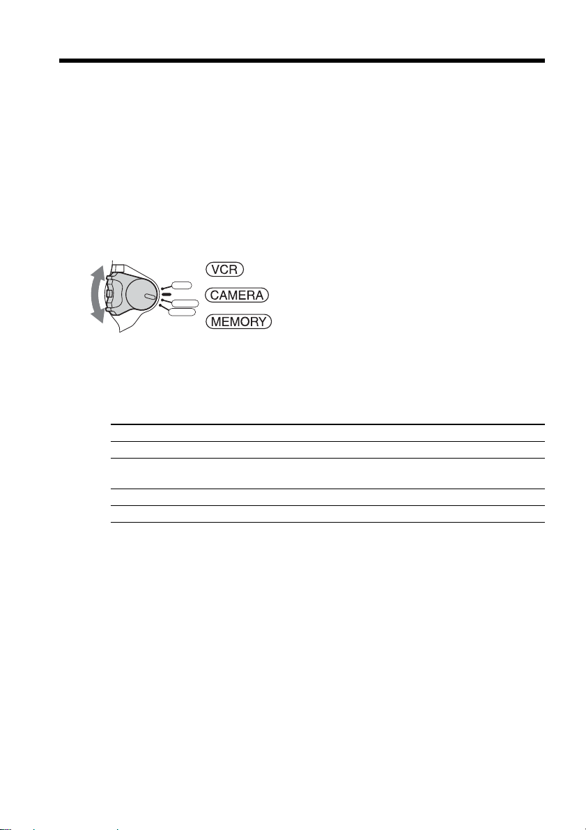
2Set the POWER switch
to CAMERA while
pressing the small
green button.
4Press START/STOP. Your
camcorder starts recording.
To stop recording, press
START/STOP again.
1Open the lens cap (p. 25).
3Press OPEN
to open the
LCD panel.
The picture
appears on
the screen.
Viewfinder
When the LCD panel is closed,
pull out the viewfinder and
look at the picture in it.
Adjust the viewfinder lens to
your eyesight (p. 31).
1Set the POWER
switch to VCR
while pressing the
small green button.
3Press of the touch panel to
start playback.
Note
When using the touch panel, press
operation buttons lightly with your
finger supporting the LCD panel from
the back side of it. Do not press the
LCD screen with sharp objects.
2Press of the touch panel to
rewind the tape.
Do not pick up your camcorder
by holding parts as illustrated.
Viewfinder LCD panel Battery pack
VCR
OFF
(
CHG
)
POWER
CAMERA
MEMORY
VCR
OFF
(
CHG
)
POWER
CAMERA
MEMORY
Quick Start Guide
10
Inserting the “Memory Stick” (p. 109)
Open the lid of the “Memory Stick” slot. Insert the “Memory Stick” in the “Memory Stick”
slot as far as it can go with the b mark facing down as illustrated, then close the lid.
While the access lamp is lit or flashing
Do not shake or strike your camcorder because your camcorder is reading the data from
the “Memory Stick” or recording the data on the “Memory Stick.” Do not turn the
power off, eject the “Memory Stick” or remove the battery pack. Otherwise, image data
breakdown may occur.
Quick Start Guide – Recording on “Memory Stick”
(DCR-TRV22/TRV33 only)
Connecting the power cord (p. 17)
Use the battery pack when using your camcorder outdoors (p. 16).
Open the DC IN
jack cover.
Connect the plug with its v
mark facing the battery.
AC Adaptor (supplied)
Access lamp
b mark
To eject the “Memory Stick,”
open the lid of the “Memory
Stick” slot, slide MEMORY
EJECT in the direction of the
arrow.
1
2
3
4
Fastening the grip belt
Fasten the grip belt firmly.
How to hold
your camcorder
1
2
3

Quick Start Guide
11
Recording still images on the “Memory Stick”
(p. 114)
Monitoring the playback still image on the LCD
screen (p. 135)
1Set the POWER
switch to MEMORY
while pressing the
small green button.
2Press PLAY. The last
recorded image is
displayed.
1Open the lens cap (p. 25).
5Press PHOTO deeply.
The image when you press
PHOTO deeply is recorded
on the "Memory Stick."
Viewfinder
When the LCD panel is closed,
pull out the viewfinder and look
at the picture in it.
Adjust the viewfinder lens to
your eyesight (p. 31).
3Press OPEN
to open the
LCD panel.
The picture
appears on
the screen.
2Set the POWER switch to
MEMORY while pressing
the small green button.
Make sure that the LOCK
switch is set to the left
(unlock) position.
4Press PHOTO lightly.
You can record when the
green z stops flashing
and remains lit.
Do not pick up your camcorder
by holding parts as illustrated.
Viewfinder LCD panel Battery pack
VCR
OFF
(
CHG
)
POWER
CAMERA
MEMORY
12
FINE
640
101
101
FINE
640
When you purchase your
camcorder, the clock setting is
set to off. If you want to
record the date and time for a
picture, set the clock setting
before recording (p. 22).
VCR
OFF
(
CHG
)
POWER
CAMERA
MEMORY
PLAY
12
— Getting Started —
Using this manual
The instructions in this manual are for the 3 models listed in the table below. Before you
start reading this manual and operating your camcorder, check the model number by
looking at the bottom of your camcorder. The DCR-TRV33 is the model used for
illustration purposes. Otherwise, the model name is indicated in the illustrations. Any
differences in operation are clearly indicated in the text, for example, “DCR-TRV33
only.”
As you read through this manual, buttons and settings on your camcorder are shown in
capital letters.
After “Advanced Recording Operations” section of this
manual, position of the POWER switch is shown by the icons
below.
: Set the POWER switch to VCR.
: Set the POWER switch to CAMERA.
: Set the POWER switch to MEMORY.
(DCR-TRV22/TRV33 only)
When you carry out an operation, you can hear a beep to indicate that the operation is
being carried out.
Types of differences
DCR- TRV19 TRV22 TRV33
Viewfinder B&W Color Color
MEMORY mark* — zz
(on the POWER switch)
AUDIO/VIDEO jack z** zz
S VIDEO jack z** zz
z Provided
— Not provided
* The models with MEMORY marked on the POWER switch is provided with
memory functions. See page 106 for details.
** Output only
VCR
OFF
(
CHG
)
POWER
CAMERA
MEMORY

13
Getting Started
Using this manual
Note on Cassette Memory
Your camcorder is based on the DV format. You can use only mini DV cassettes with
your camcorder. We recommend that you use a cassette with Cassette Memory .
Cassettes with Cassette Memory have the (Cassette Memory) mark.
Note on TV color systems
TV color systems differ depending on the country or area. To view your recordings on a
TV, you need an NTSC system-based TV.
Copyright precautions
Television programs, films, video tapes, and other materials may be copyrighted.
Unauthorized recording of such materials may be contrary to the copyright laws.
Note on connecting other equipment
When you connect your camcorder to other video equipment or a computer using the
USB cable or i.LINK cable, observe the shape of the jack.
If you forcibly insert the plug, the jack may be damaged and they may result in a
malfunction of your camcorder.
14
[a]
[b]
[c][d]
Using this manual
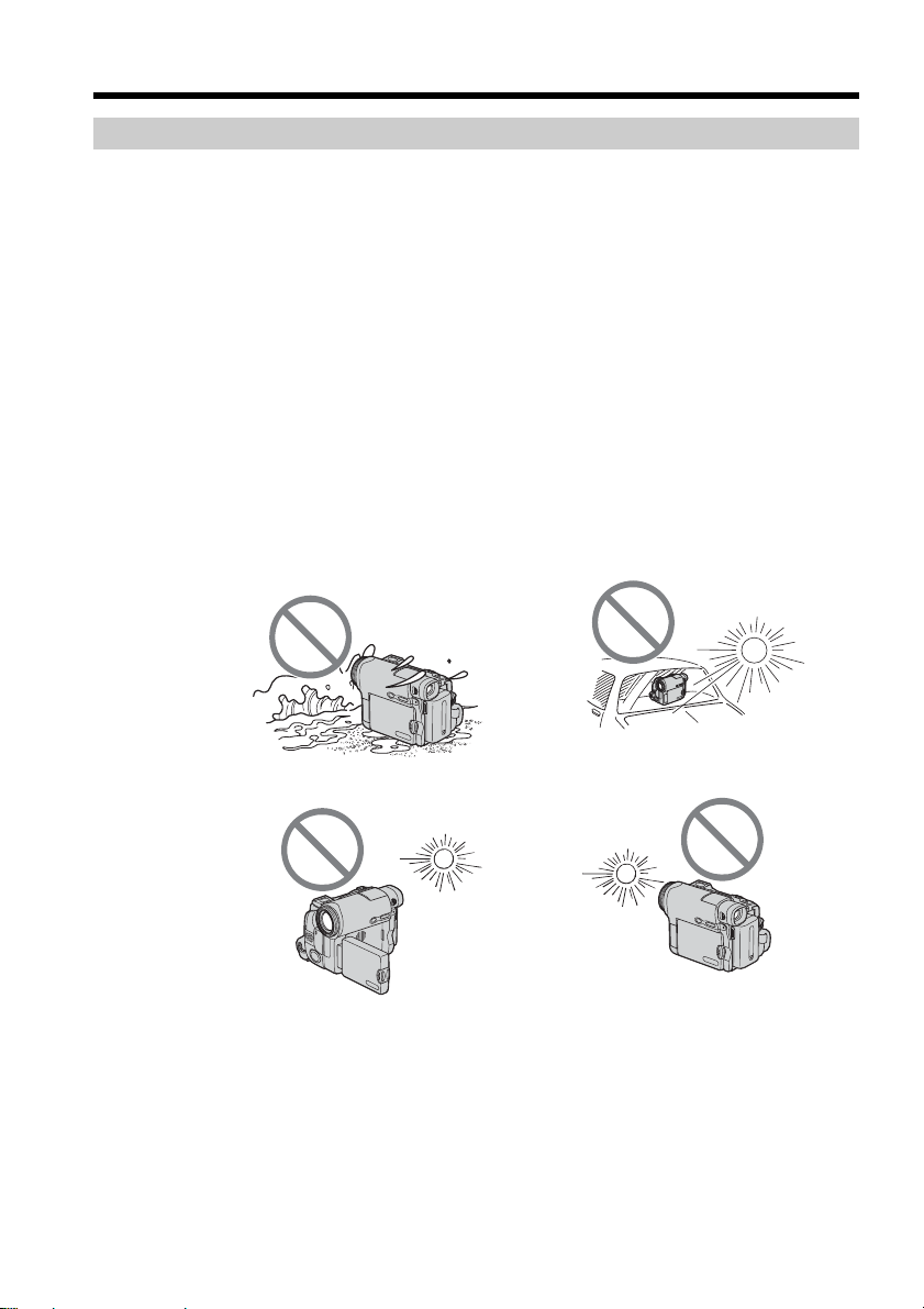
Precautions on camcorder care
Lens and LCD screen/finder (on mounted models only)
•The LCD screen and the finder are manufactured using extremely high-precision
technology, so over 99.99% of the pixels are operational for effective use.
However, there may be some tiny black points and/or bright points (white, red,
blue or green in color) that constantly appear on the LCD screen and the finder.
These points are normal in the manufacturing process and do not affect the
recording in any way.
•Do not let your camcorder get wet. Keep your camcorder away from rain and sea
water. Letting your camcorder get wet may cause your camcorder to malfunction.
Sometimes this malfunction cannot be repaired [a].
•Never leave your camcorder exposed to temperatures above 60°C (140°F), such as in a
car parked in the sun or under direct sunlight [b].
•Be careful when placing the camera near a window or outdoors. Exposing the LCD
screen, the finder or the lens to direct sunlight for long periods may cause
malfunctions [c].
•Do not directly shoot the sun. Doing so might cause your camcorder to malfunction.
Take pictures of the sun in low light conditions such as dusk [d].
15
Getting Started
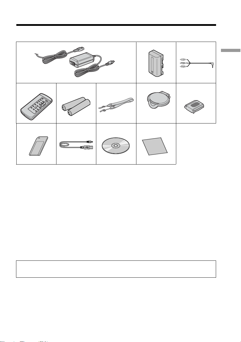
Checking supplied accessories
Make sure that the following accessories are supplied with your camcorder.
1 AC-L15A/L15B AC Adaptor (1), Power
cord (1) (p. 17)
2 NP-FM30 rechargeable battery pack
(1) (p. 16)
3 A/V connecting cable (1) (p. 44)
4 Wireless Remote Commander (1) (p.
75)
5 Size AA (R6) battery for Remote
Commander (2) (p. 217)
6 Shoulder strap (1)
Contents of the recording cannot be compensated if recording or playback is not made due to a
malfunction of the camcorder, storage media, etc.
7 Lens cap (1) (p. 213)
8 Shoe cover (1) (p. 98)
9 “Memory Stick” (1) (DCR-TRV22/
TRV33 only, p. 106)
0 USB cable (1) (p. 148)
qa CD-ROM (SPVD-010 USB Driver) (1)
(p. 153, 171)
qs Cleaning cloth (1) (p. 206)
9
1
4
q;
5
qa
6
2
7
3
8
qs
16
Step 1 Preparing the power source
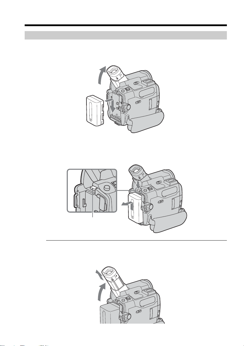
Installing the battery pack
(1) Lift up the viewfinder.
(2) Slide the battery pack down until it clicks.
To remove the battery pack
(1) Lift up the viewfinder.
(2) Slide the battery pack out in the direction of the arrow while pressing BATT
down.
If you use the viewfinder when a large capacity battery pack is installed
If you install the NP-FM70/QM71/QM71D/FM91/QM91/QM91D battery pack on your
camcorder, extend the viewfinder, and lift up the viewfinder to a comfortable angle.
BATT release
button
2
1
17
Getting Started
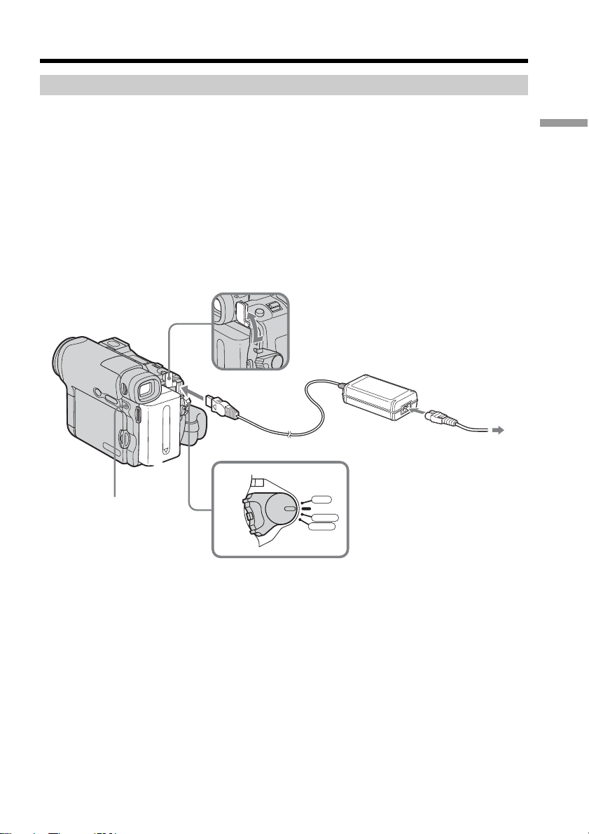
Charging the battery pack
Use the battery pack after charging it for your camcorder.
Your camcorder operates only with the “InfoLITHIUM” battery pack (M series).
See page 200 for details of “InfoLITHIUM” battery pack.
(1) Install the battery pack on your camcorder.
(2) Connect the AC Adaptor supplied with your camcorder to the DC IN jack with
the v mark on the DC plug facing the battery.
(3) Connect the power cord to the AC Adaptor.
(4) Connect the power cord to a wall outlet.
(5) Set the POWER switch to OFF (CHG).
The CHG lamp lights up when charging begins. After charging is completed,
the CHG lamp goes out (full charge).
After charging the battery pack
Disconnect the AC Adaptor from the DC IN jack on your camcorder.
Step 1 Preparing the power source
3
2
1
5
VCR
OFF
(
CHG
)
POWER
CAMERA
MEMORY
CHG lamp

18
Step 1 Preparing the power source
Note
Prevent metallic objects from coming into contact with the metal parts of the DC plug of
the AC Adaptor. This may cause a short-circuit, damaging the AC Adaptor.
When you use the AC Adaptor
Place the AC Adaptor near a wall outlet. While using the AC Adaptor, if any trouble
occurs with this unit, disconnect the plug from a wall outlet as soon as possible to cut
off the power.
Note on the CHG lamp
The CHG lamp flashes in the following cases:
– The battery pack is not properly installed.
– Something is wrong with the battery pack.
Charging time
Battery pack Full charge
NP-FM30 (supplied) 145
NP-FM50 150
NP-FM70 240
NP-QM71/QM71D 260
NP-FM91/QM91/QM91D 360
Approximate minutes at 25°C (77°F) to charge an empty battery pack.
The charging time may increase if the battery’s temperature is extremely high or low
because of the ambient temperature.

19
Getting Started
Step 1 Preparing the power source
Recording time
DCR-TRV19/TRV22
Recording with Recording with
Battery pack the viewfinder the LCD screen
Continuous Typical* Continuous Typical*
NP-FM30 (supplied) 125 65 90 45
NP-FM50 200 105 150 75
NP-FM70 415 215 310 160
NP-QM71/QM71D 485 255 365 190
NP-FM91/QM91/QM91D 725 380 550 290
DCR-TRV33
Recording with Recording with
Battery pack the viewfinder the LCD screen
Continuous Typical* Continuous Typical*
NP-FM30 (supplied) 90 50 70 35
NP-FM50 150 85 120 65
NP-FM70 310 175 250 140
NP-QM71/QM71D 365 205 290 165
NP-FM91/QM91/QM91D 550 310 445 250
Approximate minutes when you use a fully charged battery pack
* Approximate number of minutes when recording while you repeat recording start/
stop, zooming and turning the power on/off. The actual battery life may be shorter.
20
DSPL/BATT INFO
BATTERY INFO
BATTERY CHARGE LEVEL
REC TIME AVAILABLE
LCD SCREEN
VIEWFINDER
:
:
56
72
min
min
0% 50%
100%
BATTERY INFO
BATTERY CHARGE LEVEL
REC TIME AVAILABLE
LCD SCREEN
VIEWFINDER
:
:
70
90
min
min
0% 50% 100%
3
During charging
Fully charged
Playing time
DCR-TRV19/TRV22
Battery pack
Playing time on Playing time on with
the LCD panel the LCD screen closed
NP-FM30 (supplied) 100 150
NP-FM50 165 240
NP-FM70 345 495
NP-QM71/QM71D 400 580
NP-FM91/QM91/QM91D 605 865
DCR-TRV33
Battery pack
Playing time on Playing time with
the LCD panel the LCD screen closed
NP-FM30 (supplied) 100 135
NP-FM50 160 220
NP-FM70 335 450
NP-QM71/QM71D 390 530
NP-FM91/QM91/QM91D 585 785
Approximate minutes when you use a fully charged battery pack
Note
Approximate recording time and continuous playing time at 25°C (77°F). The battery
life will be shorter if you use your camcorder in a cold environment.
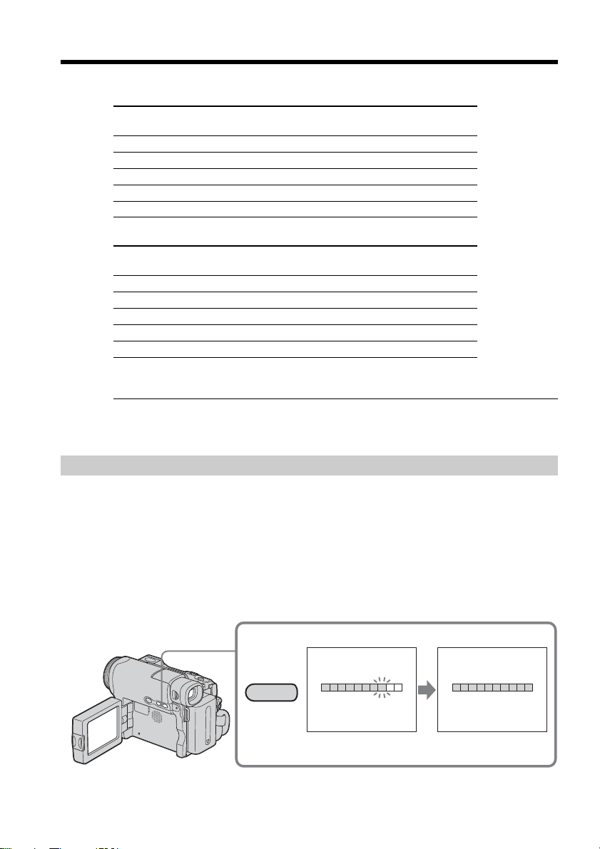
Checking status of battery pack – Battery Info
(1) Set the POWER switch to OFF (CHG).
(2) Press OPEN to open the LCD panel.
(3) Press DSPL/BATT INFO.
The battery charge level (the percentage of remaining battery time) and
remaining battery time when using the LCD screen or viewfinder are
displayed for about 7 seconds.
If you keep pressing DSPL/BATT INFO, the indicators will be displayed for
about 20 seconds.
Step 1 Preparing the power source

21
Getting Started
Notes
•The BATTERY INFO indicator may not be displayed in the following cases:
– The battery pack is not installed.
– Something is wrong with the battery pack.
– The battery is exhausted.
•The BATTERY INFO indicator will not appear when you press DISPLAY on the
Remote Commander when the POWER switch is set to OFF (CHG).
Battery Info
The number displayed as Battery Info is the approximate recording time.
While the remaining battery time is being calculated
“CALCULATING BATTERY INFO ...” is displayed.
If you press DSPL/BATT INFO with the LCD panel closed
The battery information appears on the viewfinder for about 7 seconds.
Connecting to a wall outlet
You can use your camcorder without worrying about the power shortage.
Connect the AC Adaptor in the same way as you would when charging the battery
pack.
PRECAUTION
The set is not disconnected from the AC power source (house current) as long as it is
connected to the wall outlet, even if the set itself has been turned off.
Notes
•The AC Adaptor can supply power from a wall outlet even if the battery pack is
attached to your camcorder.
•The DC IN jack has “source priority.” This means that the battery pack cannot supply
any power if the power cord is connected to the DC IN jack, even when the power
cord is not plugged into a wall outlet.
Step 1 Preparing the power source
22
Step 2 Setting the date and time
Set the date and time when you use your camcorder for the first time. The “CLOCK
SET” indicator will appear each time you set the POWER switch to CAMERA or
MEMORY (DCR-TRV22/TRV33 only) unless you set the date and time settings.
If you do not set the date and time, “--- -- ----” and “--:--:--” are recorded on the tape or
the “Memory Stick” (DCR-TRV22/TRV33 only) as the data code.
If you do not use your camcorder for about 4 months, the date and time settings may
be released (bars may appear) because the built-in rechargeable battery installed in your
camcorder will have been discharged (p. 207). In this case, charge the built-in
rechargeable battery, then set the year, the month, the day, the hour and the minute.
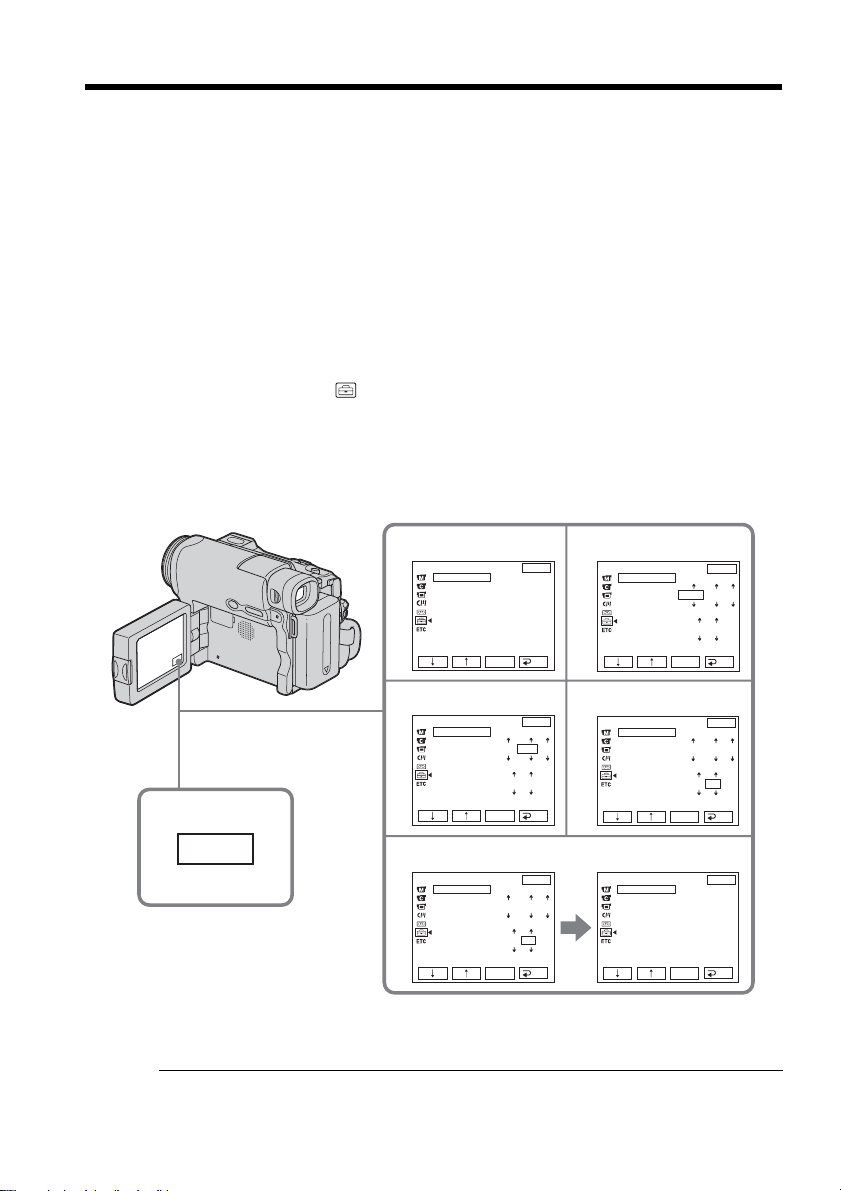
(1) Set the POWER switch to CAMERA or MEMORY (DCR-TRV22/TRV33 only).
(2) Press OPEN to open the LCD panel.
(3) Press FN (Function) to display PAGE1 (p. 23).
(4) Press MENU to display the menu.
(5) Press r/R to select
, then press EXEC.
(6) Press r/R to select CLOCK SET, then press EXEC.
(7) Press r/R to select a desired year, then press EXEC.
(8) Set the month, day and hour with the same procedure as step 7.
(9) Press r/R to set the minute, then press EXEC by the time signal. The clock
starts to move.
To return to FN (Function)
Press EXIT.
Note on the time indicator
The internal clock of your camcorder operates on a 12-hour cycle.
•12:00 AM stands for midnight.
•12:00 PM stands for noon.
3
FN
SETUP MENU
CLOCK SET
USB STREAM
LANGUAGE
DEMO MODE
EXIT
RET.
EXEC
––:––:––
5
9
6
7
8
SETUP MENU
CLOCK SET
USB STREAM
LANGUAGE
DEMO MODE
EXIT
RET.
EXEC
2003
JAN
1
12 00 AM
SETUP MENU
CLOCK SET
USB STREAM
LANGUAGE
DEMO MODE
EXIT
RET.
EXEC
2003
JAN
1
12 00 AM
SETUP MENU
CLOCK SET
USB STREAM
LANGUAGE
DEMO MODE
EXIT
RET.
EXEC
2003
JUL
4
5 00 PM
SETUP MENU
CLOCK SET
USB STREAM
LANGUAGE
DEMO MODE
EXIT
RET.
EXEC
JUL 4 2003
5:30:00
PM
SETUP MENU
CLOCK SET
USB STREAM
LANGUAGE
DEMO MODE
EXIT
RET.
EXEC
2003
JUL
4
5 30 PM
 Loading...