


 Loading...
Siemens Range LP
Conversion Manual
Operating, Care and Installation Instructions
Please read instructions before using.
Important: Save these instructions.
Guide de conversion au gaz propane (LP) pour les cuisinières Siemens
Instructions de fonctionnement, d’entretien et d’installation
Merci de lire les instructions avant d'utiliser.
Important : Conserver ces instructions.
Manual de conversión de gas propano (LP) para estufas de Siemens
Operación, cuidado e instrucciones para la instalación
Favor de leer las instrucciones antes de usar.
Importante: Guarde estas instrucciones.

Table of Contents
Safety . . . . . . . . . . . . . . . . . . . . . . . . . . . . . . . . . . . . . . . . . . . . . . . . . . . . . . . . . 1
IMPORTANT SAFETY INSTRUCTIONS . . . . . . . . . . . . . . . . . . . . . . . . . . . . . . . . . . . . . . . . . . . . . . . . . . 1
Conversion . . . . . . . . . . . . . . . . . . . . . . . . . . . . . . . . . . . . . . . . . . . . . . . . . . . . . 2
Before You Begin . . . . . . . . . . . . . . . . . . . . . . . . . . . . . . . . . . . . . . . . . . . . . . . . . . . . . . . . . . . . . . . . . . . . |
2 |
Procedure . . . . . . . . . . . . . . . . . . . . . . . . . . . . . . . . . . . . . . . . . . . . . . . . . . . . . . . . . . . . . . . . . . . . . . . . . . |
3 |
Test the Installation . . . . . . . . . . . . . . . . . . . . . . . . . . . . . . . . . . . . . . . . . . . . . . . . . . . . . . . . . . . . . . . . . . |
6 |
Service . . . . . . . . . . . . . . . . . . . . . . . . . . . . . . . . . . . . . . . . . . . . . . . . . . . . . . . 10
Before Calling Service . . . . . . . . . . . . . . . . . . . . . . . . . . . . . . . . . . . . . . . . . . . . . . . . . . . . . . . . . . . . . . . 10
Questions?
866-44SIEMENS (447-4363) www.siemens-home.com
5551 McFadden Ave.
Huntington Beach, CA 92649
We look forward to hearing from you!
Safety
IMPORTANT SAFETY INSTRUCTIONS
Important Safety
Instructions
•Please read Installation Instructions before beginning the conversion.
•Please read all instructions before proceeding. Save the natural gas parts for possible conversion from LP back to natural gas in the future.
•This kit is used to convert dual fuel ranges and gas ranges from natural gas operation to propane (LP) gas operation. Only ranges manufactured by BSH Home Appliances can be converted using this kit.
CAUTION:
When connecting the unit to the propane gas, make certain the propane gas tank is equipped with its own high pressure regulator. In addition, the range has its own pressure regulator. Verify that it is installed for the appropriate gas supply.
•The maximum gas pressure to this appliance is not to exceed 14.0 inches water column from the propane gas tank regulator.
•The following must be met when testing supply piping system:
a)The appliance and its individual shut-off valve must be disconnected from the gas supply piping system at test pressures in excess of 1/2 psig (3.5 kPa).
b)The appliance must be isolated from the gas supply piping system by closing its individual manual shut-off valve during any pressure testing of the gas supply piping system at test pressures equal to or less than 1/2 psig (3.5 kPa).
WARNING:
This conversion kit shall be installed by a qualified service agency in accordance with the manufacturer's instructions
and all applicable codes and requirements of the authority having jurisdiction. If the information in these instructions is not followed exactly, a fire, explosion or production of carbon monoxide may result causing property damage, personal injury or loss of life. The qualified service agency is responsible for the proper installation of this kit. The installation is not proper and complete until the operation of the converted appliance is checked as specified in the manufacturer's instructions supplied with the kit.
•For Massachusetts Installations:
1)Installation must be performed by a qualified or licensed contractor, plumber or gas fitter qualified or licensed by the state, province or region where this appliance is being installed.
2)Shut-off valve must be a "T" handle gas cock.
3)Flexible gas connector must not be longer than 36 inches.
•High Altitude Installation Note: This range is CSA certified for safe operation up to an altitude of 10,000 ft. without any modifications (except LP conversion, when applicable).
English 1

Conversion
Before You Begin
Tools and Parts Needed
Parts Included
General Information
•7 mm Socket Driver w/ 3" extension
•Torx (T20) head screwdriver
•Adjustable Wrench
•Flathead Screwdriver (1/8" or smaller)
•Phillips Head Screwdriver
•Conversion Kit Instructions
•Conversion Sticker
•4 LP Orifices
Always Provide Adequate Gas
Supply
This appliance is shipped from the factory for use with natural gas. Use this kit to convert the appliance for LP gas use if necessary. Observe the following:
Be sure the range is converted for use with the appropriate gas before using it.
This appliance is designed to operate at a pressure of 10" of water column when used with LP gas.
When checking for proper operation of the regulator, the inlet pressure must be at least 1" greater than the operating (manifold) pressure above. When converting for LP gas use, the pressure supplied to the regulator must be between 11" and 14" of water column. See “Convert Pressure Regulator from 5" W.C. to 10" W.C.” on page 3.
The pressure regulator located in the inlet of the range manifold must remain in the supply line.
Use a flexible metal appliance connector or rigid pipe to connect the Range to the gas supply. The connector should have an I.D. of 1/2" and be 5' in length (Exception: Maximum connector length in Massachusetts installations is 3'). In Canada, the connector must be single wall metal and not longer than 6'.
Preparation |
CAUTION: |
|
|
Turn off Gas and Electricity. |
|
|
Before proceeding with the conversion; shut off the gas supply to the appliance |
|
|
prior to disconnecting the electrical power. |
|
|
1. |
Turn all control knobs to the "OFF" position. |
|
2. |
Shut off the outside propane tank gas valve to the range. |
|
3. |
Remove range power cord from electrical outlet or turn breaker off at breaker |
|
|
box. |
English 2
Conversion
Procedure
Convert Pressure Regulator from 5" W.C. to 10" W.C.
1.Remove Warming Drawer; Pull drawer out until stop is reached. Facing the range, push clip on left side up and clip on right side down. Pull drawer the rest of the way out.
2.Remove cover plate from interior back wall by removing single screw on left side of panel. Use a Torx T-20 head screwdriver.
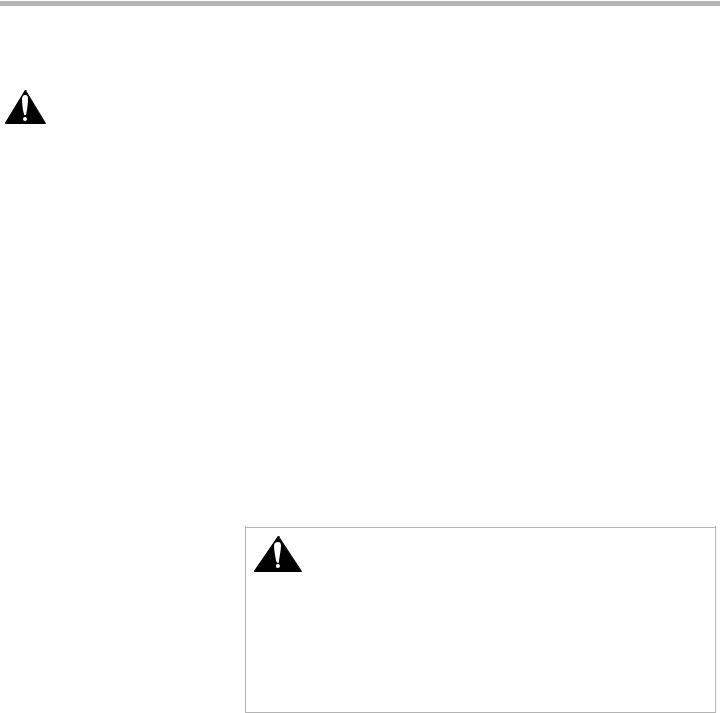
3.Remove the hexagon cap from the top of the regulator with an adjustable wrench.
4.Pop out the plastic stem in the cap and turn it over pressing it firmly in place so that the letters "LP" (rather than "NAT") are seen upright in the stem.
5.Replace the cap and button assembly into the top of the regulator sealing it firmly. Make certain spring is still in place. See Figure 1: Pressure Regulator. DO NOT OVER TIGHTEN.
Pin
Position
for Nat.
Gas
Hex 
Cap
NAT |
NA |
Pin |
T |
|
Pin Position
for Propane
Hex


 Cap
Cap
Pin
 LP
LP
LP

 Spring
PRESSURE REGULATOR VIEW
Figure 1: Pressure Regulator
6.Fill out and affix the CONVERSION STICKER on the back side of the cover plate so that it appears on the back side of range next to the regulator.
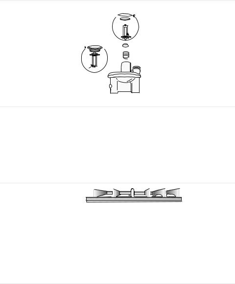
Replace Cooktop Orifices 1. Remove Grates, Burner Caps and Burner Bases.
Unscrew two (2) T20 screws inside each base and remove burner bases. Reinsert screws in jet holder to hold tubing assembly in place.
Burner Grate
Burner Cap
Burner Base
Orifice
Ignitor
Figure 2: Cooktop Orifice
3.Remove Natural Gas Cooktop Orifices.
Insert the socket driver with 3" minimum extension into the jet holders to remove existing orifices. Set natural gas orifices aside.
4.Assemble LP Cooktop Orifices.
Place in cooktop exactly as laid out in the orifice card. If the orifices become
English 3
Convert Cooktop Valves for Propane Use
Conversion
separated from the card, placement can be determined by matching the number and/or color on the orifice with the placement specifications displayed in the chart on the card.
5.Place the new orifice into the socket then insert each orifice into its respective threaded hole in the jet holder. Tighten until the orifice stops turning. DO NOT OVER TIGHTEN.
6.Remove screws to replace burner base, burner cap and burner grate. Replace screws.
Note:
Burner cap must be properly positioned on burner base for burner to light.
7.Place natural gas orifices in back of card for future conversion back to natural gas.
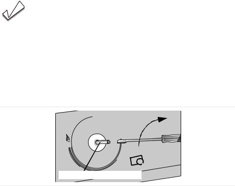
1.Verify that all knobs are in the OFF position.
2.Remove knobs (pull straight out).
3.Insert 1/8” (or smaller) flat head screwdriver into shaft and turn bypass screw clockwise until it stops (bypass screw is inside shaft). DO NOT OVERTIGHTEN.
Adjust Broil Burner
Orifice
OFF
SIM
HI
LO
Bypass Screw Inside Shaft
Figure 4: Cooktop Valve Conversion
5. Replace knobs.
If your range is dual fuel your conversion is complete. Replace the cover plate and warming drawer and proceed to “Test the Installation” on page 6.
For gas range conversions, continue to next step.
1.Remove oven door (see section "Removing Oven Door" in Use and Care manual).
2.Remove Broil Burner Assembly. The broil burner assembly is attached to the top of the oven cavity with 7 screws. Remove screws and gently pull broil burner assembly straight out being careful not to detach electrical wires. Place broil burner against back wall of oven cavity.
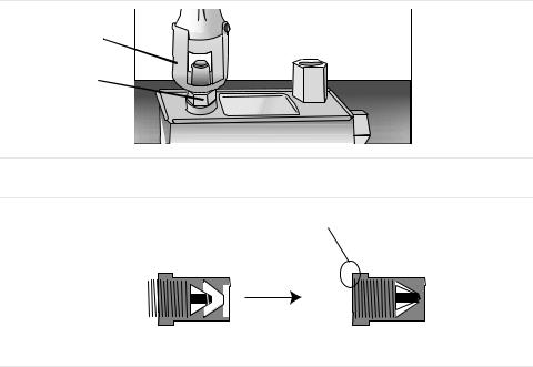
3.Adjust Broil Orifice. The orifice is located behind the broil burner in the back oven wall. See Figure 5: Broil Orifice Conversion. Use a 1/2" deep socket
English 4

Conversion
driver with 3" minimum extension to turn orifice clockwise until it stops (2- 2 1/ 2 turns). DO NOT OVERTIGHTEN.
CAUTION:
DO NOT overtighten the broil burner orifice. Overtightening may result in damage to the pin inside the orifice. This affects cooking
performance. It could cause inconsistent flames and unintentional release of carbon monoxide.
Adjust Bake Burner
Orifice
Broil Orifice
Figure 4: Broil Orifice
Tightened, but not fully seated
|
|
|
|
|
|
|
|
|
|
|
|
|
|
|
|
|
|
|
|
|
|
|
|
|
|
|
|
|
|
|
|
|
|
|
|
|
|
|
|
|
|
|
|
|
|
|
|
|
|
|
|
|
|
|
|
|
|
|
|
|
|
|
|
|
|
|
|
|
|
|
|
|
|
|
|
|
|
Natural Gas Setting |
LP Gas Setting |
|||||||||||
|
|
|
|
|
|
|
|
|
|
|
|
|
|
|
|
|
|
|
|
|
|
Figure 5: Broil Orifice Conversion |
|||
6.Replace Broil Assembly. Replace broil assembly being careful to feed all wires through back wall of oven. Reinsert all 7 screws.
Note:
The air shutter on the broil burner fits over the orifice when installed correctly.
The bake burner orifice is located below the air shutter. See Figure 2: Bake Orifice. Reach it through the access hole in the interior back panel of the warming drawer cavity.
English 5
Conversion
1.Use a 1/2" wrench to turn orifice clockwise until it stops (2 1/2 - 3 turns). Unlike the broil burner orifice, the bake burner orifice should be tightened as far as it will go in order to ensure that complete conversion has occurred.
Air Shutter
Bake Orifice
Figure 2: Bake Orifice
Fully seated
|
|
|
|
|
|
|
|
|
|
|
|
|
|
|
|
|
|
|
|
|
|
|
|
|
|
|
|
|
|
|
|
|
|
|
|
|
|
|
|
|
|
|
|
|
|
|
|
|
|
|
|
|
|
|
|
|
|
|
|
|
|
|
|
|
|
|
|
|
|
|
|
|
|
|
|
|
|
|
|
|
|
|
|
Natural Gas Setting |
LP Gas Setting |
||||||||||||
Figure 3: Bake Orifice Conversion
Test the Installation
Test for Gas Leaks |
Leak testing is to be conducted by the installer according to the instructions given |
|
in this section. |
Apply Leak Detection Fluid |
Turn on Gas. Apply a non-corrosive leak detection fluid to all joints and fittings in |
|
the gas connection between the shutoff valve and the range. Include gas fittings |
|
and joints in the range if connections may have been disturbed during installation. |
|
Bubbles appearing around fittings and connections indicate a leak. |
|
If a leak appears, turn off supply line gas shutoff valve and tighten connections. |
|
Retest for leaks by turning on the supply line gas shutoff valve. When leak check |
|
is complete (no bubbles appear), test is complete. Wipe off all detection fluid resi- |
|
due. |
|
CAUTION: |
|
Never check for leaks with a flame. |
|
Do not continue to the next step until all leaks are eliminated. |
Test Electric Ignition |
Turn on power at breaker. |
|
CAUTION: |
|
If the display flashes and beeps, the polarity of the wiring may be reversed. |
|
Reversed polarity can damage the range and can result in electrical shock haz- |
|
ard. Immediately switch off power at the breaker and return to installation instruc- |
|
tions. |
Test Cooktop Burners: |
Each burner must be tested for proper lighting, proper flame characteristics on the |
|
low setting and proper flame characteristics on the high setting. |
English 6 |
|
Conversion
Test for proper ignition:
1.Push down and turn the knob to ignition symbol.
2.Verify that the ignitor/spark module clicks.
3.Once the air has been purged from the supply lines, verify that the burner lights within four (4) seconds. After burner lights, turn knob to the OFF position.
4.Test each rangetop burner in this fashion. Call Service if any of the burners do not light.
Test flame characteristics on the low setting:
1.Push in and turn the knob to the ignition symbol until the burner ignites.
2.Turn knob to the low setting.
3.Verify that the burner maintains a minimum, steady, flame without going out. The flame should not lift or blow off of the burner. It should carry over, or surround, the entire burner.
4.Verify that the flame is the right color. It should be blue with an inner and outer cone. See Figure 6: Checking Flame Characteristics for more information.
5.Test each rangetop burner in this fashion. If any flame goes out, does not carry over properly or is too large, contact service.
Test flame characteristics on the high setting:
1.Push in and turn the knob to the ignitor symbol until the burner ignites.
2.Turn knob to the high setting.
3.Verify that the burner maintains a steady flame. The flame should not lift or blow off of the burner. It should carry over, or surround, the entire burner.
4.Verify that the flame is the right color. It should be blue with an inner and outer cone. See Figure 6: Checking Flame Characteristics for more information.
5.Test each rangetop burner in this fashion.
Yellow Flames:
Further adjustment is required.
Yellow Tips on Outer Cones:
Normal for LP Gas.
Soft Blue Flames:
Normal for Natural Gas.
If the flame is completely or mostly yellow, verify that the regulator is set for the correct fuel. After adjustment, retest.
Some yellow streaking is normal during the initial start-up. Allow unit to operat 4-5 minutes and re-evaluate.
Figure 6: Checking Flame Characteristics
If any flame does not carry over properly, adjust the bypass jet. Return to “Convert Cooktop Valves for Propane Use” on page 4. If any flame burns yellow, contact Service.
Dual Fuel appliance installation is complete when correct color, carryover and size are verified on each cooktop burner.
For gas appliances, continue to “Test Broil Burner” on page 8.
English 7

|
Conversion |
Test Broil Burner |
|
Test Ignition |
Set cooking mode to Hi Broil. The burner will ignite after 30-75 seconds. |
Test Flame |
Verify that flame characteristics are as shown in Figure 6: Checking Flame Char- |
|
acteristics. If flame characteristics are not consistent with those in the graphic |
|
above, adjust the flame as described below. Otherwise, continue to “Test Bake |
|
Burner”. |
Adjust Broil Flame (if necessary)
Adjust the air shutter to alter the flame characteristics. The air shutter is located on the back end of the broil burner.
1.Loosen screw and turn shutter. Close the shutter if the flame is lifting or blowing or not carrying over; Open the shutter if it is too yellow. See Figure 6: Checking Flame Characteristics. Tighten screw.
Screw
More Open: |
Air |
Shutter |
|
Less Yellow Flame |
|
More Closed:
Less Blue Flame
More Carryover
Less Lifting or Blowing
|
Figure 2: Broil Burner Air Shutter |
Test Bake Burner |
|
Test Ignition |
Set the oven to bake at 350° F. After 30-75 seconds, the burner will ignite. The |
|
burner will stay lit until the 350° F is reached and then shut off. From this point for- |
|
ward, the burner will cycle on and off to maintain the temperature. |
Test Flame |
Verify that flame characteristics are as shown in Figure 6: Checking Flame Char- |
|
acteristics. If flame characteristics are not consistent with those in the graphic |
|
above, adjust flame as described below. |
Adjust Bake Flame (if necessary)
Adjust the air shutter to alter the flame characteristics. The oven burner air shutter is located to the left of the oven regulator. Reach it through the access hole in the interior back panel of the warming drawer.
English 8
Loading...