


XG-NV5XU
NOTE TO SERVICE |
|
PERSONNEL |
|
c |
|
UV- |
PRECAUTION |
RADIATION |
|
‘//////////////‘///’ |
|
The light source, metal halide lamp, in the LCD |
|
projector emits small amounts of UV-Radiation. |
|
AVOID DIRECT EYE AND SKIN EXPOSURE. |
|
To ensure safety please adhere to the following: |
|
1.Be sure to wear sun-glasses when servicing the oroiector with the lame
iur;ed “on” and the top enclosure removed.
2. |
Do not operate the lamp outside of the lamp housing. |
3. |
Do |
not |
operate |
for more than |
2 |
hours with the |
|
enclosure |
removed. |
|
|
||
NOTE POUR LE PERSONNEL |
|||||||||
D’ENTRETIEN |
|
|
|
|
|||||
;////////‘////////// |
|
|
|
|
|||||
PRECAUTION |
POUR LES RADIATIONS |
UV |
|||||||
4 |
|
|
|
|
|
|
|
|
|
La source de lumi&re, la lampe metal halide, dans le |
|||||||||
projecteur |
LCD |
dmet de |
petites |
quantitbs |
de |
||||
radiation |
UV. |
|
|
|
|
|
|||
EVITEZ |
TOUTE |
EXPOSITION |
|
DIRECTE |
|
||||
DES YEUX |
ET DE LA PEAU. |
|
|
|
|||||
Pour votre s6curit6, nous vous prions de respecter |
|||||||||
les points suivants: |
|
|
|
|
|||||
1. |
Toujours |
porter |
des lunettes |
de |
soleil lors |
d’un |
|||
|
entretien du projecteur |
|
|
|
|
||||
|
avec |
la lampe allumee |
|
-7 |
|
|
|||
|
et le |
haut |
du coffret retirb. |
|
|
|
|||
|
|
|
/ |
|
|||||
|
|
|
|
|
|
|
|
|
|
|
|
|
|
|
|
* |
|
|
|
2. |
Ne pas |
faire fonctionner |
la lampe |
g I’ext&ieur |
du |
||||
|
boitier de |
lampe. |
|
|
|
|
|
||
3. |
Ne pas |
faire fonctionner plus de |
2 |
heures avec |
le |
|
coffret |
retirt?. |
|
|
|
UV-Radiation and |
Medium |
Pressure |
Lamp Precautions |
|
|
1. Be sure to disconnect |
the AC plug |
when replacing |
the lamp. |
|
|
2.Allow one hour for the unit to cool down before servicing.
3.Replace only with same type lamp. Type
|
CLMPFOOSDE05 |
or BQC- |
|
|
rated 65Vl |
||||||
|
15ow. |
|
|
|
|
XGNV5XU/l |
|||||
|
|
|
|
|
|
|
|
|
|
|
|
4. |
The lamp emits small |
amounts |
of UV- |
|
avoid |
||||||
|
direct-eye |
contact. |
|
|
|
|
Radiation, |
||||
|
|
|
|
|
|
|
|
|
|||
5. |
The medium |
pressure lamp |
involves |
a |
risk |
of |
|||||
|
explosion. |
Be |
sure |
to |
follow |
installation |
instructions |
||||
|
described |
below and |
|
handle |
the |
lamp with care. |
|
||||
Prbcautions |
pour les |
radiations |
UV |
|||
et la lampe |
moyenne |
pression |
|
|
||
1. Toujours debrancher |
la |
fiche |
AC |
lors |
du |
|
remplacement |
de la lampe. |
|
|
|
|
|
2.Laisser I’unit6 refroidir pendant une heure avant de proceder & I’entretien.
3. |
Ne remplacer |
qu’avec |
une lampe |
du meme |
type. |
|||
|
Type |
CLMPF0055DE05 |
or |
BQC-XGNV5XU/l, |
||||
|
caracteristique |
65V/15OW. |
|
|
|
|||
4. |
La lampe |
kmet |
de petites quantites |
de radiation |
UV- |
|||
|
eviter |
tout |
contact direct |
avec |
les yeux. |
|
||
5.La lampe moyenne pression implique un risque d’explosion. Toujours suivre les instructions
d’installation |
d&rites |
ci-dessous |
et manipuler |
la |
lampe avec |
soin. |
|
|
|
4

XG-NV5XU |
|
|
|
|
|
|
|
|
|
|
|
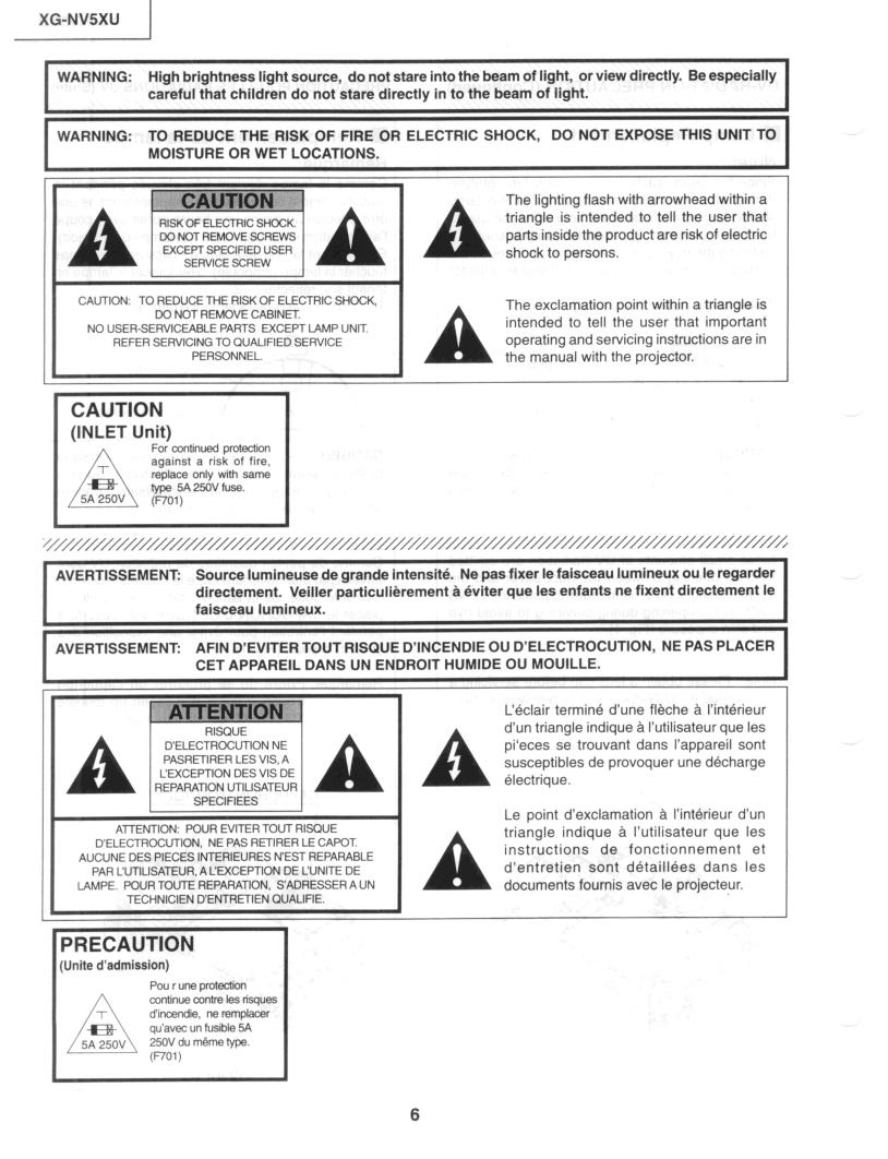
WARNING: |
High brightness light |
source, |
do not stare |
|
|
I |
|||||
into the beam of light, or view directly. |
Be especially |
||||||||||
|
careful that |
|
|
||||||||
|
children do |
not |
stare |
directly |
in to the beam |
of light. |
|
||||
WARNING: |
TO REDUCE |
THE |
RISK |
OF FIRE |
OR ELECTRIC SHOCK, |
DO NOT EXPOSE |
THIS UNIT TO |
||||
|
MOISTURE |
|
|||||||||
I |
OR WET LOCATIONS. |
|
|
|
|
||||||
|
|
|
|
|
|
|
|
|
|
||
A
The lighting |
flash with arrowhead |
within |
a |
|||
triangle |
is |
intended |
to |
tell the |
user that |
|
parts inside |
the product |
are risk of electric |
||||
shock |
to persons. |
|
|
|
|
|
CAUTION: TO REDUCE THE RISK OF ELECTRIC SHOCK, |
|
DO NOT REMOVE CABINET. |
|
NO USER- |
PARTS EXCEPT LAMP UNIT. |
SERVICEABLE |
|
REFER SERVICING |
TO QUALIFIED SERVICE |
PERSONNEL. |
|
c
|
The exclamation |
point |
within |
a triangle |
is |
|||
|
intended |
to |
tell |
the |
user that important |
|||
|
operating |
and servicing |
instructions are in |
|||||
A |
the manual |
with |
the |
projector. |
|
|
||
CAUTION |
|
|
(INLET Unit) |
|
|
For continued protection |
||
against |
a risk of |
fire, |
replace |
only with |
same |
type 5A 250V fuse. |
||
(F-W |
|
|
v rAVERTISSEMENT:
Source |
lumineuse de grande intensite. |
Ne pas fixer |
le faisceau |
lumineux |
ou le regarder |
|
||
|
|
|||||||
directement. Veiller |
particulibrement |
a eviter que |
les enfants |
ne fixent |
directement |
le |
I |
|
|
|
|||||||
faisceau lumineux. . |
|
|
|
|
|
|
||
I I
AVERTISSEMENT:
AFIN |
D’EVITER |
TOUT RISQUE D’INCENDIE OU D’ELECTROCUTION, |
NE PAS PLACER |
|||||
|
||||||||
CET APPAREIL |
DANS UN ENDROIT HUMIDE OU MOUILLE. |
|
|
|
I |
|||
|
|
|
|
|
|
|
|
1 |
|
|
C&lair |
termine d’une |
fleche a |
I’interieur |
|||
|
|
d’un triangle |
indique |
a i’utilisateur |
que les |
|||
|
|
pi‘eces |
se |
trouvant |
dans |
I’appareil sont |
||
|
|
susceptibles |
de provoquer |
une decharge |
||||
|
|
A electrique. |
|
|
|
|
|
|
ATTENTION: POUR EVITER TOUT RISQUE |
||
D’ELECTROCUTION, |
NE PAS RETIRER LE CAPOT |
|
AUCUNE DES PIECES INTERIEURES |
NEST REPARABLE |
|
PAR CUTILISATEUR, A CEXCEPTION DE CUNITE DE |
||
LAMPE. POUR TOUTE REPARATION, |
S’ADRESSER A UN |
|
TECHNICIEN |
D’ENTRETIEN |
QUALIFIE. |
|
Le point |
d’exclamation |
A I’interieur |
d’un |
||||
|
triangle |
indique |
a |
I’utilisateur |
que |
les |
||
|
instructions |
de |
|
fonctionnement |
et |
|||
A |
d’entretien |
|
sont |
|
detaillees |
dans |
les |
|
documents |
fournis |
|
avec |
le projecteur. |
|
|||
PRECAUTION |
|
|
(Unite d’admission) |
|
|
Pou rune |
protection |
|
continue contre les rfsques |
||
d’incendie, |
ne remplacer |
|
qu’avec un fusible 5A |
||
250V du mbme type. |
||
(not |
1 |
|
6


XG-NVSXU |
1 |
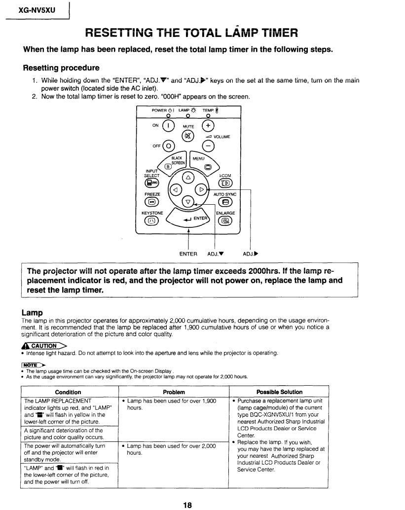
Operating the Wireless Mouse Remote Control
“Power” Remote Control
MUTE button |
|
|
|
POWER buttons |
(ON/OFF) |
||
BLACK SCREEN/TOOLS button |
|||
RIGHT-CLICK/ENTER |
button |
||
INPUT button |
|
|
|
FREEZE button |
|
|
|
KEYSTONE button |
|
||
MOUSE/ADJUSTMENT |
switch |
||
TRANSMISSION |
indicator |
||
VOLUME buttons |
(+/-I |
|
|
LASER POINTER/MENU button |
|||
MOUSE/ADJUSTMENT |
buttons |
||
IrCOM button |
|
|
|
AUTO SYNC button |
|
||
ENLARGE button |
|
|
|
BACKLIGHT button |
|
||
MAIN POWER switch |
|
||
LEFT-CLICK (BACK) button |
|||
Remote control |
signal |
transmitter |
|
Laser pointer window |
|
||
MOUSE signal |
transmitter |
||
MOUSE button |
|
|
|
RIGHT-CLICK |
button |
|
|
LEFT-CLICK button |
|
||
(A/V/4/F)
Simple Presentation Remote Control
8


XG-NV5XU |
) |
Dimensions |
|
3 %e(84) |
3 % (84) 3/d( |
5% (22)1 |
I |
|
|
|
F |
Ez =.
5
9 “+z (243.5) cl
’ |
/4((25):- |
* |
i_- T/16(11I |
0
0
Units: inches (mm)
12

1 |
XG-NVSXU |
|
|
|
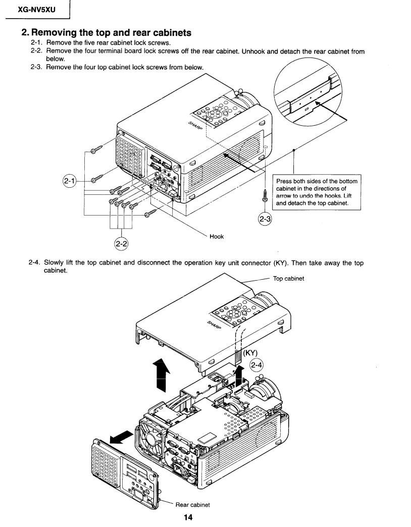
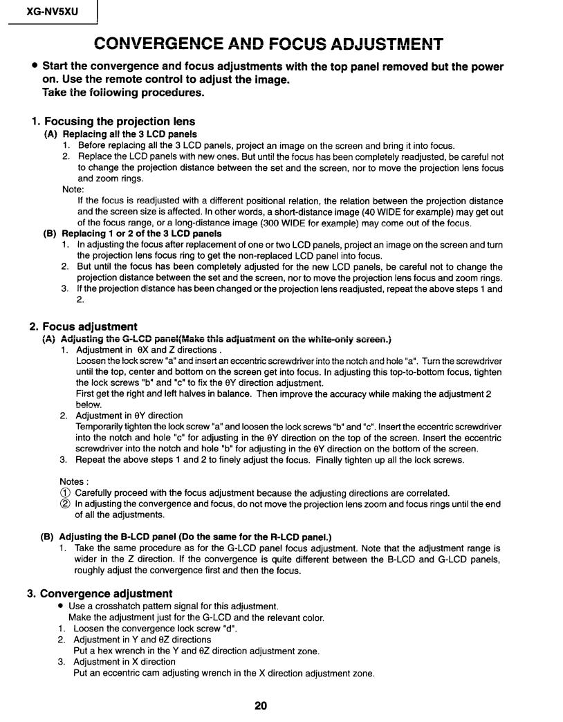
REMOVING |
OF MAJOR PARTS |
||
I. Removing the Intake cover and lamp unit |
|
|||||
l-l. |
Detach |
the Intake |
cover. |
|
|
|
l-2. |
Loosen |
the lamp cover screw and draw |
out the lamp cover in the direction |
of arrow (toward yourself). |
||
l-3. |
||||||
Remove |
the two |
lamp unit lock screws. |
Detach the lamp unit. |
|
||
-on spring
Intake
Lamp cover
Note: |
|
|
|
|
|
When |
replacing |
the lamp, |
make |
sure |
|
that there is a clearance |
of over |
|
|||
8mm between |
the terminal |
and |
the |
||
lamp snap-on spring (and |
other |
|
|||
metallic |
parts). |
|
|
|
|
13

|
|
|
|
|
|
|
|
|
|
I |
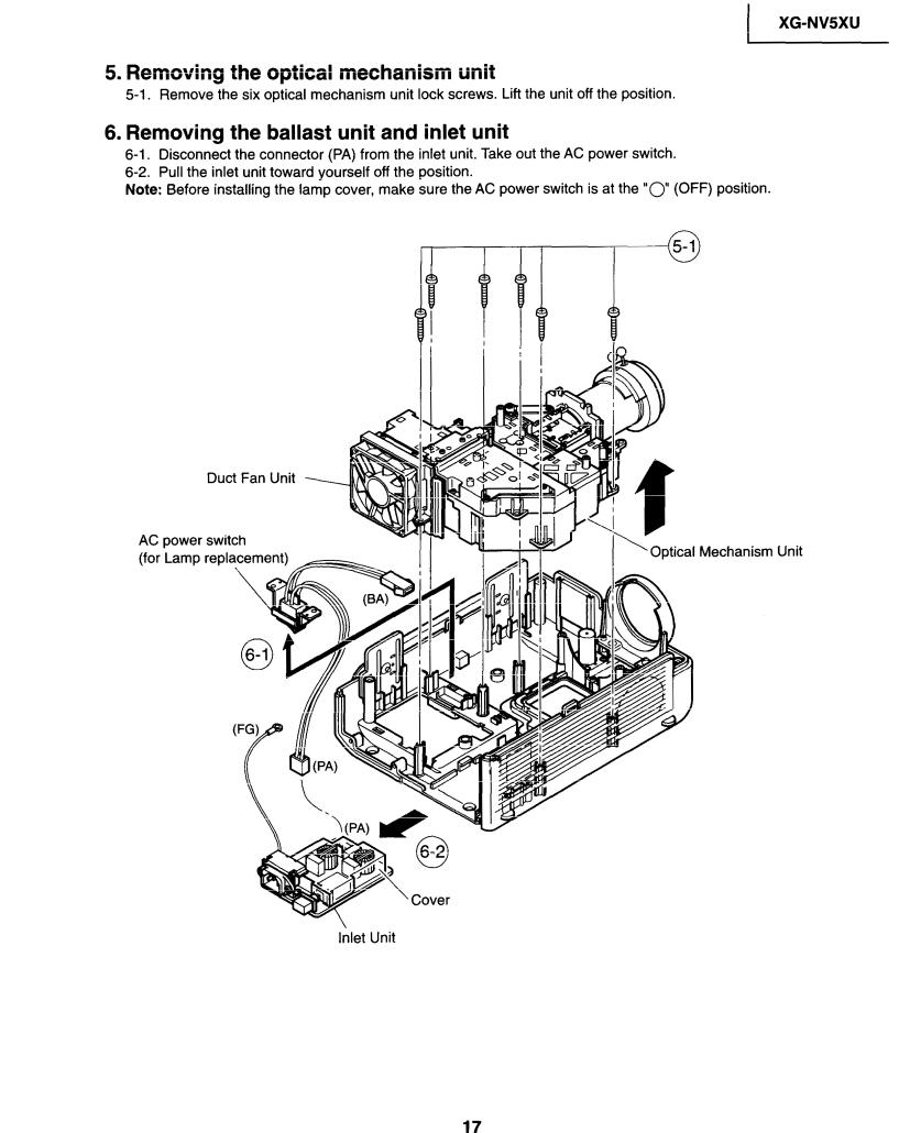
5. Removing the optical mechanism |
unit |
|
unit off the position. |
|||||||
5-1. |
Remove |
the six optical mechanism |
unit |
lock |
screws. |
Lift the |
||||
6. Removing the ballast unit and |
inlet unit |
|
power switch. |
|||||||
6-l. |
Disconnect |
the connector |
(PA) from the |
inlet |
unit. Take out the AC |
|||||
6-2. |
Pull the |
inlet |
unit toward |
yourself off the |
position. |
|
switch |
is at the “0” (OFF) position. |
||
Note: |
Before |
installing the lamp cover, |
make |
sure |
the AC |
power |
||||
XG-NV5XU
|
Duct Fan Unit |
|
|
|
AC power |
switch |
|
Mechanism Unit |
|
(for Lamp |
replacement) |
_---_ |
||
|
Inlet Unit
17


XG-NVSXU |
I |
|
|
|
|
|
|
|
|
No. |
1Adjusting point |
1 |
Adjusting conditions |
|
7
RGB 1 system black level signal amplitude (odd-numbered)
1.Make the following choice: Group : OUTPUT 1 Subject : Rl-BLK
Rl-GAIN
For green, choose the subjects Gl-BLK and Gl-
GAIN.
For blue, choose the subjects Bl -BLK and Bl -GAIN.
|
|
|
Adjusting |
procedure |
|
|||
• |
Choose |
the |
subject |
Rl-GAIN and adjust |
the sig- |
|||
|
nal amplitude |
to 3.6 kO.1 Vp-p |
using the |
control |
||||
|
switches |
or the remote |
controller |
buttons. |
|
|||
• |
Next,choose |
the subject |
R-BLK and adjust the black |
|||||
|
peak level to 3.2 1t0.lV |
DC. |
|
|
||||
|
|
|
|
3.6Vp-p |
|
|
||
|
|
|
|
|
|
(Adjust to 3.3Vp-p |
||
|
|
|
_ ____-__.1 |
for green and blue.) |
||||
2. Connect |
the oscilloscope |
to |
TPllOl |
for red. |
|
TP1201 |
for green |
|
TP1301 |
for blue |
|
•
|
4_JIY-_-._ ____-- |
. . |
|
|
||
|
|
|
f |
|
|
|
|
3.2V DC |
|
|
|
|
|
|
(Adjust to 3.4V DC for green and blue.) |
|||||
Adjust |
the |
signal’s amplitude |
and maximum |
black |
||
level |
to 3.3 |
f O.lVp-p |
and |
3.4 |
f 0.1 V DC, |
respec- |
tively, |
for green and |
blue. |
|
|
|
|
8
P
SIGNAL
1. Connect |
the oscilloscope |
to |
• |
Adjust the PSIG |
waveform |
to the |
one |
shown |
below. |
|||||
TP1102 |
for red. |
|
|
|
|
|
|
|
|
|
|
|
|
|
TP1202 |
for green |
|
|
|
|
|
|
|
|
|
|
|
|
|
TP1302 |
for blue. |
|
|
|
|
|
. |
|
|
7.8V |
DC |
----------- |
||
|
|
|
|
|
|
|
|
|
|
|
|
|||
2. Make the following |
choice: |
|
|
PSIG |
|
|
|
1 |
|
|
|
|
||
|
|
|
|
|
|
|
|
|
|
|||||
|
|
|
|
|
|
|
|
|
|
|
||||
Group |
: OUTPUT |
2 |
|
|
|
i:- |
|
1 |
|
|
|
|
|
|
Subject |
: PSIG-H |
|
|
|
|
|
|
|
|
|
|
|
||
|
|
|
|
|
|
|
|
|
|
|
|
|||
|
|
|
|
2.3V |
DC |
5.9V |
DC |
|
|
|||||
|
: PSIG-L |
|
|
|
|
|
|
|||||||
|
|
|
|
(Adjust |
with PSIG-H.) |
(Adjust with |
PSIG-L.) |
|||||||
|
|
|
|
|
||||||||||
|
|
|
|
|
|
_~GND |
|
|
|
|
|
|
|
|
|
|
|
|
• |
For the |
green |
and |
blue |
colors, |
make |
sure |
|||
|
|
|
|
|
theirwaveforms |
are |
similar |
to that |
of the red |
color. |
||||
9
Sample-and- hold pulse phase RCK-PHASE GCK-PHASE BCK-PHASE
1.
2.
Feed the XGA mode 75Hz |
||||||
black |
signal. |
|
|
|
||
Make |
the |
following |
choice: |
|||
Group |
|
: |
OUTPUT |
3 |
|
|
Subject |
: |
SH-PHASE |
|
|||
(Have |
|
the |
standard |
level at |
||
8.) |
|
|
|
GCK- |
and |
|
Fix the RCK-, |
||||||
BCK-PHASE settings |
all to |
|||||
8. |
|
|
|
|
|
|
•
Using |
the control |
switches |
or the |
remote |
controller |
|
||
buttons, |
make sure that the |
“OUTPUT |
3” charac- |
|||||
ters are |
not blurry |
and there |
is no ghost image. |
If |
||||
such |
blur or ghost |
occurs, |
finely |
adjust |
the setting |
|||
in the |
range of 7-9. |
|
|
|
|
|
||
26


 Loading...