


Dear SHARP Customer
Welcome to the SHARP Family. We are pleased that you are now the owner of a SHARP Color LCD Projector built for outstanding quality, reliability and performance.
Every SHARP Color LCD Projector is adjusted for a proper picture and has passed through the most stringent quality control tests at the factory. We have prepared this OPERATION MANUAL so that you have the ability to adjust the picture and color to your personal viewing preference.
We sincerely hope that you will be satisfied with the quality and performance of your Color LCD Projector for many years to come.
Please read the instructions carefully, and keep them handy for future reference.
IMPORTANT
For your assistance in reporting the loss or theft of your Color LCD Projector, please record the Serial Number located on the rear of the projector and retain this information.
Model No.: XG-E3000U
Serial No.:
Important Information
There are two important reasons for prompt warranty registration of your new SHARP LCD Projector, using the REGISTRATION CARD packed with the projector.
1) WARRANTY
This is to assure that you immediately receive the full benefit of the parts, service and labor warranty applicable to your purchase.
2) CONSUMER PRODUCT SAFETY ACT
To ensure that you will promptly receive any safety notification of inspection, modification, or recall that SHARP may be required to give under the 1972 Consumer Product Safety Act,
PLEASE READ CAREFULLY THE IMPORTANT “LIMITED WARRANTY” CLAUSE. U.S.A. ONLY
WARNING: High brightness light source, do not stare into the beam of light, or view directly.
Be especially careful that children do not stare directly into the beam of light.
WARNING: TO REDUCE THE RISK OF FIRE OR ELECTRIC SHOCK, DO NOT EXPOSE
THIS PRODUCT TO RAIN OR MOISTURE.
CAUTION |
RISK OF ELECTRIC SHOCK. |
DO NOT OPEN. |
CAUTION: TO REDUCE THE RISK OF ELECTRIC SHOCK, |
DO NOT REMOVE COVER. |
NO USER-SERVICEABLE PARTS INSIDE. |
REFER SERVICING TO QUALIFIED SERVICE |
PERSONNEL. |
The lightning flash with arrowhead symbol, within an equilateral triangle, is intended to alert the user to the presence of uninsulated “dangerous voltage” within the product’s enclosure that may be of sufficient magnitude to constitute a risk or electric shock to persons.
The exclamation point within a triangle is intended to alert the user to the presence of important operating and maintenance (servicing) instructions in the literature accompanying the product.
E-1
WARNING: FCC Regulations state that any unauthorized changes or modifications to this equipment not expressly approved by the manufacturer could void the user’s authority to operate this equipment.
U.S.A. ONLY
INFORMATION
This equipment has been tested and found to comply with the limits for a Class A digital device, pursuant to Part 15 of the FCC Rules. These limits are designed to provide reasonable protection against harmful interference when the equipment is operated in a commercial environment. This equipment generates, uses, and can radiate radio frequency energy and, if not installed and used in accordance with the instruction manual, may cause harmful interference to radio communications. Operation of this equipment in a residential area is likely to cause harmful interference, in which case the user will be required to correct the interference at his own expense.
U.S.A. ONLY
The enclosed RGB signal cable and Macintosh adaptor must be used with the device. The cable and adaptor are provided to ensure that the device complies with FCC Class A verification. 

Important Safeguards
Electrical energy can perform many useful functions. This unit has been engineered and manufactured to ensure your personal safety. But IMPROPER USE CAN RESULT IN POTENTIAL ELECTRICAL SHOCK OR FIRE HAZARD. In order not to defeat the safeguards incorporated into this LCD Projector, observe the following basic rules for its installation, use and servicing. For your own protection and reliable usage of your LCD Projector, please be sure to read these “Important Safeguards” carefully before use.
1)Read Instructions – All the safety and operating instructions should be read before the product is operated.
2)Retain Instructions – The safety and operating instructions should be retained for future reference.
3)Heed Warnings – All warnings on the product and in the operating instructions should be adhered to.
4)Follow Instructions – All operating and use instructions should be followed.
5)Cleaning – Unplug this product from the wall outlet before cleaning. Do not use liquid cleaners or aerosol cleaners. Use a damp cloth for cleaning.
6)Attachments – Do not use attachments not recommended by the product manufacturer as they may cause hazards.
7)Water and Moisture – Do not use this product near water – for example, near a bathtub, wash bowl, kitchen sink, or laundry tub; in a wet basement; or near a swimming pool; and the like.
8)Accessories – Do not place this product on an unstable cart, stand, tripod, bracket, or table. The product may fall, causing serious injury to a child or adult, and serious damage to the product. Use only with a cart, stand, tripod, bracket, or table recommended by the manufacturer, or sold with the product. Any mounting of the product should follow the manufacturer’s instructions, and should use a mounting accessory recommended by the manufacturer.
9)A product and cart combination should be moved with care. Quick stops, excessive force, and uneven surfaces may cause the product and cart combination to overturn.
10)Ventilation – Slots and openings in the cabinet are provided for ventilation to ensure reliable operation of the product and to protect it from overheating, and these openings must not be blocked or covered. The openings should never be blocked by placing the product on a bed, sofa, rug, or other similar surface. This product should not be placed in a built-in installation such as a bookcase or rack unless proper ventilation is provided or the manufacturer’s instructions have been adhered to.
11)Power Sources – This product should be operated only from the type of power source indicated on the marking label. If you are not sure of the type of power supply to your home, consult your product dealer or local power company. For products intended to operate from battery power, or other sources, refer to the operating instructions.
12)Grounding or Polarization – This product is equipped with a three-wire grounding-type plug, a plug having a third (grounding) pin. This plug will only fit into a grounding-type power outlet. This is a safety feature. If you are unable to insert the plug into the outlet, contact your electrician to replace your obsolete outlet. Do not defeat the safety purpose of the grounding-type plug.
13)Power-Cord Protection – Power-supply cords should be routed so that they are not likely to be walked on or pinched by items placed upon or against them, paying particular attention to cords at plugs, convenience receptacles, and the point where they exit from the product.
E-2

14)Lightning – For added protection for this product during a lightning storm, or when it is left unattended and unused for long periods of time, unplug it from the wall outlet and disconnect the cable system. This will prevent damage to the product due to lightning and power-line surges.
15)Overloading – Do not overload wall outlets, extension cords, or integral convenience receptacles as this can result in a risk of fire or electric shock.
16)Object and Liquid Entry – Never push objects of any kind into this product through openings as they may touch dangerous voltage points or short-out parts that could result in a fire or electric shock. Never spill liquid of any kind on the product.
17)Servicing – Do not attempt to service this product yourself as opening or removing covers may expose you to dangerous voltage or other hazards. Refer all servicing to qualified service personnel.
18)Damage Requiring Service – Unplug this product from the wall outlet and refer servicing to qualified service personnel under the following conditions:
a)When the power-supply cord or plug is damaged.
b)If liquid has been spilled, or objects have fallen into the product.
c)If the product has been exposed to rain or water.
d)If the product does not operate normally by following the operating instructions. Adjust only those controls that are covered by the operating instructions, as an improper adjustment of other controls may result in damage and will often require extensive work by a qualified technician to restore the product to normal operation.
e)If the product has been dropped or damaged in any way.
f)When the product exhibits a distinct change in performance - this indicates a need for service.
19)Replacement Parts – When replacement parts are required, be sure the service technician has used replacement parts specified by the manufacturer or with the same characteristics as the original part. Unauthorized substitutions may result in fire, electric shock, or other hazards.
20)Safety Check – Upon completion of any service or repairs to this product, ask the service technician to perform safety checks to determine that the product is in proper operating condition.
21)Wall or Ceiling Mounting – The product should be mounted to a wall or ceiling only as recommended by the manufacturer.
22)Heat – The product should be situated away from heat sources such as radiators, heat registers, stoves, or other products (including amplifiers) that produce heat.
Cautions Concerning the Laser Pointer
|
|
|
"COMPLIES WITH 21 CFR SUBCHAPTER J" |
|||
|
CAUTION |
|
||||
|
|
SHARP PLAZA, MAHWAH, NEW JERSEY 07430 |
||||
|
|
|
SHARP ELECTRONICS CORPORATION |
|||
|
|
|
TEL : 1-800-BE-SHARP |
|
|
|
|
LASER RADIATION- |
|
|
U.S.A. ONLY |
|
|
|
|
|
|
|||
|
DO NOT STARE INTO BEAM |
|
REMOTE CONTROL |
|
|
|
|
|
|
|
|
||
|
WAVE LENGTH : 670nm |
|
MODEL NO. : RRMCG1392CESA |
|
|
|
|
|
DC6V (1.5VX4PCS.) |
|
|
|
|
|
MAX. OUTPUT : 1mW |
|
MADE IN JAPAN |
|
|
|
|
CLASS II LASER PRODUCT |
|
FABRIQUÉ AU JAPON |
|
|
|
|
|
|
|
|
|
|
AVOID EXPOSURE-LASER
RADIATION IS EMITTED
FROM THIS APERTURE.
LASER LIGHT WINDOW
The laser pointer on the remote control emits a laser beam from the laser light window shown in the figure to the left. The laser emitted is a class II laser; therefore, do not look into the laser window or shine the laser beam on yourself or other people. The three marks to the left are the caution labels for the laser beam.
Always use the laser pointer at temperatures between 41°F and 104°F (+5°C and +40°C).
Caution: Use of controls or adjustments or performance of procedures other than those specified herein may result in hazardous radiation exposure.
E-3

Notes on Operation
About the Temperature Monitor Function: |
|
• If the projector starts to overheat due to set-up problems or a dirty air filter, “TEMP.” will flash in |
|
TEMP. |
|
the upper-left corner of the picture. If the temperature continues to rise, then the lamp will turn |
|
off, the TEMPERATURE WARNING indicator will flash, and after a 90-second cooling-off |
|
period the power will shut off. Refer to page 32, “Maintenance Indicators,” when the “TEMP.” |
|
warning appears in the picture. |
|
About the Lamp Monitor Function: |
|
• When the projector is turned on after the lamp has been in use for more than 1,400 hours, the |
|
|
|
yellow “LAMP” display will flash on the screen for 60 seconds, as shown on the right. This is to |
LAMP |
alert you that it is time to replace the lamp. At this point, take your projector to the nearest |
|
Authorized Sharp Industrial LCD Products Dealer or Service Center to have the lamp re- |
|
placed. |
|
•If the lamp is used for more than 1,500 hours, the projector power will automatically turn off, and the projector will be in STANDBY mode.
•Refer to page 32, “Maintenance Indicators,” when the “LAMP” display warning appears.
Caution: If “LAMP” begins to flash on the screen, be sure to take your projector to the nearest Authorized Sharp Industrial LCD Products Dealer or Service Center to have the lamp replaced.
Outstanding Features
Allows easy projection of large screen, full-color computer and video images.
∙ Can be projected directly onto a video screen or white wall.
∙ Lightweight, convergence-free system for easy installation.
DIRECT COMPUTER COMPATIBILITY
A multi-scan RGB Input accepts signals from SXGA (1,280 dots × 1,024 lines compressed), XGA (1,024 dots × 768 lines), SVGA (800 dots × 600 lines), VGA and Mac (1,024 dots × 768 lines maximum) compatible computers without the need for any additional hardware.
FLEXIBLE USE
In addition to the standard front projection mode, the menu driven functions can be used to instantly reverse the image for rear projection, and invert the image for ceiling mounting.
POWER ZOOM AND FOCUS
∙ Provides simple screen-size adjustments from either the projector or the remote control.
∙ Screen projection size adjusts from 40 to 500 inches.
LENS SHIFT
The lens can be easily raised and lowered to minimize or eliminate “Keystone” type effects.
HIGH PICTURE QUALITY
The three LCD panels contain 786,432 × RGB pixels to achieve exceptionally bright, high quality video images with up to 520 scan doubled TV lines of resolution (700 lines for S-video).
VERSATILE REMOTE CONTROL
∙ Built-in wireless mouse allows simultaneous operation of projector and computer.
∙ Built-in Laser Pointer for professional presentations.
BUILT-IN STEREO SPEAKERS
Built in 3 W + 3 W stereo amplifiers and speakers eliminate the need for external audio components.
USE WITH “PLUG AND PLAY”
“Plug and play” compatible with VESA DDC 1 and DDC 2B standards.
E-4

Location of Controls
FRONT VIEW
Speakers
Cooling fan (Exhaust vent)
Carrying handle
ON/OFF
POWER
LAMP
TEMP.
POWER ON/OFF button
Remote sensor
POWER indicator
LAMP REPLACEMENT indicator
TEMPERATURE WARNING indicator
Lamp cage cover (Natural ventilation)
Cooling fan (Intake vent)
Cautions:
∙The exhaust vent, the lamp cage cover and adjacent areas may be extremely hot during projector operation. To prevent injury, do not touch these areas until they have sufficiently cooled.
∙Allow at least 4" (10 cm) of space between the cooling fan (exhaust vent) and the other nearest wall or obstruction.
∙If the cooling fan becomes obstructed, a protection device will automatically turn off the projector lamp. This does not indicate a malfunction. Remove the projector plug from the wall outlet and wait 10 minutes. Then turn on the power by plugging the cord back in. This will return the projector to its normal mode.
OPERATION PANEL ON SIDE OF PROJECTOR
|
|
|
|
BLACK |
|
INPUT |
MENU |
ENTER |
|
LENS |
SCREEN MUTE |
VOLUME |
SELECT |
MN |
EN |
ADJ. |
LN |
B |
|
IN |
|
|
|
|
|
|
|
|
|
|
|
|
|
|
|
|
|
|
|
|
|
|
|
|
|
|
|
|
|
|
|
|
|
|
|
BLACK |
|
|
|
|
|
|
MENU |
|
|
ADJUSTMENT |
|
VOLUME UP- |
|
|
||||||
|
|
|
SCREEN |
|
|
|
|||||||
button |
|
( |
/ , / ) buttons |
|
button |
|
DOWN buttons |
|
|
||||
|
|
|
|
||||||||||
|
ENTER button |
|
LENS button MUTE button |
INPUT SELECT |
|||||||||
|
|
|
|
|
|
|
|
|
|
|
button |
||
SIDE AND REAR VIEW
|
Cooling fan |
|
|
|
|
MOUSE TERMINAL |
|
|||
COMPOSITE |
(Intake vent) |
RS-232C (D-sub 9-pin) |
Use when operating your personal computer with the |
|||||||
|
wireless mouse remote control. |
|||||||||
VIDEO INPUT 1 |
Use when controlling the projector |
Left Terminal: D-sub 9-pin (for IBM/Mac) |
||||||||
Video: BNC |
|
from your personal computer. |
Right Terminal: 9-pin mini DIN (for NEC in JAPAN) |
|||||||
Audio: RCA |
|
|
|
|
|
|
|
|
|
WIRED REMOTE |
S-VIDEO INPUT |
|
S-VIDEO |
|
|
|
|
|
|
REMOTE |
|
(4-pin mini DIN) |
|
AUDIO |
|
PC CONTROL |
|
MOUSE |
FOR PC98 |
CONTROL INPUT |
||
|
|
VIDEO |
|
|
WIRED |
|
||||
COMPOSITE |
|
L |
R |
|
|
|
|
|
|
(3.5 mm Mono Minijack) |
|
IN |
|
|
|
|
|
|
|
||
|
1 |
|
|
|
|
|
|
|
|
|
VIDEO INPUT 2 |
|
L |
R |
INPUT1 |
COMPUTER |
RGB |
L |
R |
AUDIO IN |
COMPUTER AUDIO INPUT |
|
|
|
|
OUTPUT |
AUDIO OUTPUT |
COMPUTER |
|
|||
Video: BNC |
A.C. 120V |
2 |
|
|
|
|
|
|
|
(3.5 mm Stereo Minijack) |
C.A. 120V |
|
|
|
|
|
|
|
|||
|
|
IN |
|
|
|
|
|
|
|
|
Audio: RCA |
ON |
|
|
FILTER R |
|
INPUT2 |
|
|
DC5V OUTPUT |
AUDIO OUTPUT: RCA |
MAIN POWER |
|
OUT |
|
G |
B |
H |
V |
MAX CURRENT 1A |
|
|
|
|
ON |
|
|
|
|
|
DC 5V 1A OUTPUT |
||
switch |
|
|
|
|
|
|
|
|
||
OFF |
|
|
OFF |
|
|
|
|
|
||
|
AC INLET |
COMPUTER RGB |
Filter ON/OFF |
COMPUTER RGB INPUT 2: BNC |
||||||
|
INPUT 1 connector (HD-15) |
switch |
|
(R, G, B, H(C)-SYNC, V-SYNC) |
||||||
COMPOSITE VIDEO OUTPUT: BNC |
COMPUTER RGB OUTPUT connector (HD-15) |
|
||||||||
Notes:
•The DC 5V OUTPUT jack cannot supply a current of more than 1A.
•When connecting a Macintosh Series computer that outputs C-SYNC, connect the cable to the COMPUTER RGB 2 INPUT H-SYNC input terminal.
E-5

Operating the Wireless Mouse Remote Control
The functions of your personal computer’s mouse have been built into the remote control enabling you to operate your projector and personal computer with only the remote control.
1.Slide the MAIN POWER switch on the side of the unit on.
2.Press the POWER ON button on the front panel of the remote control to turn the projector power on.
3.When using the remote control as a wireless mouse, move the MOUSE/ADJUSTMENT sliding switch to the MOUSE position. When using the remote control to operate the projector, move the MOUSE/ADJUSTMENT sliding switch to the ADJ. position. To activate the remote control key back-light feature, press the LIGHT button on the remote control. The colors of the buttons will change as shown in the table at the bottom of this page.
Wireless Mouse Remote Control
FRONT VIEW |
TRANSMIT indicator |
||
|
|||
MUTE button |
|
|
|
|
ON |
|
VOL |
POWER ON/OFF |
|
|
MUTE |
OFF |
|
|
|
buttons |
|
|
|
|
BLACK SCREEN/ |
LASER/ |
|
BLACK SCREEN/ |
LENS |
B |
MENU |
|
|
||
LN |
|
MN |
|
LENS button |
|
||
|
|
|
|
RIGHT-CLICK/ENTER
button |
R-CLICK/ENTER |
|
|
INPUT SELECT |
|
|
DATA1 |
DATA2 |
INPUT SELECT |
|
|
buttons |
VIDEO1 |
VIDEO2 |
|
|
|
INPUT CHECK button |
CHECK |
|
MOUSE label |
MOUSE |
ADJ. |
MOUSE/ADJUSTMENT |
LIGHT |
|
switch |
||
|
||
LIGHT button |
|
|
Using the remote control |
LCD PROJECTOR |
|
|
||
in a dark room |
|
∙Press the LIGHT button to turn on the back-lights for the operation buttons for about 5 seconds. The back-light colors are explained in the table to the right.
Note:
•If the MAIN POWER switch on the remote control is left on for more than 10 minutes without operation, the power will automatically turn off. To turn the power back on, press any button on the remote control for at least one second.
SIDE VIEW
ON
R/C
OFF
VOLUME UP-DOWN buttons
LASER POINTER/MENU button
MOUSE/ADJUSTMENT ( /
/ ),(
),( /
/ ) buttons
MAIN POWER switch of remote control
Note:
When transporting the remote control, turn off the MAIN POWER switch to avoid draining the batteries.
LEFT-CLICK button
Remote control handling precautions
• The laser beam used in this product is harmless when directed onto the skin, however please be careful not to project the beam directly into the eyes. Do not stare into the beam using an optical instrument.
• Do not expose the remote control to shocks, liquids or high humidity.
The remote control may not operate normally if exposed to direct sunlight or other intense light sources. Should
this happen, reposition the light source or the LCD ADJ. label Projector.
When you change the setting of the MOUSE/ADJUSTMENT switch, the functions of certain buttons on the remote control change. You can tell which function the button currently possesses by the color of its backlight display.
Button name |
Position of MOUSE/ADJUSTMENT switch |
||
|
|
|
|
|
MOUSE |
|
ADJ. |
LASER POINTER/MENU |
LASER POINTER (GREEN) |
|
MENU (RED) |
|
|
|
|
RIGHT-CLICK/ENTER |
RIGHT-CLICK (GREEN) |
|
ENTER (RED) |
|
|
|
|
MOUSE/ADJUSTMENT |
MOUSE (NOT LIT) |
ADJ. |
/ , / (NOT LIT) |
|
|
|
|
LEFT-CLICK |
ON (NOT LIT) |
|
––– |
|
|
|
|
BLACK SCREEN/LENS |
BLACK SCREEN (GREEN) |
|
LENS (RED) |
|
|
|
|
POWER ON/OFF |
|
|
|
|
|
|
|
VOLUME UP-DOWN |
|
|
|
|
|
|
|
MUTE |
|
|
|
|
|
|
|
VIDEO 1 |
|
|
|
|
|
|
|
VIDEO 2 |
ON (RED) |
|
|
|
|
|
|
DATA 1 |
|
|
|
|
|
|
|
DATA 2 |
|
|
|
|
|
|
|
INPUT CHECK |
|
|
|
|
|
|
|
E-6

TOP VIEW
REMOTE CONTROL
SIGNAL TRANSMITTER
WIRED REMOTE CONTROL INPUT  (3.5 mm Mono Minijack)
|
|
|
LASER LIGHT WINDOW |
||||
|
|
|
Laser light shines out of |
||||
|
|
|
this window. |
||||
|
|
|
|
|
|
|
|
|
CAUTION |
|
"COMPLIES WITH 21 CFR SUBCHAPTER J" |
|
|||
|
|
SHARP PLAZA, MAHWAH, NEW JERSEY 07430 |
|
||||
|
|
|
SHARP ELECTRONICS CORPORATION |
|
|||
|
|
|
TEL : 1-800-BE-SHARP |
|
|
|
|
|
LASER RADIATION- |
|
|
U.S.A. ONLY |
|
|
|
|
|
|
|
|
|||
|
DO NOT STARE INTO BEAM |
|
REMOTE CONTROL |
|
|
|
|
|
|
|
|
|
|
||
|
WAVE LENGTH : 670nm |
|
MODEL NO. : RRMCG1392CESA |
|
|
|
|
|
|
DC6V (1.5VX4PCS.) |
|
|
|
|
|
|
MAX. OUTPUT : 1mW |
|
MADE IN JAPAN |
|
|
|
|
|
CLASS II LASER PRODUCT |
|
FABRIQUÉ AU JAPON |
|
|
|
|
|
|
|
|
|
|
|
|
Using the optional cable with the remote control
∙When the remote control cannot be used due to the range or positioning of the projector (rear projection, etc.), connect the optional cable from the Wired Remote Control Input jack on the remote control to the Wired Remote Input on the side of the projector.
Note:
∙The signal transmitter does not function when the optional cable is connected to the remote control.
The laser pointer on the remote control emits a laser beam from the laser light window shown in the figure to the left. The laser emitted is a class II laser; therefore, do not look into the laser window or shine the laser beam on yourself or other people. The two marks to the left are the caution labels for the laser beam.
Always use the laser pointer at temperatures between 41°F and 104°F (+5°C and +40°C).
REAR VIEW
Press in and |
|
downward on |
|
the arrow |
|
mark and |
Insert the side |
remove. |
tabs into their |
|
slots and press |
|
in the cover |
|
until properly |
|
seated. |
Transmission range |
Reception range |
30° |
30° |
Max. distance: 23' (7 m)
30° |
45° |
|
Inserting the Batteries
Remove the battery cover as shown and insert four AA size batteries making sure their polarities match the (+) and (–) marks inside the battery compartment.
Notes:
Incorrect use of batteries may cause them to leak or burst.
∙Insert the batteries with the (+) and (–) polarities as indicated.
∙Remove the batteries if the remote control will not be operated for an extended period of time.
∙Maintain the batteries in a clean condition.
∙Do not mix different brands of batteries. The life expectancy of the new batteries will be shortened and the old batteries may leak.
∙When the batteries have been used up, remove them immediately to prevent leakage and damage. Leaked battery fluid may irritate the skin. Remove any battery fluid by wiping with a cloth.
∙Due to storage conditions and the shelf life of the supplied batteries, they may run out after a short time. If so, replace them with new batteries as soon as possible.
Remote control positioning
Use the remote control as shown in the figures on the left.
Note:
∙The signal from the remote control can be reflected off the screen for easy operation. However, the effective distance of the signal may differ due to the screen material.
E-7

Wireless Mouse Functions
mThe wireless mouse functions and laser pointer on the remote control can help you create a more professional presentation.
•By attaching the provided mouse cable to both the mouse terminal on your projector and the mouse terminal on your personal computer, you can use the wireless mouse built into the remote control, instead of the mouse equipped with your personal computer, to operate your personal computer. The wireless mouse functions will work with personal computers compatible with IBM PS/2, serial (RS232C) or Apple ADB type mouse systems.
Projector
Connection Example
Personal computer
To mouse terminal
|
|
|
|
BLACK |
|
INPUT |
MENU |
ENTER |
|
LENS |
SCREEN MUTE |
VOLUME |
SELECT |
MN |
EN |
ADJ. |
LN |
B |
|
IN |
|
VIDEO |
AUDIO |
PC CONTROL |
|
MOUSE |
FOR PC98 |
WIRED |
|
S-VIDEO |
|
|
|
|
|
REMOTE |
|
L |
R |
|
|
|
|
|
|
IN |
|
|
|
|
|
|
|
1 |
|
|
|
|
|
|
|
|
INPUT1 |
COMPUTER |
RGB |
OUTPUT |
AUDIO OUTPUT |
COMPUTER |
|
L |
R |
|
|
L |
R |
AUDIO IN |
A.C. 120V |
IN |
|
|
|
|
|
|
C.A. 120V |
2 |
|
|
|
|
|
|
ON |
|
|
|
|
INPUT2 |
|
DC5V OUTPUT |
|
|
FILTER R |
G |
B |
H |
V |
MAX CURRENT 1A |
|
OUT |
ON |
|
|
|
|
|
OFF |
|
|
|
|
|
|
|
|
|
OFF |
|
|
|
|
|
Supplied mouse cable (for IBM PS/2, serial and Apple ADB type mouse)
Functions and Operations
ON |
VOL |
|
MUTE |
POWER ON/OFF |
OFF |
|
LASER POINTER button |
|
buttons |
LENS |
LN |
MENU |
|
|
MN |
|
||
|
BLACK SCREEN/ |
LASER/ |
|
|
|
|
B |
|
|
|
|
|
|
MOUSE buttons |
|
|
R-CLICK/ENTER |
RIGHT-CLICK button |
|
|
|
INPUT SELECT |
|
|
|
|
DATA1 |
DATA2 |
|
MOUSE/ADJUSTMENT |
|
VIDEO1 |
VIDEO2 |
|
|
CHECK |
|
|
|
sliding switch |
|
MOUSE |
ADJ. |
|
|
LIGHT |
|
||
ON R/C OFF
MAIN POWER switch of remote control
LEFT-CLICK button
LCD PROJECTOR
∙First, connect the units as shown above, and turn the projector power on.
∙Second, turn the computer power on.
∙Next, slide the MAIN POWER switch on the side of the remote control.
∙When using the remote control as a wireless mouse, move the MOUSE/ADJUSTMENT sliding switch to the MOUSE position.
Notes:
•In some situations the wireless mouse may be inoperable if your computer port is not correctly set-up. Please refer to your computer owners manual for details on setting-up/installing the correct Mouse Driver.
•Do not connect or remove the mouse control cable to/from your computer while it is on. This may damage your computer.
•Do not connect the mouse input terminal for IBM/Mac and the mouse input terminal for PC98 simultaneously.
MOUSE buttons
By lightly pressing the up/down and right/left arrow buttons located on the front of the remote control, you can move the mouse cursor on your monitor screen.
Note: The amount of pressure applied to the MOUSE button determines the speed the
mouse cursor travels. Pressing lightly on the periphery of the MOUSE button Mouse cursor makes the mouse cursor move slowly. Pressing hard makes it move quickly.
LEFT-CLICK button The LEFT-CLICK button on the back of the remote control corresponds to the left button of the mouse on two-button mouse systems.
RIGHT-CLICK button The RIGHT-CLICK button on the front of the remote control corresponds to the right button on two-button mouse systems.
Note: For one-button mouse systems use either the LEFT-CLICK or RIGHT-CLICK button.
LASER POINTER button Press the LASER POINTER button to activate the laser pointer.
When the button is pressed, the light stays on; when the button is released, the light goes off. However, even when the button is pressed continuously, the light automatically goes off 1 minute after it goes on. To turn it on again press the laser pointer button one more time.
CAUTION
LASER RADIATION-
DO NOT STARE INTO BEAM
WAVE LENGTH : 670nm MAX. OUTPUT : 1mW
CLASS II LASER PRODUCT
"COMPLIES WITH 21 CFR SUBCHAPTER J"
SHARP ELECTRONICS CORPORATION SHARP PLAZA, MAHWAH, NEW JERSEY 07430
TEL : 1-800-BE-SHARP |
U.S.A. ONLY |
REMOTE CONTROL
MODEL NO. : RRMCG1392CESA
DC6V (1.5VX4PCS.)
MADE IN JAPAN
FABRIQUÉ AU JAPON
The laser pointer on the remote control emits a laser beam from the laser light window. The laser emitted is a class II laser; therefore, do not look into the laser window or shine the laser beam on yourself or other people. The two marks to the left are the caution labels for the laser beam.
Always use the laser pointer at temperatures between 41°F and 104°F (+5°C and +40°C).
E-8
Setting Up the Projector
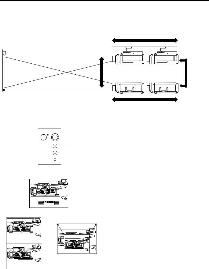
Using the Focus, Zoom and Lens Shift
∙Lens Shift, Zoom, Focus and Reversed/Inverted Image mode functions broaden your options for projector placement.
∙See pages 10, 12 and 13 for details on projector setup.
SIDE VIEW
Zoom
Ceiling setting
2 |
ON/OFF |
|
POWER |
|
LAMP |
|
TEMP. |
Lens Shift
POWER indicator
Invert Image
Table setting
Zoom
1. Turn on the MAIN POWER.
Turn on the MAIN POWER switch on the side of the projector.
2. Turn on the POWER.
Press the POWER ON/OFF button on the projector or the POWER ON button on the remote control to turn on the power.
3 |
|
|
FOCUS |
|
|
|
|
|
|
|
|
← |
F O C U S |
|
|
SHIFT |
← |
|
|
|
|
|
||
|
|
|
ZOOM |
|
|
|
|
|
|
↔ |
S H I F T |
|
← |
|
|
|
|
|
|
|
|
|
|
Z O O M |
|
S H I F T |
|
|
|
E-9
3. Press the LENS button.
∙When using the remote control to adjust the picture, move the MOUSE/ADJUSTMENT sliding switch to the ADJUSTMENT position. When the LENS button on the remote control or on the projector is pressed, the LENS adjustment mode is indicated for about 8 seconds.
∙If the LENS button is pressed while the mode is indicated on the screen, the picture adjustment mode changes as shown on the left.
∙You can adjust the picture as shown on the left by pressing the ADJUSTMENT (  ) or (
  ) buttons for FOCUS and ZOOM or the ADJUSTMENT (
 ) or (
 ) buttons for SHIFT while in ADJUST mode.
Note:
•Do not attempt to adjust the lens by hand as it may damage the lens mechanism.
∙Adjust the focus until the picture on the screen is sharp.
∙The focus pattern appears on the screen.
∙The picture can be adjusted to the desired size within the zoom lens range.
∙The picture can be adjusted within the shift range of the lens.
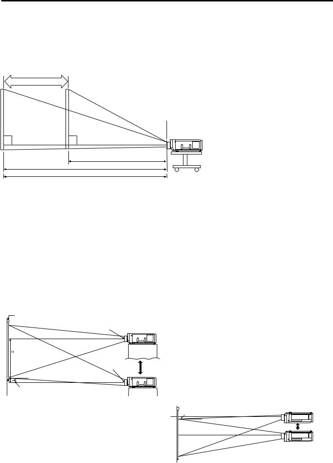
Projector Distance and Picture Size Relationship
mThe motorized zoom lens allows adjustment to the image size within the projector’s range.
mThe picture can be focused from a minimum of approximately 4.5 ft (1.4 m) to a maximum of 96.3 ft (29.4 m) from the screen. Please set up the projector within this range.
Distance from screen
Picture size: 100 inches (254 cm)
Zoom adjustment range: 19.0 ft–11.8 ft
Picture size |
Projection distance (L) |
||
|
|
|
|
(diag.) |
Maximum projection distance |
Minimum projection distance |
|
500 inches |
96.3 ft (29.4 m) |
60.5 ft (18.4 m) |
|
400 inches |
77.0 ft (23.5 m) |
48.3 ft (14.7 m) |
|
|
|
|
|
300 inches |
57.7 ft (17.6 m) |
36.1 ft (11.0 m) |
|
200 inches |
38.3 ft (11.7 m) |
23.9 ft (7.3 m) |
|
150 inches |
28.6 ft (8.7 m) |
17.9 ft (5.5 m) |
|
|
|
|
|
100 inches |
19.0 ft (5.8 m) |
11.8 ft (3.6 m) |
|
|
|
|
|
80 inches |
15.1 ft (4.6 m) |
9.3 ft (2.9 m) |
|
60 inches |
11.2 ft (3.4 m) |
6.9 ft (2.1 m) |
|
40 inches |
7.3 ft (2.2 m) |
4.5 ft (1.4 m) |
|
|
|
|
|
90° |
90° |
Minimum L: 11.8 ft (3.6 m) Maximum L: 19.0 ft (5.8 m)
The formula for picture size and projection distance y1 = 0.0592 – 0.1175
y2 = 0.03712 – 0.1211
x : Picture size (diag.) (inches)
y1 : Maximum projection distance (m) y2 : Minimum projection distance (m)
Note: There is an error of 54 inches (510 cm) in the formula above.
Distance between lens and screen: L
Diagram shows the lens shift position set at the factory.
•Above is an illustration of maximum and minimum projection distances for the XG-E3000U with a picture size of 100 inches (254 cm). Move the projector forward or back if the edges of the image are distorted.
Height of Projector
m This projector is equipped with a lens shift function that lets you adjust the projection height without moving the
projector. |
|
|
|
m Adjust to match the setup configuration. |
Picture size |
Distance from lens center to lower edge of screen (H) |
|
|
(diag.) |
Lower lens shift position |
Upper lens shift position |
|
500 inches |
125.4 in. (164.6 cm) |
242.2 in. (615.1 cm) |
|
400 inches |
120.4 in. (151.7 cm) |
193.7 in. (492.1 cm) |
|
|
|
|
|
300 inches |
115.3 in. (138.8 cm) |
145.4 in. (369.2 cm) |
|
200 inches |
110.2 in. (125.8 cm) |
96.9 in. (246.1 cm) |
|
150 inches |
17.6 in. (119.4 cm) |
72.7 in. (184.6 cm) |
|
|
|
|
|
100 inches |
15.1 in. (112.9 cm) |
48.5 in. (123.1 cm) |
|
80 inches |
14.1 in. (110.3 cm) |
38.8 in. (98.5 cm) |
Picture size: 100 inches (254 cm) |
60 inches |
13.1 in. (17.8 cm) |
29.1 in. (73.9 cm) |
Screen |
40 inches |
12.0 in. (15.2 cm) |
19.4 in. (49.3 cm) |
|
|
|
|
Lens center |
|
|
|
Upper lens shift portion
H: 48.5 inches
(123.1 cm)
Lens center
Lower edge of screen (white portion) = Standard (0) point
Lower lens shift portion H: 15.1 inches (112.9 cm)
• Ceiling Mount
When the projector is in the inverted position, use the upper edge of the screen as the base line, and exchange the lower and upper lens shift values.
Note:
Upper lens shift position (High mount setup)
Lower lens shift position (Desktop setup)
–H
High edge of screen
 90˚
90˚
•Optimal image quality is produced with the projector positioned perpendicular to the screen with all feet flat and level. Tilting or angling the projector will reduce the effectiveness of the lens shift function.
E-10
Using the Image Invert/Reverse Function
■ This projector is equipped with an image invert/reverse function. The projected image can be inverted or reversed by using the MENU button and the ADJUSTMENT  and / buttons.
1
I M A G E |
A D J . |
|
|
[ O F F ] |
|
B L K S C R N D I S P |
||
|
[ O F F ] |
|
I N P U T D I S P L A Y |
||
|
[ O F F ] |
|
R E V E R S E |
||
|
|
[ O F F ] |
I N V E R T |
|
|
: S E L . |
|
|
: A D J . |
MENU : E N D |
|
1. Press the MENU button.
With the MENU screen displayed, press the ADJUSTMENT buttons to select “IMAGE ADJ”. Then press the ENTER button to display the IMAGE ADJ. screen.
∙The last MENU screen selected is indicated for about 30 seconds.
2 |
|
|
|
|
|
|
|
|
|
|
|
|
|
ADJ. |
IMAGE |
|
|
|
|
|
|
|
|
|
|
|
|
|
|
[OFF] |
|
DISP |
BLKSCRN |
|
|
|
|
|
|
|
|
|
|
|
|
|
|
[OFF] |
|
DISPLAY |
INPUT |
|
|
|
|
|
|
|
|
|
|
|
|
|
|
[ON] |
|
|
REVERSE |
|
|
|
|
|
[OFF] |
|
|
|
|
|
|
|
|
|
|
|
INVERT |
|
|
|
|
|
|
|
|
|
:SEL. |
|
|
|
|
|
|
MENU:END |
|
:ADJ. |
|
3 |
|
|
|
|
|
|
|
|
|
|
|
|
|
|
|
|
|
|
|
|
|
MENU:END |
|
:ADJ. |
|
|
|
|
|
|
|
|
|
||
|
|
|
|
|
|
|
:SEL. |
|
|
|
|
[ON] |
|
|
|
|
|
|
|
|
|
|
INVERT |
|
||
|
|
|
|
|
|
|
|
|
|
|
|
[OFF] |
|
REVERSE |
|
||
|
|
|
[OFF] |
|
|
|
|
|
|
|
|
DISPLAY |
INPUT |
|
|||
|
|
|
[OFF] |
|
|
|
|
|
|
|
|
DISP |
BLKSCRN |
|
|||
|
|
|
|
|
|
|
|
|
|
|
|
|
|
ADJ. |
IMAGE |
|
|
4 |
|
|
|
|
|
|
|
|
|
|
|
|
|
|
|
|
|
|
|
: A D J . |
MENU : E N D |
|
|
|||
|
|
|
|
|
||||
|
|
|
: S E L . |
|
|
|
|
|
|
|
|
|
|
|
[ O N ] |
|
|
|
|
|
I N V E R T |
|
|
|
||
|
|
|
|
|
[ O N ] |
|
||
|
|
|
R E V E R S E |
|
|
|||
|
|
|
|
|
|
|
[ O F F ] |
|
|
|
|
I N P U T D I S P L A Y |
|
|
|||
|
|
|
|
|
|
|
[ O F F ] |
|
|
|
|
B L K S C R N D I S P |
|
|
|||
|
|
|
|
|
|
|
|
|
|
|
|
I M A G E |
A D J . |
|
|
|
|
|
|
|
|
|
|
|
|
|
2. Reversed Image Mode
In the IMAGE ADJ. menu, press the ADJUSTMENT  /
/ buttons to select “REVERSE”. Then press the ADJUSTMENT
  /
/  buttons to select ON. The reversed image will appear.
3. Inverted Image Mode
In the IMAGE ADJ. menu, press the ADJUSTMENT  /
/ buttons to select “INVERT”. Then press the ADJUSTMENT
  /
/ buttons to select ON. The inverted image will appear.
4. Reversed Inverted Image Mode
In the IMAGE ADJ. menu, set the REVERSE and INVERT functions to ON. The reversed inverted image will appear.
5.Press the MENU button anytime to exit IMAGE ADJ.
E-11
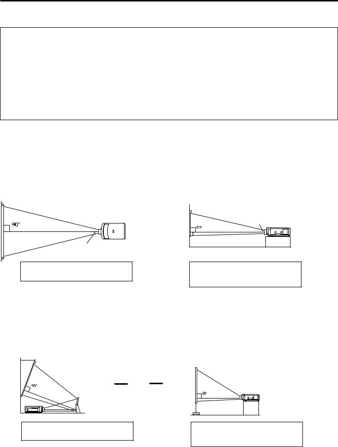
How to set up the projector and screen
Cautions: When setting up the projector
∙For minimal servicing and to maintain high image quality, SHARP recommends that this projector be installed in an area free from humidity, dust and cigarette smoke. When the projector is subjected to these environments, the lens and filter must be cleaned more often. Periodically the filter should be replaced and the projector should be cleaned internally. As long as the projector is properly maintained in this manner, use in these environments will not reduce the overall operation life. Please note that all internal cleaning must be performed by an Authorized Sharp Industrial LCD Products Dealer or Service Center.
∙Do not expose to extreme heat or cold.
Operating temperature: 41°F to 104°F (+5°C to +40°C) Storage temperature: 14°F to 140°F (120°C to +60°C)
∙Do not tilt the projector more than 5°.
■Position the screen so that it is not in direct sunlight or room light. Light falling directly onto the screen washes out colors, making viewing difficult. Close the curtains and dim the lights when using the screen in a bright or sunny room.
■The best picture will be obtained when the projector is at a 90 degree angle to the screen. Position the projector and screen as shown.
Example of a standard setup
TOP VIEW
Lens center
SIDE VIEW
Lens center |
The projector lens should be centered in the middle of the screen.
If the projector and screen are not centered properly, the picture will be distorted, making viewing difficult.
■Using the horizontal reverse function makes the following setups possible.
Example of a reversed image setup
∙By placing a mirror (normal flat type) in front of the lens and using the horizontal reverse function, the image reflected from the mirror can be projected onto the screen.
∙Rear projection with a rear projection screen is also possible when using the horizontal reverse function.
AUDIENCE SIDE
▼
Rear Projection
▼
Mirror
The projector lens should be centered in the middle of the screen.
If the projector and screen are not centered properly, the picture will be distorted, making viewing difficult.
E-12
 Loading...