


XL-505H,505E,507E/CP-505,505E,507
SERVICE MANUAL
No. S7752XL505HE/
Illustration: XL-505H/CP-505
• Note for users in UK
Recording and playback of any material may require consent which SHARP is unable to give. Please refer particularly to the provisions of Copyright Act 1956, the Dramatic and Musical
Performers Protection Act 1956, the Performers Protection Acts 1963 and 1972 and to any subsequent statutory enactments and orders.
XL-505H
XL-505E
XL-507E
CP-505
CP-505E
CP-507
XL-505H and CP-505 constitute XL-505H.
XL-505E and CP-505E constitute XL-505E.
XL-507E and CP-507 constitute XL-507E.
•In the interests of user-safety the set should be restored to its original condition and only parts identical to those specified be used.
CONTENTS |
|
|
Page |
SAFETY PRECAUTION FOR SERVICE MANUAL .......................................................................................................... |
2 |
IMPORTANT SERVICE NOTES (XL-505E FOR UK/XL-507E ONLY) ............................................................................. |
3 |
SPECIFICATIONS ............................................................................................................................................................ |
3 |
NAMES OF PARTS .......................................................................................................................................................... |
4 |
OPERATION MANUAL ..................................................................................................................................................... |
6 |
DISASSEMBLY ................................................................................................................................................................. |
7 |
REMOVING AND REINSTALLING THE MAIN PARTS .................................................................................................... |
8 |
ADJUSTMENT .................................................................................................................................................................. |
9 |
BLOCK DIAGRAM .......................................................................................................................................................... |
16 |
SCHEMATIC DIAGRAM / WIRING SIDE OF P.W.BOARD ............................................................................................ |
20 |
VOLTAGE ....................................................................................................................................................................... |
26 |
NOTES ON SCHEMATIC DIAGRAM ............................................................................................................................. |
27 |
TYPE OF TRANSISTOR AND LED ................................................................................................................................ |
27 |
WAVEFORMS OF CD CIRCUIT ..................................................................................................................................... |
28 |
TROUBLESHOOTING (CD SECTION) .......................................................................................................................... |
29 |
FUNCTION TABLE OF IC .............................................................................................................................................. |
34 |
LCD SEGMENT .............................................................................................................................................................. |
41 |
REPLACEMENT PARTS LIST/EXPLODED VIEW |
|
PACKING OF METHOD (XL-505E FOR UK/XL-507E ONLY) |
|
SHARP CORPORATION
– 1 –
XL-505H,505E,507E/CP-505,505E,507
SAFETY PRECAUTION FOR
SERVICE MANUAL
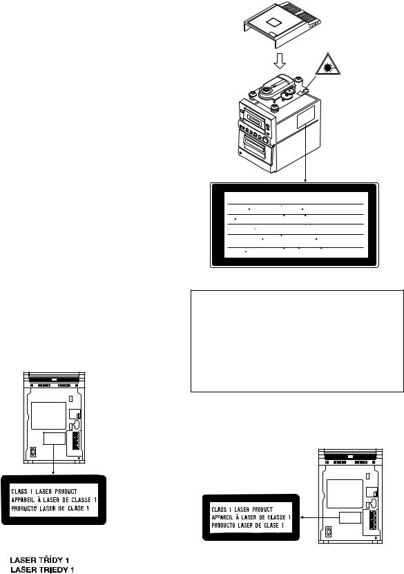
Precaution to be taken when replacing and servicing the Laser Pickup.
The AEL (Accessible Emission Level) of Laser Power Output for this model is specified to be lower than Class I Requirements. However, the following precautions must be observed during servicing to protect your eyes against exposure to the Laser beam
(1)When the cabinet has been removed, the power is turned on without a compact disc, and the Pickup is on a position outer than the lead-in position, the Laser will light for several seconds to detect a disc. Do not look into the Pickup Lens.
(2)The Laser Power Output of the Pickup inside the unit and replacement service parts have already been adjusted prior to shipping.
(3)No adjustment to the Laser Power should be attempted when replacing or servicing the Pickup.
(4)Under no circumstances look directly into the Pickup Lens at any time.
(5)CAUTION - Use of controls or adjustments, or performance of procedures other than those specified herein may result in hazardous radiation exposure.
(XL-505H) |
CAUTION-INVISIBLE LASER RADIATION WHEN OPEN. DO NOT STARE INTO
BEAM OR VIEW DIRECTLY WITH OPTICAL INSTRUMENTS.
VARNING-OSYNLIG LASERSTRALNING NAR DENNA DEL AR OPPNAD. STIRRA
EJ IN I STRALEN OCH BETRAKTA EJ STRALEN MED OPTISKA INSTRUMENT.
ADVERSEL-USYNLIG LASERSTRALING VED ABNING. SE IKKE IND I
STRALEN-HELLER IKKE MED OPTISKE INSTRUMENTER.
VARO! AVATTAESSA OLET ALTTIINA NAKYMATON LASERSATEILYLLE.
ALA TUIJOTA SATEESEEN ALAKA KATSO SITA OPTISEN LAITTEEN LAPI.
VARNING-OSYNLIG LASERSTRALNING NAR DENNA DEL AR OPPNAD.
STIRRA EJ IN I STRALEN OCH BETRAKTA EJ STRALEN GENOM OPTISKT
INSTRUMENT.
ADVERSEL-USYNLIG LASERSTRALING NAR DEKSEL APNES. STIRR IKKE
INN I STRALEN ELLER SE DIREKTE MED OPTISKE INSTRUMENTER.
VAROITUS! LAITTEEN KÄYTTÄMINEN MUULLA KUIN TÄSSÄ
KÄYTTÖOHJEESSA MAINITULLA TAVALLA SAATTAA ALTISTAA KÄYTTÄJÄN TURVALLISUUSLUOKAN 1 YLITTÄVÄLLE NÄKYMÄTTÖMÄLLE LASERSÄTEILYLLE.
VARNING - OM APPARATEN ANVÄNDS PÅ ANNAT SÄTT ÄN I DENNA BRUKSANVISNING SPECIFICERAS. KAN A NV ÄN DAR EN U TSÄ TT AS F ÖR OS YNL IG LASERSTRÅLNING, SOM ÖVERSKRIDER GRÄNSEN FÖR LASERKLASS 1.
(XL-505E/507E)
LASER KLASSE 1 LUOKAN 1 LASERLAITE KLASS 1 LASERAPPARAT
– 2 –
XL-505H,505E,507E/CP-505,505E,507
IMPORTANT SERVICE NOTES (XL-505E FOR UK/XL-507E ONLY)
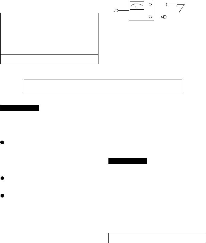
Before returning the unit to the customer after completion of a repair or adjustment it is necessary for the following withstand voltage test to be applied to ensure the unit is safe for the customer to use.
Setting of Withstanding Voltage Tester and set.
Set name |
set value |
|
|
Withstanding Voltage Tester |
|
|
|
Test voltage |
4,240 VPEAK |
|
3,000 VRMS |
|
|
Set time |
6 secs |
|
|
Set current(Cutoff current) |
4 mA |
|
|
Unit |
|
|
|
Judgment |
|
OK: The “GOOD” lamp lights.
NG: The “NG” lamp lights and the buzzor sounds.
WITHSTANDING
VOLTAGE TESTER
PROBE
+
AC
OUT |
|
|
|
- |
|
UNIT |
|
|
|
||
|
|
|
|
SHORT-CIRCUIT |
CONNECT THE PROBE |
||
AC POWER |
TO GND TERMINOF CHASSISL |
||
SUPPLY CORD |
OF PHONO TERMINAL |
||
SCREW |
|||
FOR A COMPLETE DESCRIPTION OF THE OPERATION OF THIS UNIT, PLEASE REFER TO THE OPERATION MANUAL.
SPECIFICATIONS
XL-505H/505E/507E
 General
Power source: |
AC 230 V, 50 Hz |
Power consumption: |
52 W |
Dimensions: |
Width; 160 mm (6-5/16") |
|
Height; 240 mm (9-1/2") |
|
Depth; 250 mm (9-7/8") |
Weight: |
2.6 kg (5.7 lbs.) |
Amplifier section |
|
Output power: |
PMPO; 28 W (total) |
(XL-505H/505E) |
MPO; 14 W (7 W + 7 W) (DIN 45 324) |
|
RMS; 10 W (5 W + 5 W) (DIN 45 324) |
Output power: |
MPO; 14 W (7 W + 7 W) (10 % T.H.D.) |
(XL-507E) |
RMS; 10 W (5 W + 5 W) (10 % T.H.D.) |
Output terminals: |
Speakers; 4 ohms |
|
Headphones; 16-50 ohms |
Tuner section |
(recommended; 32 ohms) |
|
|
Frequency range: |
FM; 87.5 - 108 MHz |
|
AM; 522 - 1,620 kHz |
Compact disc player section |
|
Type: |
Compact disc player |
Signal readout: |
Non-contact, 3-beam semi-conductor |
|
laser pickup |
D/A Converter: |
1-bit D/A converter |
Filter: |
8-times oversampling digital filter |
Frequency response: |
20 - 20,000 Hz |
Wow and flutter: |
Unmeasurable |
|
(less than 0.001% W.peak) |
 Cassette deck section
Frequency response: |
50 - 14,000 Hz (Normal tape) |
Signal/noise ratio: |
55 dB |
(XL-505H/505E) |
|
Signal/noise ratio: |
50 dB |
(XL-507E) |
|
Wow and flutter: |
0.3 % (DIN 45 511) |
(XL-505H/505E) |
|
Wow and flutter: |
0.25 % (WRMS) |
(XL-507E) |
|
CP-505/505E/507
Type: |
Full range speaker system |
Speakers: |
10 cm (4") full-range speaker |
Rated input power: |
5 W |
Maximum input power: |
10 W |
Impedance: |
4 ohms |
Dimensions: |
Width; 145 mm (5-3/4") |
(CP-505/507) |
Height; 240 mm (9-1/2") |
|
Depth; 183 mm (7-1/4") |
Dimensions: |
Width; 145 mm (5-3/4") |
(CP-505E) |
Height; 240 mm (9-1/2") |
|
Depth; 133 mm (5-1/4") |
Weight: |
1.1 kg (2.4 lbs.)/each |
(CP-505/507) |
|
Weight: |
1.0 kg (2.2 lbs.)/each |
(CP-505E) |
|
Specifications for this model are subject to change without prior notice.
– 3 –
XL-505H,505E,507E/CP-505,505E,507
NAMES OF PARTS
XL-505H/505E/507E

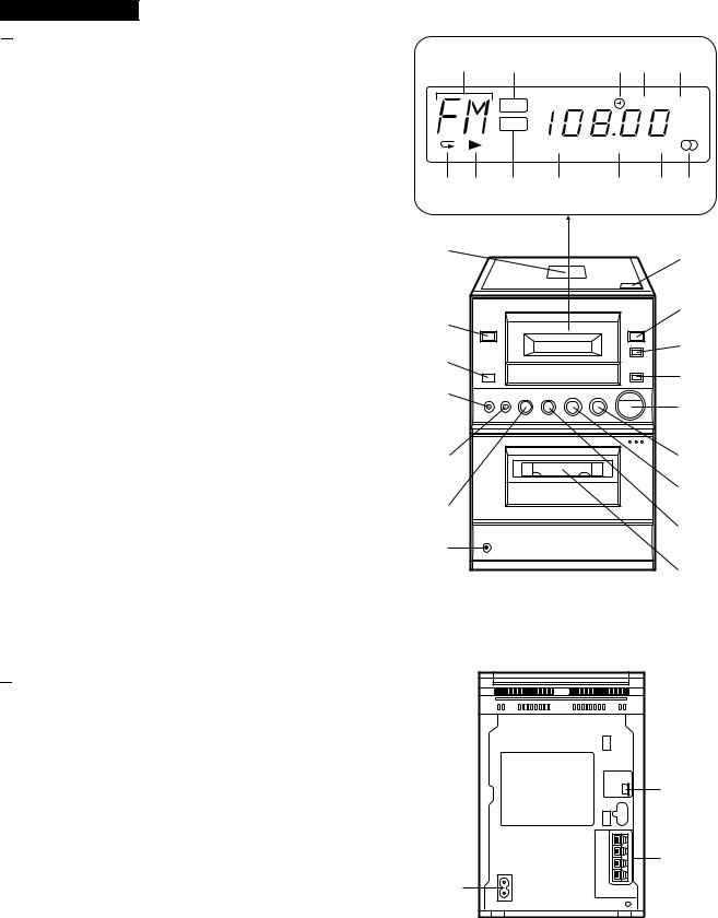
 Front Panel
1.Function/Band/Track Number Indicator
2.Volume Indicator
3.Timer Indicator
4.Record Indicator
5.Sleep Indicator
6.Repeat Indicator
7.Play Indicator
8.Extra Bass/Equalizer Indicator
9.Random Indicator
10.Memory Indicator
11.FM Stereo Mode Indicator
12.FM Stereo Indicator
13.CD Compartment
14.On/Stand-by Switch
15.Remote Control Sensor
16.Record Pause/Beat Cancel Button
17.Memory/Set Button
18.(CD) Track Down/Review Button (TAPE) Rewind Button
(TUNER) Preset Down Button
19.Headphones Socket
20.CD Eject Button
21.Function Selector Button
22.Band Selector Button
23.Extra Bass/Equalizer Mode Button
24.Volume Up/Down Buttons
25.(CD) Play/Pause Button (TAPE) Play Button (TUNER) Tuning Up Button
26.(CD/TAPE) Stop Button (TUNER) Clear Button
27.(CD) Track Up/Cue Button (TAPE) Fast Forward Button (TUNER) Preset Up Button
28.Cassette Compartment

 Rear Panel
1.AC Power Input Socket
2.FM/AM Loop Aerial Socket
3.Speaker Terminals
1 |
2 |
3 |
4 |
5 |
|
VOL |
|
REC SLEEP |
|
EQ |
kHz |
|
MHz |
||
|
|
|
|
RANDOM |
MEMORY |
ST |
6 |
7 |
8 |
9 |
10 |
11 12 |
13 |
|
|
|
|
20 |
14 |
|
|
|
|
21 |
|
|
|
|
|
|
15 |
|
|
|
|
22 |
|
|
|
|
23 |
|
16 |
|
|
|
|
|
|
|
|
|
24 |
|
|
|
|
|
|
|
17 |
|
|
|
|
25 |
18 |
|
|
|
|
26 |
|
|
|
|
27 |
|
19 |
|
|
|
|
|
|
|
|
|
|
|
|
|
|
|
|
28 |
2 |
3 |
1 |
– 4 –

CP-505/505E/507

 Speaker Section
1.Full-Range Speaker
2.Bass Reflex Duct
3.Speaker Wire
XL-505H/505E/507E

 Remote Control
1.Remote Control Transmitter LED
2.On/Stand-by Button
3.(CD) Repeat/Random Button
4.(CD/TUNER) Memory/Set Button
5.(CD/TUNER) Clear Button
6.Timer/Set Button
7.Sleep Button
8.(CD/TAPE) Stop Button
9.(CD) Play/Pause Button (TAPE) Play Button
10.(CD) Track Up/Cue Button (TAPE) Fast Forward Button (TUNER) Preset Up Button
11.(CD) Track Down/Review Button (TAPE) Rewind Button
(TUNER) Preset Down Button
12.Tuning Up/Down Buttons
13.Timer Button
14.Timer Up/Down Buttons
15.Function Selector Button
16.Band Selector Button
17.Extra Bass/Equalizer Mode Button
18.Volume Up/Down Buttons
XL-505H,505E,507E/CP-505,505E,507
1
2
3
1
|
|
|
|
8 |
|
2 |
ON/ |
|
|
9 |
|
|
STAND-BY |
|
|
||
3 |
/RANDOM |
PRESET |
10 |
||
4 |
MEMORY/ |
TUNING |
11 |
||
SET |
|||||
|
|
|
|||
5 |
CLEAR |
TIMER/ |
|
12 |
|
SET TIMER |
|||||
6 |
SLEEP |
TIMER |
13 |
||
|
|
|
|||
7 |
FUNCTION |
BAND |
X-BASS/ |
14 |
|
EQUALIZER |
17 |
||||
|
|
||||
|
|
|
|
||
15 |
|
VOLUME |
18 |
||
|
|
||||
|
|
|
|
||
16 |
|
|
|
|
|
– 5 –

– 6 –
SETTING THE CLOCK
In this example, the clock is set for the 24-hour (0:00) system.
ON/ 
 STAND-BY


MEMORY/ |
PRESET |
|
SET |
( / |
) |
ON/ |
|
|
STAND-BY |
PRESET |
|
MEMORY/ |
( |
/ ) |
|
|
|
SET |
|
|
2
3
0:00 
 AM 12:00
4
5
6
7
8
1 |
Press the ON/STAND-BY switch to enter the stand-by mode. |
|||
2 |
Press the MEMORY/SET button. |
|||
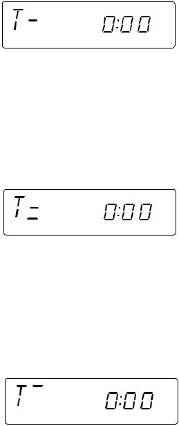
3 |
Press the PRESET ( |
or |
) button to select the time display |
|
|
mode. |
|
|
|
|
"0:00" |
→ The 24-hour display will appear. |
||
|
|
(0:00 - 23:59) |
||
|
"AM 12:00" → The 12-hour display will appear. |
|||
|
|
(AM 12:00 - PM 11:59) |
||
|
Note that this can only be set when the unit is first installed |
|||
4 |
or it has been reset (see page 14). |
|||
Press the MEMORY/SET button. |
||||
5 |
Press the PRESET ( |
or |
) button to adjust the hour. |
|
|
Press the PRESET button once to advance the time by 1 hour. |
|||
|
Hold it down to advance continuously. |
|||
|
When the 12-hour display is selected, "AM" will change auto- |
|||
6 |
matically to "PM". |
|
|
|
Press the MEMORY/SET button. |
||||
7 |
Press the PRESET ( |
or |
) button to adjust the minutes. |
|
|
Press the PRESET button once to advance the time by 1 |
|||
|
minute. Hold it down to change the time in 5 minute intervals. |
|||
|
The hour setting will not advance even if minutes advance from |
|||
8 |
"59" to "00". |
|
|
|
Press the MEMORY/SET button. |
||||
|
The clock starts operating from "0" seconds. (Seconds are not |
|||
|
displayed.) |
|
|
|
Note:
 In the event of a power failure or when the AC power lead is disconnected, the clock display will go out.
When the AC power supply is restored, the clock display will flash on and off to indicate the time when the power failure occurred or when the AC power lead was disconnected.
If this happens, follow the procedure below to change the clock time.
To change the clock time:
1 Press the ON/STAND-BY switch to enter the stand-by mode.
2 Perform steps 4 - 8 above.
To change the time display mode:
1 Perform steps 1 - 3 in the section "RESETTING THE MICROCOMPUTER", on page 14.
2 Perform steps 1 - 8 above.
PREPARATION FOR USE
0.2 m - 6 m (8" - 20')
15 |
15 |
Notes concerning use:
 Replace the batteries if control distance decreases or operation becomes erratic.
 Periodically clean the transmitter LED on the remote control and the sensor on the main unit with a soft cloth.
 Exposing the sensor on the main unit to strong light may interfere with operation. Change the lighting or the direction of the unit.
 Keep the remote control away from moisture, excessive heat, shock, and vibrations.
RESETTING THE MICROCOMPUTER
1 


3
3 


 2,3
2,3
Reset the microcomputer under the following conditions:
 To erase all of the stored memory contents (clock and timer settings, tuner and CD presets).
 If the display is not correct.
 If the operation is not correct.
1 Press the ON/STAND-BY switch to enter the stand-by mode.
2 Unplug the AC power lead from the AC INPUT socket on this unit.
3 Whilst pressing down the MEMORY/SET button and the X- BASS/EQUALIZER button, plug the AC power lead into the AC INPUT socket on this unit.
Caution:
 The operation explained above will erase all data stored in memory, such as clock and timer settings, tuner and CD presets.
MANUAL OPERATION
505,505E,507-505H,505E,507E/CP-XL
XL-505H,505E,507E/CP-505,505E,507
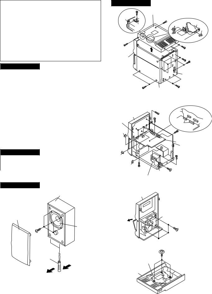
DISASSEMBLY
Caution on Disassembly
Follow the below-mentioned notes when disassembling the unit and reassembling it, to keep it safe and ensure excellent performance:
1.Take cassette tape and compact disc out of the unit.
2.Be sure to remove the power supply plug from the wall outlet before starting to disassemble the unit.
3.Take off nylon bands or wire holders where they need be removed when disassembling the unit. After servicing the unit, be sure to rearrange the leads where they were before disassembling.
4.Take suffcient care on static electricity of integrated circuits and other circuits when servicing.
XL-505H/505E/507E
STEP |
REMOVAL |
|
PROCEDURE |
|
FIGURE |
|
|
|
|
|
|
1 |
Top Cabinet |
1. |
Screw ................... |
(A1) x4 |
7-1 |
|
|
2. Socket .................. |
(A2) x3 |
|
|
|
|
3. Screw ................... |
(A3) x1 |
|
|
|
|
|
|
|
|
2 |
Side Panel |
1. Screw ................... |
(B1) x7 |
7-1 |
|
|
(Left/Right) |
|
|
|
|
|
|
|
|
|
|
3 |
Back Board |
1. Screw ................... |
(C1) x2 |
7-1 |
|
4 |
Front Panel |
1. |
Screw ................... |
(D1) x9 |
7-2 |
|
|
2. Socket .................. |
(D2) x2 |
|
|
|
|
|
|
|
|
5 |
Main PWB/ |
1. Screw ................... |
(E1) x1 |
7-2 |
|
|
Display PWB/ |
2. |
Socket .................. |
(E2) x3 |
|
|
CD Servo PWB |
|
|
|
|
|
|
|
|
|
|
6 |
Power Supply PWB |
1. Screw ................... |
(F1) x4 |
7-2 |
|
|
|
|
|
|
|
7 |
Tape Mechanism |
1. |
Screw ................... |
(G1) x4 |
7-3 |
|
|
|
|
|
|
8 |
CD Mechanism |
1. |
Screw ................... |
(H1) x3 |
7-4 |
|
|
|
|
|
|
CP-505/505E/507
STEP |
REMOVAL |
PROCEDURE |
|
FIGURE |
|
|
|
|
|
1 |
Speaker |
1. Net ....................... |
(A1) x1 |
7-5 |
|
|
2. Screw .................. |
(A2) x4 |
|
|
|
|
|
|
CP-505/505E/507
Speaker Box
Net (A1x1)
(A2)x4 |
|
ø4x15mm |
Speaker |
XL-505H/505E/507E
(A3)x1 |
Top Cabinet |
|
|
|
|
ø3x10mm |
|
|
|
||
Top |
|
(A1)x1 |
|
|
|
Cabinet |
|
ø3x10mm |
|
CD |
|
|
|
|
|
||
|
|
|
|
|
|
|
Swicth |
|
(A2)x2 |
Mechanism |
|
|
|
|
|
||
|
PWB |
|
|
|
(A2)x1 |
|
|
|
|
|
|
(A1)x1 |
|
|
(A1)x2 |
|
|
|
|
ø3x10mm |
|
||
ø3x10mm |
|
|
|
||
|
|
|
|
|
|
|
|
|
(B1)x3 |
|
|
Front |
|
|
ø3x10mm |
|
|
|
|
|
|
|
|
Panel |
|
|
|
(B1)x2 |
|
|
|
|
|
ø3x10mm |
|
|
|
|
Rear Panel |
|
|
|
(B1)x2 |
Side Panel |
(C1)x2 |
|
|
|
|
ø3x10mm |
|
|
|
|
ø3x10mm |
|
|
||
|
|
|
|
||
|
|
Figure 7-1 |
|
|
|
|
|
(D1)x6 |
|
|
|
|
|
ø3x10mm |
Main |
|
|
|
|
|
|
|
|
Front Panel |
|
|
PWB |
|
|
Display PWB |
|
(E1)x1 |
|
|
|
|
ø3x10mm |
|
|
CD Servo |
|
|
|
(E2)x2 |
|
||
|
|
|
|
PWB |
|
|
|
|
|
|
|
(D2)x1 |
|
|
(D1)x1 |
|
|
|
|
|
|
|
|
|
|
|
ø3x10mm |
|
|
|
|
|
CD Servo PWB |
|
|
|
|
|
Main PWB |
|
|
(D2)x1 |
|
|
(F1)x3 |
|
|
|
|
|
ø4x8mm |
|
|
(E2)x1 |
|
|
(F1)x1 |
|
|
(D1)x2 |
|
|
|
||
ø3x10mm |
|
ø3x10mm |
|
|
|
Power Supply
Power PWB
Transformer
Figure 7-2
Front Panel
Open |
Tape Mechanism |
(G1)x4
ø3x10mm
Figure 7-3
|
(H1)x3 |
Screw |
ø2.6x10mm |
|
|
driver |
CD Mechanism |
|
Top Cabinet
Direction of handle
Figure 7-5
Figure 7-4
– 7 –
XL-505H,505E,507E/CP-505,505E,507
REMOVING AND REINSTALLING THE MAIN PARTS
CD MECHANISM SECTION
Perform steps 1 and 8 of the disassembly method to remove the CD mechanism.
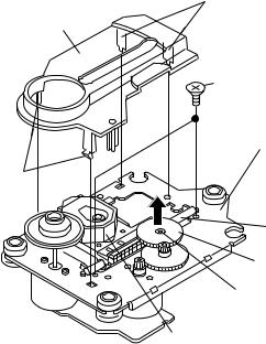
How to remove the pickup (See Fig. 8)
1.Remove the mechanism cover, paying attention to the pawls (A1) x 4 pcs.
2.Remove the screws (A2) x 2 pcs., to remove the shaft (A3) x 1 pc.
3.Remove the stop washer (A4) x 1 pc., to remove the gear (A5) x 1 pc.
4.Remove the pickup.
Note:
After removing the optical pickup connector wrap the front end of connector in conductive aluminium foil so as to prevent damage of optical pickup by static electricity.
( A1 ) x2
Mechanism Cover
( A2 ) x2 ø2.6 x6mm
CD Mechanism
( A1 )
Shaft
( A3 ) x1
Gear
( A5 ) x1
StopWasher ( A4 ) x1
Pickup Unit
Figure 8
– 8 –

XL-505H,505E,507E/CP-505,505E,507
ADJUSTMENT
MECHANISM SECTION
• Driving Force Check
Torque Meter |
Specified Value |
|
|
Play: TW-2412 |
Over 80 g |
|
|
• Torque Check
Torque Meter |
Specified Value |
|
|
Play: TW-2111 |
30 to 70 g. cm |
|
|
Fast forward: TW-2231 |
50 to 140 g.cm |
|
|
Rewind: TW-2231 |
50 to 140 g.cm |
|
|
• Tape Speed
Test Tape |
Adjusting |
Specified |
Instrument |
|
Point |
Value |
Connection |
|
|
|
|
MTT-111 |
In Motor |
3,000 ± |
Headphones |
|
|
|
90 Hz |
|
|
|
|
TAPE MECHANISM
M901
Motor
Volume in motor
Figure 9-1 ADJUSTMENT POINT
|
T302 |
|
|
|
CNP301 |
|
T306 |
AM BAND |
|
ANTENNA |
AM |
|
COVERAGE |
|
|
|
|
||
|
|
|
|
|
|
TRACKING |
|
|
|
|
|
|
|
TP302 |
|
L302 |
|
|
|
|
FM BAND |
|
|
FM MUTE |
|
COVERAGE |
|
|
|
|
TP301 |
LEVEL |
||
|
1 |
|||
|
|
|||
|
T304 |
|
|
|
|
|
|
T351 |
|
|
|
FM IF |
|
|
|
|
VR351 |
||
|
|
|
||
|
IC301 |
L303 FM RF |
AM IF |
|
|
|
|||
MAIN PWB
TUNER SECTION
fL: Low-range frequency fH: High-renge frequency
• FM RF
Signal generator: 1 kHz, 75 kHz dev., FM modulated
Test Stage |
Frequency |
Frequency |
Setting/ |
Instrument |
|
|
|
|
Display |
Adjusting |
Connection |
|
|
|
|
Parts |
|
Band |
— |
|
87.50 MHz |
(fL): L303 |
*1 |
Coverage |
|
|
|
3.4 ± 0.1 V |
|
|
|
|
|
|
|
RF |
98.00 MHz |
98.00 MHz |
L302 |
*2 |
|
|
(10~30 dB) |
|
|
|
|
|
|
|
|
|
|
*1. Input: Antenna, |
Output: TP301 |
|
|
||
*2. Input: Antenna, |
Output: Speaker Terminal |
|
|||
• Detection
Signal generator: 10.7 MHz, FM sweep generator
Test |
Frequency |
Frequency |
Setting/ |
Instrument |
Stage |
|
Display |
Adjusting |
Connection |
|
|
|
Parts |
|
|
|
|
|
|
IF |
10.7 MHz |
98.00 MHz |
T304(Turn |
Input: Pin 1 of |
|
|
|
the core of |
IC301 |
|
|
|
T304 fully |
Output: TP302 |
|
|
|
counter- |
|
|
|
|
clockwise. |
|
• AM IF/RF
Signal generator: 400 Hz, 30%, AM modulated
Test Stage |
Frequency |
Frequency |
Setting/ |
Instrument |
||
|
|
|
|
Display |
Adjusting |
Connection |
|
|
|
|
|
Parts |
|
IF |
|
450 kHz |
|
1,620 kHz |
T351 |
*1 |
|
|
|
|
|
|
|
Band |
— |
|
522 kHz |
(fL): T306 |
*2 |
|
Coverage |
|
|
|
1.1 ± 0.1 V |
|
|
|
|
|
|
|
|
|
Tracking |
990 kHz |
|
990 kHz |
(fL): T302 |
*1 |
|
|
|
|
|
|
|
|
*1. |
Input: Antenna, |
Output: Speaker Terminal |
|
|||
*2. |
Input: Input is not connected, Output: TP301 |
|||||
• Setting the Test Mode
Keeping the BAND button and MEMORY button pressed, turn on POWER. Then, the frequency is initially set in the memory as shown in Table. Call it with the  ,
, button to use it for adjustment and check of tuner circuit.
Preset No. |
|
FM |
Preset No. |
AM |
|
||
|
|
|
|
|
|
|
|
1 |
87.50 |
MHz |
6 |
522 kHz |
|
||
2 |
108.00 |
MHz |
7 |
1,620 kHz |
|
||
3 |
98.00 |
MHz |
8 |
603 kHz |
|
||
4 |
90.00 |
MHz |
9 |
1,404 kHz |
|
||
5 |
106.00 |
MHz |
10 |
990 kHz |
|
||
11~40 |
|
|
|
|
|
|
|
|
|
|
|
|
|
|
|
|
|
|
|
|
|
|
|
|
|
|
|
|
|
|
|
• FM Mute Level
Signal generator: 1 kHz, 40 kHz dev., FM modulated
Frequency |
Display |
Adjusting |
Instrument |
|
|
Parts |
Connection |
|
|
|
|
98.00 MHz |
98.00 MHz |
VR351*1 |
Input: CNP301 |
|
(25 dBμV) |
|
Output: Speaker |
|
|
|
Terminal |
Adjust so that an output signal appears.
Figure 9-2 ADJUSTMENT POINTS
– 9 –

XL-505H,505E,507E/CP-505,505E,507
CD SECTION
1. This CD unit need adjustment as follow.
CD Test Mode |
Adjustment Part |
Value/Adjusting Method |
Instrument Connection |
|
|
|
|
Step 1 |
VR803 (Focus Offset) |
DC + 40 mV (FEL>RFO) |
FEI (R826) and VRO |
|
|
|
(1-Pin of TP801) |
|
|
|
|
Step 4 |
VR802 (Tracking Error Balance) |
*1 (See Fig. 10-1) |
TSO (3-Pin of TP801) |
|
|
|
and VRO (1 Pin of TP801) |
|
|
|
|
*1: Adjust to obtaiin vertically symmetrical waveform (Fig. 10-1) with respect toreference DC level. The reference level is VRO (Approx DC 2.1V).
2.This CD unit have the following automatic adjustment function. Automatic adjustment item. 2-1: Focus Servo Gain (Fig. 10-2)
Focus Gain Adjustment is performed when disc is changed. 2-2: Tracking Servo Gain (Fig. 10-3)
Tracking Gain Adjustment is performed when disc is changed and disc is playbacked.
TSO
FET |
|
1 |
|
VRO |
|
|
|
1 |
SYMMETRICAL |
|
|
|
UP AND DOWN |
||
|
|
||||
|
|
|
|
|
|
|
|
|
|
|
|
2
FSO
Figure 10-1 |
Figure 10-2 |
TSO |
|
1 |
|
TS2O |
|
2 |
|
Figure 10-3
CD SERVO PWB
|
VR802 |
VR803 |
TP801 |
|||||||||
|
|
|
|
|
|
|
|
|||||
|
|
|
|
|
|
|
|
321 |
|
|
|
|
|
|
|
|
|
|
|
|
|
|
|
||
|
|
|
|
|
|
|
|
|
|
|
|
|
|
|
|
|
|
|
|
|
|
|
|||
|
TRACKING |
|
|
FOCUS |
|
3 2 1 |
|
|
||||
|
|
T N |
V |
|
||||||||
|
ERROR |
|
|
OFFSET |
|
|
||||||
|
BALANCE |
|
|
|
|
|
S C |
R |
|
|||
|
|
|
|
|
|
|
||||||
|
|
|
|
|
|
O |
O |
|
||||
|
|
|
|
|
|
|
|
|
|
|||
|
|
|
|
|
|
|
|
|
|
|||
|
|
|
|
|
|
|
|
|
|
|
|
|
Figure 10-4 ADJUSTMENT POINTS
– 10 –
XL-505H,505E,507E/CP-505,505E,507
TEST MODE
The Test Mode for this microcomputer has two variations, namely "regular Test Mode" for adjustment and measurement and "selfdiagnosis Test Mode" for self-judgment in final inspection of products.
1. Entering the Test Mode
To enter the each Test Mode, press the POWER key, holding down the following two keys in the regular standby mode (power off state). In this case only the main unit keys are valid. The Test Mode is not set even when the remote controller POWER key is turned on.
[Regular Test Mode]
1.CD Test Mode (TEST 1)
2.Tuner Test Mode (TEST 3)
3.Electronic volume Test Mode (TEST 4)
4.Timer Test Mode (TEST 5)
5.LCD Test Mode (TEST 6) [Self-diagnosis Test Mode]
1.Key input diagnosis TEST Mode (TESTA)
2.CD Test Mode (TEST 1)
1.Step 1 Mode
When the CD Test Mode is set, the following display lights, and the CD pickup slides to the innermost periphery.
After lighting for 1.5 sec
When the following operation key is pressed in this state, the following operation is performed.
"POWER" ................ |
The Test Mode is set to off, power is turned off, and the mode is changed to the regular standby mode. |
"FF/FWD" ................ |
After the pickup returns once to the innermost periphery, the pickup slides to the external periphery while |
................................. |
this key is held down. |
"REW/REV" ............. |
After the pickup returns once to the innermost periphery, the pickup slides to the internal periphery while |
................................. |
this key is held down. However, input is invalid if PU-IN is on. |
"PLAY" ..................... |
Shift to Step 2 |
"STOP" .................... |
Invalid |
*In case of mode entry the pickup is moved to the internal periphery. At this time entry of any key other than POWER key is disabled until shift of pickup to the internal periphery is completed. If PU-IN SW ON cannot be detected while waiting for 10 seconds, the slide motor is stopped, the following error is displayed, and entry of any key other than POWER key is disabled.
– 11 –
XL-505H,505E,507E/CP-505,505E,507
2.Step 2 Mode
When the PLAY key is pressed in the mode above, the laser lighting is turned on. In this state the laser is only turned on, and other operations are not performed.
When the following operation key is pressed in this state, the following operation is performed.
"POWER" ................ |
The Test Mode is set to off, power is turned off, and the mode is changed to the regular standby mode. |
"FF/FWD" ................ |
While this key is held down, the pickup slides to the external periphery. |
"REW/REV" ............. |
While this key is held down, the pickup slides to the internal periphery. However, if PU-IN is on, entry is |
................................. |
invalid. |
"PLAY" ..................... |
Shift to Step 3 |
"STOP" .................... |
Return to Step 1 |
3.Step 3 Mode
While the laser is lighting, the focus servo is turned on, and focus search is performed. If focusing failure occurs, focus search is repeated until focusing is attained.
When the following operation keys are pressed in this state, the following operations are performed.
"POWER" ................ |
The Test Mode is set to off, power is turned off, and the mode is changed to the regular standby mode. |
"FF/FWD" ................ |
While this key is held down, the pickup slides to the external periphery. |
"REW/REV" ............. |
While this key is held down, the pickup slides to the internal periphery. However, if PU-IN is on, entry is |
................................. |
invalid. |
"PLAY" ..................... |
If focusing has been attained, the process proceeds to Step 4. Unless focusing has been attained, |
................................. |
reception is inhibited. |
"STOP" .................... |
Return to Step 1 |
4.Step 4 Mode
The disc is rotated and CLV is locked while the tracking servo is off.
The time display indicates always "0:00".
When the following operation keys are pressed in this state, thefollowing operations are performed.
"POWER" ................ |
The Test Mode is set to off, power is turned off, and the mode is changed to the regular standby mode. |
"FF/FWD" ................ |
While this key is held down, the pickup slides to the external periphery. |
"REW/REV" ............. |
While this key is pressed, the pickup slides to the internal periphery. However, if PU-IN is on, entry is |
................................. |
invalid. |
"PLAY" ..................... |
Shift to Step 5 |
"STOP" .................... |
Return to Step 1 |
– 12 –
XL-505H,505E,507E/CP-505,505E,507
5.Step 5 Mode
The tracking servo is turned on, groove is traced, mute is set to off, and playback is started. Even when the outermost periphery of disc is reached in playback mode, it does not stop. The LCD display indicates playback lapse time as in case of regular CD playback.
When the following operation keys are pressed in this state, the following operations are performed.
"POWER" ................ |
The Test Mode is set to off, power is turned off, and the mode is changed to the regular standby mode. |
"FF/FWD" ................ |
While this key is held down, the pickup slides to the external periphery. |
"REW/REV" ............. |
While this key is held down, the pickup slides to the internal periphery. However, if PU-IN is on, entry is |
................................. |
invalid. |
"PLAY" ..................... |
Invalid |
"STOP" .................... |
Return to Step 1 |
Other cautions
•While the CD lid OPEN is detected, entry into any step later than Step 2 is disabled. If CD lid OPEN is detected in any step higher than Step 2, return to Step 1 is done.
•TOC IL is not performed in the Test Mode.
•The key operation, excepting that specified above, is the same as that of regular operation (CD). Only the FUNCTION key is input-inhibited.
•Syncro REC with REC key input is also invalid in this mode.
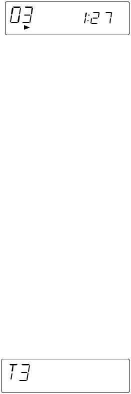
3.Tuner Test Mode (TEST 3)
1. Outline of tuner (radio) Test Mode
The tuner Test Mode is intended to store adjustment/measurement frequency in the preset memory CH without frequency adjustment by the adjusting personnel when the tuner is adjusted in the production line.
2. Details of tuner Test Mode
When power is turned on with the POWER key while the MEMORY/SET key and BAND key are held down together in POWER OFF state, the frequency for adjustment/measurement of specific destination specified by the AREA terminal is preset-stored in the preset memory CH (the frequency to be preset-stored for specific destination is explained in the Item C). When the tuner Test Mode is started up, it is started with FM. FM is FM STEREO only.
When the REW key is pressed while the preset memory CH is 1CH, the highest CH is found as in case of regular mode. When the FF key is pressed while the preset memory CH is highest CH, 1CH is found.
The RADIO (TUNER) BAND key (or TUNER/BAND key on the remote controller) is valid.
As in case of regular mode, selection of band, FM MONO/STEREO mode is enabled by pressing the RADIO (TUNER) BAND (or TUNER/BAND ) key.
Exiting the tuner Test Mode, When the destruction data is stored in the memory in the tuner Test Mode, AC supply is interrupted in the Test Mode and the AC supply is recovered, all the memory is cleared with the destruction data in case of
start-up.
(Countermeasures so that the Test Mode memory does not remain when AC supply is restored after power supply failure occurred once in the Test Mode.) The memory is not cleared when AC supply is turned off after POWER OFF and FUNCTION selection. In case of exit from the tuner Test Mode through the backup mode upon occurrence of power failure the frequency data stored in the preset memory for adjustment/measurement is erased. (As a result the preset
memory CH becomes empty.)
The display indication is the same as that in case of regular operation.
The following display lights for one second when the tuner TEST mode is turned on
– 13 –

XL-505H,505E,507E/CP-505,505E,507
Test Mode operation specification
3. Preset frequencies for various destinations (random preset memory)
|
BAND (CH) |
|
|
|
|
|
|
1 |
|
FM |
87.5MHz |
2 |
|
FM |
108.0MHz |
3 |
|
FM |
98.0MHz |
4 |
|
FM |
90.0MHz |
5 |
|
FM |
106.0MHz |
|
|
|
|
6 |
|
AM |
522 kHz |
7 |
|
AM |
1620 kHz |
8 |
|
AM |
990 kHz |
9 |
|
AM |
603 kHz |
10 |
|
AM |
1404 kHz |
|
|
|
|
•The unit used in the table above is Hz. K represents 1,000 times, and M represents 1,000,000 times.
•The hatched data shown in the table are not stored in the memory.
•FM is stereo mode.
Note: Keys which are effective in Test Mode
• Main unit keys: |
VOLUME UP/DOWN, BAND, TUNING UP, POWER, MEMORY, CLEAR, |
|
PRESET UP/DOWN |
•Remote controller keys: VOL UP/DOWN, BAND, TUNING UP/DOWN, POWER, MEMORY, CLEAR, PRESET UP/DOWN
4.Electronic volume Test Mode (TEST 4)
After the Test Mode is set, the following display lights for one second.
When this mode has been set, -14dB (STEP17) is set, the preset equalizer is set to FLAT (EQ-3), the SRS mode is set to OFF, and the start-up function is set to Tape.
1.The display is the same as that indicated in case of regular operation excepting when Test Mode is set.
2.The volume control with the Volume UP/DOWN key is only the following 3 steps, differing from the volume control in the regular
operation mode.
Volume — ∞ (STEP 0) 
 Volume — 14dB (STEP 17)
 Volume — 0 (STEP 24)
3.The preset equalizer and SRS are switched if key operation is performed.
5.Timer Test Mode (TEST 5)
When the Test Mode is set, the following display lights for one second.
The current time and timer time are set in the following procedure, and timer playback is performed.
1.The present time is set to 1:00, the timer is set to ON time 1:02, OFF time 1:12, Function is set to Tape, Volume is set to STEP8. One minute is counted in increments of second, and timer playback is performed. One step of Fade-in/out in this mode is performed for 0.5 sec.
The display is the same as that appears in the regular timer operation.
2.After completion of timer playback test "TEST-5" indication (which appears when the mode is set) appears again and Standby state is set. PLAY key entry is waited. If an entry is detected, the SLEEP timer is set to 2 minutes, and Function is set to Tape, so that playback is started at once. Volume is set to STEP8, and 10 seconds are counted down in decrements of second. One step of Fade-out is 0.5 sec.
The display is the same as that appears in the regular sleep playback mode.
3.After completion of SLEEP test, the Test Mode is turned off, and regular standby mode is set, so that the Test Mode ends.
– 14 –
XL-505H,505E,507E/CP-505,505E,507
6.LCD Test Mode (TEST 6)
When the LCD Test Mode is set, all the LCD segments light.
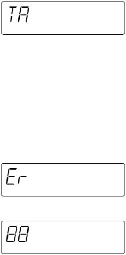
7.Key input diagnosis Test Mode (TEST A)
When the Test Mode is set, the following display appears.
In this Test Mode checking as to whether all the main unit keys can be detected is performed. Accordingly, when this mode is set, checking is performed so as to examine whether the POWER key was pressed last after all the following keys were pressed. If the result is OK, the following OK is displayed. If any one of keys was not pressed, an error is indicated. When the POWER key is pressed, exit from the mode is made irrespective of whether the termination is normal or abnormal, and the standby mode is set.
All the models using this microcomputer do not have the same keys. The entry of the following keys is detected depending on the combination of simultaneously pressed keys when this mode is set. Key pressing order is not fixed. Pressing of all keys must be detected.
1.In case of "PLAY" + "REC PAUSE"
Since the model does not have RDS and SRS, all the keys to be detected are the following 11 keys. PLAY, VOL <, VOL< , BAND, G-EQ, FUNCTION, MEMORY/SET, REC PAUSE, REW/REV, FF/FWD, STOP
OK/NG indication of test result must be as follows.
NG indication
OK indication
– 15 –

XL-505H,505E,507E/CP-505,505E,507 |
|
|
|
|
|
|
|
|
|
|
|
|
|
|
|
|
|
|
|
|
|
|||||
|
|
|
|
|
|
|
|
|
|
|
|
|
LCD |
|
|
|
|
|
|
|
|
|
|
|
|
|
|
|
|
|
|
|
|
|
|
|
|
|
|
LCD701 |
|
|
|
|
|
|
|
|
|
|
|
||
|
|
|
|
|
|
|
|
|
|
|
|
|
|
|
|
|
|
|
93 |
~ |
74 |
|
|
|
|
|
|
|
|
|
|
|
|
|
1 |
COM3 |
|
|
|
|
|
|
|
|
|
SEG7 |
~ |
SEG26 |
|
|
|
|
|
|
|
|
|
|
|
|
|
|
|
|
|
|
|
|
|
|
|
|
|
|
|
|
||||
|
|
|
|
|
|
|
|
~ |
~ |
|
|
|
|
|
|
|
|
|
|
|
|
|
|
|
||
|
|
|
|
|
|
|
|
4 |
COM0 |
|
|
|
|
|
|
|
|
|
|
|
|
|
|
|
|
|
|
|
|
|
|
|
|
|
5 |
VLC3 |
|
|
|
|
|
|
|
|
|
|
|
|
|
|
|
|
|
|
|
|
|
|
|
|
|
9 |
OSC2 |
|
|
|
|
IC701 |
|
|
|
|
|
|
|
|
|
|
||
|
|
|
|
|
|
|
|
10 |
OSC1 |
|
|
|
|
|
|
|
|
|
|
|
|
|
|
|||
|
|
|
|
|
|
|
X701 |
11 |
VSS |
|
|
|
IX0189AW |
|
|
|
|
|
|
|
|
|
||||
|
|
|
|
|
|
|
|
|
|
|
|
|
|
|
|
|
|
|
|
|||||||
|
|
|
|
|
|
|
|
12 |
XI |
|
|
|
|
|
|
|
|
|
|
|
|
|
|
|
|
|
|
|
|
|
|
|
|
X702 |
13 |
XO |
|
|
|
|
|
|
|
|
|
|
|
|
|
|
|
|
|
|
|
|
|
|
|
|
14 |
MMOD |
|
|
|
|
|
|
|
|
|
|
|
|
|
|
|
|
|
|
|
|
|
|
|
|
|
|
15 |
VREF |
|
|
|
|
|
|
|
|
|
|
|
|
|
|
|
BUS3 62 |
|
|
|
|
|
|
KEY |
|
|
|
|
|
|
|
|
|
|
|
|
|
|
|
|
|
|
|
||
|
|
|
|
|
|
|
17 |
KEY1 |
|
|
|
|
|
|
|
|
|
|
|
|
|
|
|
~ |
~ |
|
|
|
|
|
|
SW702-SW707 |
|
|
~ |
~ |
|
|
|
|
|
|
|
|
|
|
|
|
|
|
|
PU-IN |
57 |
|
|
|
|
|
SW710-SW714 |
|
|
19 |
POWER |
|
|
|
|
|
|
|
|
|
|
|
|
|
|
|
|
|
|
|
|
|
|
SW718 |
|
|
|
|
|
|
|
|
|
|
|
|
|
|
|
|
|
|
|||
|
|
|
|
|
|
|
|
|
|
|
|
|
|
|
|
|
|
|
|
|
|
|
LID-SW |
56 |
||
|
|
|
|
|
|
|
|
|
|
|
|
|
|
|
|
|
|
|
|
|
|
|
|
|||
|
|
|
|
|
|
|
|
21 |
F.P |
|
|
|
|
|
|
|
|
|
|
|
|
|
|
|
BIAS |
55 |
|
|
|
|
|
|
|
|
~ |
~ |
|
|
|
|
|
|
SYS STOP |
REMOCON |
|
STEREO |
|
|
|
|
B-CAN 54 |
||
LED704-LED712 |
|
|
|
|
|
|
|
23 |
CAM SW |
|
RESET |
P-MUTE |
P-CONT |
CD+B |
|
|
CD RES |
|
BUCK |
R-MUTE |
REC 53 |
|||||
|
|
|
|
|
|
|
|
|
|
CE |
CLE |
SD |
CEE |
MOT 52 |
||||||||||||
|
|
|
|
|
|
|
|
|
DI |
~ |
SOL 51 |
|||||||||||||||
|
|
|
|
|
|
|
|
|
25 |
~ |
31 |
32 |
34 |
35 |
36 |
37 |
38 |
39 |
40 |
41 |
45 |
46 |
47 |
48 |
|
|
FW701 |
|
|
|
|
|
|
|
|
|
|
|
|
|
|
|
|
|
|
|
|
|
|
|
|
|
|
|
|
|
|
|
SYS STOP |
|
|
|
|
|
|
|
|
|
|
|
|
|
|
|
|
|
|
|
|
|
|
|
|
|
|
REMOCON |
|
|
|
|
|
|
|
|
|
|
|
|
|
|
|
|
|
|
|
|
|
|
|
|
|
|
RESET |
|
|
|
|
|
|
|
|
|
|
|
|
|
|
|
|
|
|
|
|
|
|
SWITCHING |
|
|
|
|
|
|
|
|
|
|
|
|
|
|
|
|
|
|
|
|
|
|
|
|
|
Q701 |
Q702 |
|
|
|
Q704 |
M+12V |
Q705 |
|
|
|
|
|
|
|
|
|
|
|
|
|
|
|
|
|
|
|
|
Q703 |
RX701 |
|
|
|
|
|
|
|
|
|
|
|
|
|
|
|
|
|
|
|
|
|
|
||
RESET |
|
|
|
|
|
|
SWTCHING |
|
|
|
|
|
|
|
|
|
|
|
|
|
|
|
|
|
|
|
|
|
2 |
3 |
1 |
|
|
|
|
|
|
|
|
|
|
|
|
|
|
|
|
|
|
|
|
|
|
|
-CON +5V |
|
|
|
|
|
|
|
|
|
|
|
|
|
|
|
|
|
|
|
|
|
|
|
|
|
|
|
Q707 |
A 12V |
|
|
|
|
|
|
|
|
|
|
|
|
|
|
|
|
|
|
|
|
|
||
|
SWITCHING |
LED+B |
|
|
|
|
|
|
|
|
|
|
|
|
|
|
|
|
|
|
|
|
|
|||
|
|
|
|
|
|
|
|
|
|
|
|
|
|
|
|
|
|
|
|
|
|
|
|
|
||
|
|
|
|
|
|
|
|
|
|
|
|
|
|
|
|
|
|
|
|
|
|
|
|
|
|
|
P CONT
|
|
|
|
|
|
|
|
|
|
|
|
|
|
|
|
|
|
|
Q706 |
|
|
|
|
|
|
|
|
|
|
|
|
|
|
|
|
|
|
|
|
|
|
|
|
|
|
|
|
|
|
|
|
|
|
|
|
|
SWITCHING |
|
|
|
|
|
|
|
|
|
|
|
|
|
|
|
|
|
|
|
|
|
|
(S+6.2VLINE) |
|
|
|
|
|
FMSO |
|
|
|
|
|
|
|
|
|
|
|
|
|
|
|
|
|
|
|
|
|||||||
|
|
|
|
|
|
|
|
|
|
|
|
|
|
|
|
|
|
|
|
|
|
|
|
|
|
|
|
|
|
|
|
|
|
|
|||
|
|
|
|
|
SL– |
SL+ |
|
|
|
|
TR+ |
TR– |
|
|
TS2O |
|
|
|
|
|
|
|
|
|
|
|
|
|
|
|
|
|
|
|
|
||
18 |
17 |
16 |
15 |
14 |
13 |
12 |
11 |
10 |
9 |
8 |
7 |
6 |
5 |
4 |
3 |
2 |
1 |
|
|
|
|
|
|
|
|
|
|
|
|
|
|
|
|
|
|
|
|
Reg5V |
VCC |
NC |
|
|
|
|
|
|
GND |
|
|
|
|
GAIN1 |
NC |
|
–+ |
IC804 |
|
|
|
|
|
|
|
|
|
|
|
|
|
|
|
|
|
|
|
|
|
|
|
|
|
|
|
|
|
|
|
|
|
|
|
|
|
|
|
|
|
|
|
|
|
|
|
|
|
|
|||||||
|
|
+ – |
|
+ – –+ |
|
|
|
|
+ – –+ |
|
– + |
|
|
|
|
|
|
|
|
|
|
|
|
|
|
|
|
|
|
|
|
|
|
|
|||
|
|
|
|
|
LEVEL |
|
|
|
|
LEVEL |
|
|
|
|
|
|
|
|
|
|
|
|
|
|
|
|
|
|
|
|
|
|
|
|
|
||
|
|
|
|
|
SHIFT |
|
|
|
|
SHIFT |
|
|
|
|
|
|
|
|
|
|
|
|
|
|
|
|
|
|
|
|
|
|
|
|
|
||
|
+ – |
|
|
|
|
|
|
|
|
|
|
|
|
|
|
|
|
|
|
|
|
|
|
|
|
|
|
|
|
|
|
|
|
|
|
|
|
|
|
|
|
|
LEVEL |
|
|
|
|
LEVEL |
|
|
|
T.S.D |
|
|
|
|
|
|
|
|
|
|
|
|
|
|
|
|
|
|
|
|
|||
|
|
|
|
|
|
+ – |
|
|
|
|
|
|
|
|
|
|
|
|
|
|
|
|
|
|
|
|
|
|
|
|
|
|
|||||
|
|
|
|
|
SHIFT |
|
|
|
|
SHIFT |
|
|
|
|
|
|
|
|
|
|
|
|
|
|
|
|
|
|
|
|
|
|
|
|
|
||
|
|
+ – |
|
+ – –+ |
|
|
|
|
+ – –+ |
|
– + |
|
STAND |
|
|
|
|
|
|
|
|
|
|
|
|
|
|
|
|
|
|
|
|
||||
|
|
|
|
|
|
|
|
|
|
|
|
GAIN4 |
|
-BY |
|
|
|
|
|
|
|
|
|
|
|
|
|
|
|
|
|
|
|
|
|||
|
|
|
|
|
|
|
|
|
GND |
VCC |
|
|
|
|
|
|
|
|
|
|
|
|
|
|
|
|
|
|
|
|
|
|
|
|
|
|
|
19 |
20 |
21 |
22 |
23 |
24 |
25 |
26 |
27 |
28 |
29 |
30 |
31 |
32 |
33 |
34 |
35 |
36 |
|
|
|
|
|
|
|
|
|
|
|
|
|
|
|
|
|
|
|
|
|
|
|
|
|
|
|
|
|
|
|
|
|
|
|
|
|
CD STB |
|
|
|
|
|
|
|
|
|
|
|
|
|
|
|
|
|
|
|
|
|
|
|
DMEO |
|
|
|
|
|
|
FO– |
FO+ |
FSO |
|
|
|
|
|
|
DMEO |
DMEN |
DMEP |
SEL |
CD+5V |
|
|
|
|
|
COSC |
|
|
|
|
|
|
||
|
|
|
SP+ |
SP– |
|
|
|
|
|
|
|
|
|
|
|
24 |
23 |
22 |
21 |
VCC |
20 |
GND |
19 |
OSCI |
18 |
17 |
FSO |
16 |
FSN |
15 |
|
||||||
|
|
|
|
|
|
|
|
|
|
|
|
|
|
DFCT 25 |
|
|
|
|
|
|
|
|
14 FEL2 |
||||||||||||||
|
|
|
|
|
|
|
|
|
|
|
|
|
|
|
|
|
|
|
|
|
|
|
|
|
|
|
|
|
|
|
|
|
|
|
|||
|
|
|
|
|
|
|
|
|
|
|
|
|
|
|
|
|
|
|
|
|
FMSO 26 |
|
|
|
|
|
|
|
|
|
|
|
|
|
|
|
FOCUS |
|
|
|
|
|
|
|
|
|
|
|
|
|
|
|
|
|
|
|
|
|
|
|
|
|
|
|
|
|
|
|
|
|
|
|
13 FEL1 OFFSET |
||
|
|
|
|
|
|
|
|
|
|
|
|
|
|
|
|
|
|
|
|
|
|
|
|
|
|
|
|
|
|
|
|
|
|
|
|
|
VR803 |
|
|
|
|
|
|
|
|
|
|
|
|
|
|
|
|
|
|
|
|
|
FMSM 27 |
|
|
|
|
|
|
|
|
|
|
|
|
|
|
12 FHLD |
|
|
SLEDM801 |
M |
+ |
|
|
|
SP+ |
|
|
|
|
|
|
|
SP+ |
|
|
FMSP 28 |
|
|
|
|
|
|
|
|
|
|
|
|
|
|
11 FEI |
||||
|
– |
|
|
|
6 |
|
6 |
|
6 |
|
|
|
|
|
|
|
|
|
|
|
|
|
|
|
|
|
|
||||||||||
|
|
|
|
|
|
|
|
SP– |
5 |
|
5 |
|
5 |
|
|
SP– |
|
|
|
|
|
|
|
|
|
|
|
|
|
|
|
|
|
|
|
||
|
|
|
|
|
|
|
|
|
SL+ |
|
|
|
|
SL+ |
|
|
|
|
|
|
|
|
|
|
|
|
|
|
|
|
|
|
|
||||
|
|
|
|
|
+ |
|
|
|
4 |
|
4 |
|
4 |
|
|
|
|
THLD 29 |
|
|
|
|
|
|
|
|
|
|
|
|
|
|
10 FEO |
||||
|
M802 |
|
|
|
|
|
SL– |
|
|
|
|
SL– |
|
|
|
|
|
|
|
|
|
|
|
|
|
|
|
|
|||||||||
|
|
M – |
|
|
|
3 |
|
3 |
|
3 |
|
|
|
|
|
|
|
|
|
|
|
|
|
|
|
|
|
|
|
|
|
||||||
SPINDLE |
|
|
|
PU-IN |
|
|
|
PU-IN |
|
|
|
TS2O 30 |
|
|
|
|
|
|
|
|
|
|
|
|
|
|
|
|
|||||||||
|
|
|
2 |
|
2 |
|
2 |
|
|
|
|
|
|
|
|
|
|
|
|
|
|
|
|
|
|
9 |
FEN |
||||||||||
SW801 |
|
|
|
|
|
GND |
1 |
|
1 |
|
1 |
|
GND |
|
|
|
|
|
|
|
|
|
|
|
|
|
|
|
|
|
|
|
|
||||
|
PU-IN |
|
|
|
|
|
|
|
|
CNP803 |
|
CNS803 |
|
BI803 |
|
|
|
|
|
TS2N 31 |
|
|
|
|
|
|
|
|
|
|
|
|
|
|
8 |
FEP |
|
|
|
|
|
|
|
|
|
|
|
|
|
|
|
|
|
|
|
TS2P 32 |
|
|
|
|
|
|
|
|
|
|
|
|
|
|
7 |
DFIN |
|||
|
|
|
|
|
|
|
|
|
|
|
|
CNS801 |
|
|
BI801 |
|
|
|
|
|
TS1N 33 |
|
|
|
|
|
|
|
|
|
|
|
|
|
|
6 SBAD |
|
TR+ |
|
|
|
|
|
|
|
TR– |
|
|
|
|
TR– |
|
|
|
TS1P 34 |
|
|
|
|
|
|
|
|
|
|
|
|
|
|
5 RFRP |
|||||
|
|
|
|
|
|
|
1 |
|
1 |
|
|
1 |
|
|
|
|
|
|
|
|
|
|
|
|
|
|
|
|
|
|
|
|
|||||
FO+ |
|
|
|
|
|
|
|
TR+ |
|
|
|
TR+ |
|
|
|
TSO 35 |
|
|
|
|
|
|
|
|
|
|
|
|
|
|
4 2VRO |
||||||
|
|
|
|
|
|
|
2 |
|
2 |
|
|
2 |
|
|
|
|
|
|
|
|
|
|
|
|
|
|
|
|
|
||||||||
FO– |
|
|
|
|
|
|
|
FO+ |
3 |
|
3 |
|
|
3 |
FO+ |
|
|
|
|
|
|
|
|
|
|
|
|
|
|
|
|
|
|
|
|
||
TR– |
|
|
|
|
|
|
|
FO– |
|
|
|
FO– |
|
|
|
TEL1 36 |
|
|
|
|
|
|
|
|
|
|
|
|
|
|
|
VRO |
|||||
|
|
|
|
|
|
|
4 |
|
4 |
|
|
4 |
|
|
|
|
|
|
|
|
|
|
|
|
|
|
|
|
|
3 |
|||||||
ACTUATOR |
|
|
|
|
|
|
|
GND |
5 |
|
5 |
|
|
5 |
GND |
|
|
|
|
|
|
|
|
|
|
|
|
|
|
|
|
|
|
|
|
||
|
|
|
|
|
|
|
PD |
|
|
|
PD |
|
|
|
TEL2 37 |
|
|
|
|
|
|
|
|
|
|
|
|
|
|
|
|
||||||
|
|
|
|
|
|
|
|
6 |
|
6 |
|
|
6 |
|
SWTCHING |
|
|
|
|
|
|
|
|
|
|
|
|
|
|
2 RFI |
|||||||
|
|
|
|
|
|
|
|
VR |
7 |
|
7 |
|
|
7 |
VR |
|
|
|
|
|
|
|
|
|
|
|
|
|
|
|
|
|
|
||||
|
|
|
|
|
|
|
|
|
|
|
|
|
|
|
|
|
|
|
|
|
|
|
|
|
|
|
|
|
|
|
|||||||
|
|
|
|
|
|
|
|
LD |
|
|
|
LD |
|
|
|
|
|
|
|
|
|
|
|
|
|
|
|
|
|
|
1 RFO |
||||||
C4A |
|
|
|
|
|
|
|
8 |
|
8 |
|
|
8 |
|
Q801 |
+5V |
TSN 38 |
|
|
|
|
|
|
|
|
|
|
|
|
|
|
||||||
|
|
|
|
|
|
|
|
|
|
|
|
|
|
|
|
|
|
|
|
|
|
|
|
|
|
|
|
|
|
|
|
|
|
|
|
|
|
1/2VCC |
VR1A |
|
|
|
|
|
|
|
|
CNS802 |
|
|
|
|
|
|
|
|
39 |
40 |
41 |
42 |
|
43 |
|
44 |
|
45 |
|
46 |
|
47 |
|
48 |
|
||
C |
|
|
|
|
|
|
|
|
|
|
|
|
|
|
|
|
|
|
|
|
|
|
|
|
|
|
|||||||||||
|
|
|
|
|
|
|
|
|
|
|
|
|
BI802 |
|
|
|
|
|
TPO |
TPI |
TNI |
TNO |
FNI |
FPI |
LDO |
MDI |
|
RFN |
|
RFT |
|
||||||
F |
|
|
|
|
|
|
|
|
|
|
|
|
|
|
|
|
|
|
|
|
|
||||||||||||||||
|
|
|
|
|
|
|
|
|
|
|
|
|
|
|
|
|
|
|
|
|
|
||||||||||||||||
B |
|
|
|
|
|
|
|
|
C |
|
|
|
|
|
|
|
|
|
|
|
|
|
|||||||||||||||
A |
|
|
|
|
|
|
|
|
1 |
|
1 |
|
|
1 |
|
|
|
|
|
|
|
TRACKING |
|
|
|
|
|
|
|
|
|
|
|
IC801 |
|||
E |
|
|
|
|
|
|
|
|
F |
|
|
|
|
|
|
|
|
|
|
ERROR |
|
|
|
|
|
|
|
|
|
|
|
|
|
||||
|
|
|
|
|
|
|
|
2 |
|
2 |
|
|
2 |
|
|
|
|
|
|
|
BLANCE |
|
|
|
|
|
|
|
|
|
|
|
|
|
|||
GND |
|
|
|
|
|
|
|
|
B |
|
|
|
|
|
|
|
|
|
|
VR802 |
|
|
|
|
|
|
|
|
|
|
|
|
|
||||
|
|
|
|
|
|
|
|
3 |
|
3 |
|
|
3 |
|
|
|
|
|
|
|
|
|
|
|
|
|
|
|
|
|
|
|
|
||||
MON |
C2A |
|
C3A |
|
|
|
|
A |
|
|
|
|
|
|
|
|
|
|
|
|
|
|
|
|
|
|
|
|
|
|
|
|
|
||||
LD |
|
|
|
|
|
4 |
|
4 |
|
|
4 |
|
|
|
|
|
|
|
|
|
|
|
|
|
|
|
|
|
|
|
|
|
|
||||
|
|
|
|
|
|
|
|
E |
|
|
|
|
|
|
|
|
|
|
|
|
|
|
|
|
|
|
|
|
|
|
|
|
|
||||
VCC |
|
|
|
|
|
|
|
|
5 |
|
5 |
|
|
5 |
|
|
|
|
|
LDO |
|
|
|
|
|
|
|
|
|
|
|
|
|
|
|
|
|
|
|
|
|
|
|
|
|
1/2V |
6 |
|
6 |
|
|
6 |
|
1/2VCC |
|
|
|
|
|
|
|
|
|
|
|
|
|
|
|
|
|
|
|||
|
|
|
|
|
|
|
|
+5V |
|
|
|
|
+5V |
|
|
|
PD |
|
|
|
|
|
|
|
|
|
|
|
|
|
|
|
|
||||
|
|
|
|
|
|
|
|
7 |
|
7 |
|
|
7 |
|
|
|
|
|
|
|
|
|
|
|
|
|
|
|
|
|
|
|
|
||||
|
|
|
|
|
|
|
|
|
|
|
|
|
|
|
|
|
|
|
|
|
|
|
|
|
|
|
|
|
|
|
|
|
|
|
|||
Figure 16 BLOCK DIAGRAM (1/4)
– 16 –
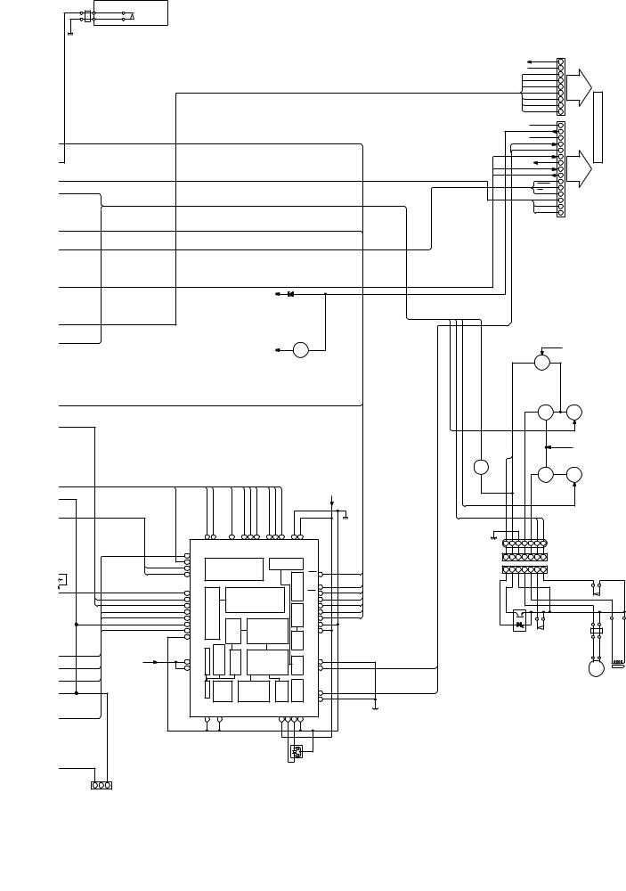
|
|
|
|
|
|
|
|
|
|
|
|
|
|
|
|
|
|
|
|
XL-505H,505E,507E/CP-505,505E,507 |
||||||||||||
FW702 |
|
|
|
|
|
|
|
|
|
|
|
|
|
|
|
|
|
|
|
|
|
|
|
|
|
|
|
|
|
|
|
|
|
|
|
SW701 |
|
|
|
|
|
|
|
|
|
|
|
|
|
|
|
|
|
|
|
|
|
|
|
|
|
|
|
|
|
|
|
|
CD EJECT |
|
|
|
|
|
|
|
|
|
|
|
|
|
|
|
|
|
|
|
|
|
|
|
|
|
|
|
|
|
|
|
|
|
|
|
|
|
|
|
|
|
|
|
|
|
|
|
|
|
|
|
|
|
|
|
|
|
|
|
CNS603 |
|
|
|
|
|
|
|
|
|
|
|
|
|
|
|
|
|
|
|
|
|
|
|
|
|
M 12V |
|
|
|
|
1 |
|
|
||
|
|
|
|
|
|
|
|
|
|
|
|
|
|
|
|
|
|
|
|
|
|
|
D GND |
VCL |
|
|
|
2 |
|
|
||
|
|
|
|
|
|
|
|
|
|
|
|
|
|
|
|
|
|
|
|
|
|
|
|
|
|
|
|
|
3 |
|
|
|
|
|
|
|
|
|
|
|
|
|
|
|
|
|
|
|
|
|
|
|
|
|
|
|
|
|
VCE |
|
|
|
|
|
|
|
|
|
|
|
|
|
|
|
|
|
|
|
|
|
|
|
|
|
|
|
|
|
|
|
|
|
|
|
4 |
|
|
|
|
|
|
|
|
|
|
|
|
|
|
|
|
|
|
|
|
|
|
|
|
|
|
|
|
|
VDI |
|
|
|
|
|
|
|
|
|
|
|
|
|
|
|
|
|
|
|
|
|
|
|
|
|
|
|
|
|
|
|
|
|
|
|
5 |
|
|
|
|
|
|
|
|
|
|
|
|
|
|
|
|
|
|
|
|
|
|
|
|
|
|
|
|
|
CL |
|
|
|
|
|
|
|
|
|
|
|
|
|
|
|
|
|
|
|
|
|
|
|
|
|
|
|
|
|
|
|
|
|
|
|
6 |
|
|
|
|
|
|
|
|
|
|
|
|
|
|
|
|
|
|
|
|
|
|
|
|
|
|
|
|
|
DO |
|
|
|
|
|
|
|
|
|
|
|
|
|
|
|
|
|
|
|
|
|
|
|
|
|
|
|
|
|
|
|
|
|
|
|
7 |
|
|
|
|
|
|
|
|
|
|
|
|
|
|
|
|
|
|
|
|
|
|
|
|
|
|
|
|
|
CE |
|
|
|
PWB |
|
|
|
|
|
|
|
|
|
|
|
|
|
|
|
|
|
|
|
|
|
|
|
|
|
|
|
|
|
|
|
8 |
|
||
|
|
|
|
|
|
|
|
|
|
|
|
|
|
|
|
|
|
|
|
|
|
|
|
|
|
DI |
|
|
|
|
||
|
|
|
|
|
|
|
|
|
|
|
|
|
|
|
|
|
|
|
|
|
|
|
|
|
|
|
|
|
9 |
|
||
|
|
|
|
|
|
|
|
|
|
|
|
|
|
|
|
|
|
|
|
|
|
|
|
|
|
|
|
|
|
|
||
|
|
|
|
|
|
|
|
|
|
|
|
|
|
|
|
|
|
|
|
|
|
|
|
|
|
|
|
|
|
|
|
|
|
|
|
|
|
|
|
|
|
|
|
|
|
|
|
|
|
|
|
|
|
|
|
|
M GND |
S+6.2V |
15 |
MAIN |
|
||||
|
|
|
|
|
|
|
|
|
|
|
|
|
|
|
|
|
|
|
|
|
|
|
|
|
|
|
14 |
|
||||
|
|
|
|
|
|
|
|
|
|
|
|
|
|
|
|
|
|
|
|
|
|
|
|
|
|
|
|
|
|
|
||
|
|
|
|
|
|
|
|
|
|
|
|
|
|
|
|
|
|
|
|
|
|
|
|
A GND |
R-CH |
|
13 |
|
||||
|
|
|
|
|
|
|
|
|
|
|
|
|
|
|
|
|
|
|
|
|
|
|
|
|
|
|
|
12 |
TO |
|
||
|
|
|
|
|
|
|
|
|
|
|
|
|
|
|
|
|
|
|
|
|
|
|
|
|
|
|
L-CH |
|
|
|||
|
|
|
|
|
|
|
|
|
|
|
|
|
|
|
|
|
|
|
|
|
|
|
|
|
|
|
|
11 |
|
|||
|
|
|
|
|
|
|
|
|
|
|
|
|
|
|
|
|
|
|
|
|
|
|
|
|
|
P MUTE |
|
|||||
|
|
|
|
|
|
|
|
|
|
|
|
|
|
|
|
|
|
|
|
|
|
|
|
|
|
10 |
|
|||||
|
|
|
|
|
|
|
|
|
|
|
|
|
|
|
|
|
|
|
|
|
|
|
|
|
|
|
|
|||||
|
|
|
|
|
|
|
|
|
|
|
|
|
|
|
|
|
|
|
|
|
|
|
|
|
|
|
|
|
|
|
|
|
|
|
|
|
|
|
|
|
|
|
|
|
|
|
|
|
|
|
|
|
|
|
|
|
A 12V |
|
|
|
9 |
|
|
||
|
|
|
|
|
|
|
|
|
|
|
|
|
|
|
|
|
|
|
|
|
|
|
|
|
|
P CONT |
8 |
|
|
|||
|
|
|
|
|
|
|
|
|
|
|
|
|
|
|
|
|
|
|
|
|
|
|
|
|
|
|
CD+B |
|
|
|||
|
|
|
|
|
|
|
|
|
|
|
|
|
|
|
|
|
|
|
|
|
|
|
|
|
|
|
7 |
|
|
|||
|
|
|
|
|
|
|
|
|
|
|
|
|
|
|
|
|
|
|
|
|
|
|
|
|
|
|
R-MUTE |
|
|
|||
|
|
|
|
|
|
|
|
|
|
|
|
|
|
|
|
|
|
|
|
|
|
|
|
|
|
|
6 |
|
|
|||
|
|
|
|
|
|
|
|
|
|
|
|
|
|
|
|
|
|
|
|
|
|
|
|
|
|
|
FM ST |
|
|
|||
|
|
|
|
|
|
|
|
|
|
|
|
|
|
|
|
|
|
|
|
|
|
|
|
|
|
|
5 |
|
|
|||
|
|
|
|
|
|
|
|
|
|
|
|
|
|
|
|
|
|
|
|
|
|
|
|
|
|
|
SD |
|
|
|
||
|
|
|
|
|
|
|
|
|
|
|
|
|
|
|
|
|
|
|
|
|
|
|
|
|
|
|
|
4 |
|
|
||
|
|
|
|
|
|
|
|
|
|
|
|
|
|
|
|
|
|
|
|
|
|
|
|
|
|
|
REC |
|
|
|
||
|
|
|
|
|
|
|
|
|
|
|
|
|
|
|
|
|
|
|
|
|
|
|
|
|
|
|
|
3 |
|
|
||
|
|
|
|
|
|
|
|
|
|
|
|
|
|
|
|
|
|
|
|
|
|
|
|
|
|
|
B-CAN |
|
|
|||
|
|
|
|
|
|
|
|
|
|
|
|
|
|
|
|
|
|
|
|
|
|
|
|
|
|
|
2 |
|
|
|||
|
|
|
|
|
|
|
|
|
|
|
|
|
|
|
|
|
|
|
|
|
|
|
|
|
|
|
BIAS |
|
|
|
||
|
|
|
|
|
|
|
|
|
|
|
|
|
|
|
|
|
|
|
|
|
|
|
|
|
|
|
|
1 |
|
|
||
|
|
|
|
|
|
|
|
|
|
|
|
|
|
|
|
|
|
|
|
|
|
|
|
|
|
|
|
|
|
|
|
|
|
|
|
|
|
|
|
|
|
|
|
|
|
|
|
|
|
|
|
|
|
|
|
|
|
|
|
|
|
|
CNS602 |
|
|
|
|
|
|
|
|
|
|
|
|
|
|
(S+6.2V) |
|
|
|
|
|
|
|
|
|
|
|
|
|
|
|
|
|
|
|
|
|
|
|
|
|
|
|
|
|
|
|
|
|
|
|
|
|
|
|
|
|
|
|
|
|
|
|
|
-CON5V |
|
|
||
|
|
|
|
|
|
|
|
|
|
|
|
|
5V |
|
|
Q861 |
|
|
|
|
|
|
|
|
|
|
|
|
|
|||
|
|
|
|
|
|
|
|
|
|
|
|
|
|
|
|
REGULATOR |
|
|
RUN PLS |
|
|
|
|
Q906 |
|
|
|
|
||||
|
|
|
|
|
|
|
|
|
|
|
|
|
|
|
|
|
|
|
|
|
|
|
|
|
|
|
|
|
|
|||
|
|
|
|
|
|
|
|
|
|
|
|
|
|
|
|
|
|
|
|
MOT |
SOL |
|
|
|
SWTCHING |
|
|
|
||||
|
|
|
|
|
|
|
|
|
|
|
|
|
|
|
|
|
|
|
|
|
|
|
|
|
|
|
|
|
|
|||
|
|
|
|
|
|
|
|
|
|
|
|
|
|
|
|
|
|
|
|
|
|
|
|
|
|
TAPE MOTOR |
SWTCHING |
|
|
|||
|
|
|
|
|
|
|
|
|
|
|
|
|
|
|
|
|
|
|
PU IN |
|
|
|
|
|
|
|
DRIVER |
|
|
|||
|
|
|
|
|
|
|
|
|
|
|
|
|
|
|
|
|
|
|
|
|
|
|
|
|
|
|
|
|
|
|
|
|
|
|
|
|
|
|
|
|
|
|
|
|
|
|
|
|
|
|
|
|
|
|
|
|
|
|
|
Q905 |
Q904 |
|
|
||
|
|
|
|
|
|
|
|
|
|
|
|
|
|
|
|
|
|
|
|
|
|
|
|
|
|
|
|
|
|
M-12V |
|
|
|
|
|
|
|
|
|
|
|
|
|
|
|
|
|
|
|
|
|
|
|
|
SWTCHING |
|
|
|
|
|
|
|
|
|
|
|
|
|
|
|
|
|
|
|
|
|
|
|
|
|
|
|
|
|
|
|
|
Q903 |
|
|
|
|
|
|
|
|
|
|
|
|
|
|
|
|
|
|
|
|
|
|
|
|
|
|
|
|
|
|
|
|
|
|
|
|
|
Q902 |
Q901 |
|
|
||
|
|
|
|
|
|
|
|
|
|
|
|
|
|
|
|
|
|
|
CD+5V |
|
|
|
|
|
|
|
SOLENOID |
SWTCHING |
|
|||
|
|
|
|
|
|
|
|
|
|
|
|
|
|
|
|
|
|
|
|
|
|
|
|
|
|
DRIVER |
|
|
|
|||
|
|
|
|
|
|
|
|
|
|
|
|
|
|
|
|
|
|
|
|
D-GND |
|
|
|
|
|
|
|
|
|
|
|
|
|
|
|
|
|
|
|
|
|
|
|
|
|
|
|
|
|
|
|
|
|
|
|
|
|
|
|
P.F |
SW |
|
|
|
|
|
|
|
|
|
|
40 |
37 |
|
36 |
34 |
33 |
32 |
30 |
28 |
27 |
|
26 |
25 |
|
|
|
|
|
|
|
|
|
CAM |
|
|
|
|
|
|
|
|
|
|
|
|
|
|
|
|
|
|
|
|
|
|
|
|
|
|
|||||||||||
|
|
|
|
|
|
DMPC |
DMFC |
|
FMFB |
FMON |
TKIC |
TGUH1 |
TGUL |
TEL1 |
TEL2 |
|
GNDD |
VDDD |
|
|
|
7 |
6 |
5 |
4 |
3 |
2 |
1 |
BI901 |
|
|
|
|
|
|
|
41 |
|
|
|
|
|
|
|
|
|
|
|
|
|
|
|
|
|
|||||||||||
|
|
|
|
2VREF |
|
|
|
|
|
|
|
|
|
|
|
|
|
|
|
7 |
6 |
5 |
4 |
3 |
2 |
1 |
CNS901 |
|
|
|||
|
|
|
|
|
SEL |
|
|
|
FOCUS |
|
|
|
|
|
TIMING |
|
|
|
|
|
|
|||||||||||
US |
|
|
|
42 |
|
|
|
|
|
|
|
|
|
|
|
|
|
|
|
|
|
|
|
|
|
|
|
|||||
SET |
|
|
|
43 |
FCSI |
|
|
TRACKING |
|
|
GENERATOR |
|
|
|
7 |
6 |
5 |
4 |
3 |
2 |
1 |
CNP901 |
|
|
||||||||
803 |
|
|
|
|
FKIC |
|
|
|
SERVO |
|
|
|
|
|
|
|
|
|
RST 21 |
RESET |
|
|
|
|||||||||
|
|
|
44 |
|
|
|
|
|
|
|
|
|
|
|
INTERFACE |
|
|
|
|
|
|
|
|
|
|
|
|
|||||
|
|
|
|
|
|
|
CONTROL |
|
|
|
|
|
|
|
|
|
|
|
|
|
|
|
|
|
|
|
|
|||||
|
|
|
|
|
|
|
|
|
|
|
|
|
|
|
CD BUS |
|
|
|
|
|
|
|
|
|
|
|
|
|
|
|||
|
|
|
|
|
|
|
|
|
|
|
|
|
|
|
|
|
BUCK 19 |
BUCK |
|
|
|
|
|
|
|
|
|
SW902 |
|
|
||
|
|
|
|
|
|
|
|
|
|
|
|
|
|
|
|
|
CCE 18 |
CCE |
|
|
|
|
|
|
|
|
|
|
|
|||
|
|
|
|
47 FEI |
|
A/D CONVERTOR |
|
|
|
|
|
|
|
|
|
|
|
|
|
|
|
|
|
|
CAM |
|
|
|||||
|
|
|
|
48 TESH |
|
|
|
|
SERVO |
|
|
|
|
BUS3 17 |
BUS3 |
|
|
|
|
|
|
|
|
|
|
|
|
|||||
|
|
|
|
|
|
|
|
|
|
|
|
|
|
|
|
|
|
|
|
|
|
|
|
|
|
|||||||
|
|
|
|
49 TEOF |
|
|
|
|
STATUS |
|
|
|
|
|
|
BUS2 16 |
BUS2 |
|
|
|
|
|
|
|
|
|
|
|
|
|||
|
|
|
|
|
|
|
|
|
|
|
|
|
|
SUB Q DATA |
|
|
|
|
|
|
|
|
|
|
|
|
|
|||||
|
|
|
|
50 SBAD |
|
|
|
|
|
|
|
|
|
|
RAM |
BUS1 15 |
BUS1 |
|
|
|
|
|
|
|
|
|
|
|
|
|||
|
|
|
|
|
|
|
|
|
|
|
|
|
|
BUS0 |
|
|
|
|
|
|
|
|
|
|
|
|
||||||
|
|
|
|
51 RFRP |
|
|
ADRESS |
|
|
|
|
|
|
|
BUS0 14 |
|
|
|
|
|
|
|
|
|
|
|
|
|||||
|
|
|
|
52 VREF |
|
|
|
|
|
|
|
|
|
|
GNDD 13 |
G-GND |
|
|
|
|
|
|
|
|
|
|
|
|
||||
|
|
|
|
53 RFI |
|
|
|
|
16K RAM |
|
|
CODE |
VDDD 12 |
|
|
|
|
|
|
|
SW901 |
FW901 |
|
|
||||||||
|
|
|
|
54 GNDA |
|
|
|
|
|
|
|
|
|
|
|
|
|
PH901 |
|
|
|
|
||||||||||
|
|
|
|
|
|
|
|
|
|
|
|
|
|
|
|
|
RECORD |
|
|
|
||||||||||||
|
|
|
|
|
|
|
CLV SERVO |
|
|
|
|
|
|
|
|
|
|
|
|
|
|
PREVENTION |
|
|
|
|||||||
|
|
|
|
|
|
STATUS |
TMAX DET |
|
|
|
|
|
|
|
|
CLOCK |
|
|
|
|
|
|
|
|
|
|
|
+ |
|
– |
||
|
|
|
CD+5V |
58 VDDA |
EFM |
|
|
CORRECT |
|
|
GNDA 7 |
CD L-CH |
|
|
|
|
|
|
|
|
|
TAPEM901 |
M |
|
||||||||
|
|
|
|
59 PDCNT |
|
|
|
|
|
|
|
LO 6 |
|
|
|
|
|
|
|
|
|
SOL901 |
||||||||||
|
|
|
|
|
|
|
|
|
|
|
|
|
|
|
|
|
|
|
|
|
|
|
|
|
|
|
|
|
|
|
|
SOLENOID |
|
|
|
|
|
|
PLL |
|
STATUS |
|
AUDIO OUT |
|
|
DIGITAL OUT |
|
DA CONV |
RO 2 |
CD R-CH |
|
|
|
|
|
|
|
|
|
|
|
|
|||
|
|
|
|
|
|
|
|
|
|
|
|
|
|
|
|
|
|
|
|
|
|
|
|
|
|
|
||||||
|
|
|
|
|
|
|
|
|
|
|
|
|
|
GNDA 1 |
|
|
|
|
|
|
|
|
|
|
|
|
|
|||||
|
|
|
|
|
|
TESTX |
GNDD |
|
|
|
|
|
|
VDDX |
|
|
GNDX |
|
A-GND |
|
|
|
|
|
|
|
|
|
|
|
|
|
|
|
|
|
|
|
|
|
|
|
|
|
XI |
XO |
|
|
|
|
|
|
|
|
|
|
|
|
|
|
|||||
|
|
|
|
|
|
65 |
67 |
|
|
|
|
|
|
77 |
78 |
79 |
80 |
IC802 |
|
|
|
|
|
|
|
|
|
|
|
|
|
|
|
|
|
|
|
|
|
|
|
|
|
|
|
|
|
|
|
|
X801 |
|
|
|
|
|
|
|
|
|
|
|
|
|
|
TSO |
|
VRO |
|
|
|
|
|
|
|
|
|
|
|
|
|
|
|
|
|
|
|
|
|
|
|
|
|
|
|
|
|
|
3 |
2 |
1 |
TP801 |
|
|
|
|
|
|
|
|
|
|
|
|
|
|
|
|
|
|
|
|
|
|
|
|
|
|
|
|
|
TEST POINT
Figure 17 BLOCK DIAGRAM (2/4)
– 17 –
 Loading...