


XL-70V
SERVICE MANUAL
No. S0082XL70V///
VIDEO CD MICRO SYSTEM
MODEL XL-70V
XL-70V Video CD Micro System consisting of XL-70V (main unit) and
CP-XL70U (speaker system).
• In the interests of user-safety the set should be restored to its original condition and only parts identical to those specified should be used.
|
This Service Manual is for the XL-70V, which is a minor-modification |
|
|
model of the XL-30V. This manual, therefore, describes only the |
|
NTSC/PAL |
|
|
|
changed points from the service manual. Please refer to the XL-30V |
|
|
service manual (No.S0081XL30V///) together with this manual. |
|
|
XL-30V |
|
|
|
Page |
|
REMOVING AND REINSTALLING THE MAIN PARTS |
...... 10 |
|
ADJUSTMENT ................................................................ |
12 |
|
WAVEFORMS OF CD CIRCUIT ..................................... |
41 |
|
TROUBLESHOOTING (CD SECTION) .......................... |
42 |
|
FUNCTION TABLE OF IC .............................................. |
49 |
CONTENTS |
|
|
Page |
SAFETY PRECAUTION FOR SERVICE MANUAL ............................................................................................................ |
2 |
VOLTAGE SELECTION ...................................................................................................................................................... |
2 |
AC POWER SUPPLY CORD AND AC PLUG ADAPTOR .................................................................................................. |
2 |
SPECIFICATIONS .............................................................................................................................................................. |
3 |
NAMES OF PARTS ............................................................................................................................................................ |
4 |
OPERATION MANUAL ....................................................................................................................................................... |
6 |
DISASSEMBLY ................................................................................................................................................................... |
8 |
TEST MODE .................................................................................................................................................................... |
10 |
ERROR LIST .................................................................................................................................................................... |
12 |
NOTES ON SCHEMATIC DIAGRAM .............................................................................................................................. |
14 |
TYPES OF TRANSISTOR AND LED ............................................................................................................................... |
14 |
VOLTAGE ........................................................................................................................................................................ |
15 |
BLOCK DIAGRAM ........................................................................................................................................................... |
16 |
SCHEMATIC DIAGRAM .................................................................................................................................................. |
22 |
WIRING SIDE OF P.W.BOARD ....................................................................................................................................... |
31 |
FUNCTION TABLE OF IC................................................................................................................................................ |
36 |
LCD SEGMENT ............................................................................................................................................................... |
38 |
PARTS GUIDE/EXPLODED VIEW |
|
SHARP CORPORATION |
This document has been published to be used |
for after sales service only. |
|
– 1 – |
The contents are subject to change without notice. |
XL-70V
SAFETY PRECAUTION FOR SERVICE MANUAL
Precaution to be taken when replacing and servicing the Laser Pickup.
The AEL (Accessible Emission Level) of Laser Power Output for this model is specified to be lower than Class 1 Requirements. However, the following precautions must be observed during servicing to protect your eyes against exposure to the Laser beam
(1)When the cabinet has been removed, the power is turned on without a compact disc, and the Pickup is on a position outer than the lead-in position, the Laser will light for several seconds to detect a disc. Do not look into the Pickup Lens.
(2)The Laser Power Output of the Pickup inside the unit and replacement service parts have already been adjusted prior to shipping.
(3)No adjustment to the Laser Power should be attempted when replacing or servicing the Pickup.
(4)Under no circumstances look directly into the Pickup Lens at any time.
(5)CAUTION - Use of controls or adjustments, or performance of procedures other than those specified herein may result in hazardous radiation exposure.
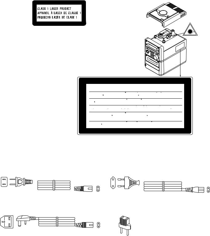
CAUTION
●This Video CD Micro System is classified as a CLASS 1 LASER product.
●The CLASS 1 LASER PRODUCT label is located on the rear cover.
●Use of controls or adjustments or performance of procedures other than those specified herein may result in hazardous radiation exposure.
As the laser beam used in this compact disc player is harmful to the eyes, do not attempt to disassemble the cabinet. Refer servicing to qualified personnel only.
Laser Diode Properties Material: GaAIAs
Wavelength: 780 nm Emission Duration: continuous Laser Output: max. 0.6 mW
CAUTION-INVISIBLE LASER RADIATION WHEN OPEN. DO NOT STARE INTO
BEAM OR VIEW DIRECTLY WITH OPTICAL INSTRUMENTS.
VARNING-OSYNLIG LASERSTRALNING NAR DENNA DEL AR OPPNAD. STIRRA
EJ IN I STRALEN OCH BETRAKTA EJ STRALEN MED OPTISKA INSTRUMENT.
ADVERSEL-USYNLIG LASERSTRALING VED ABNING. SE IKKE IND I
STRALEN-HELLER IKKE MED OPTISKE INSTRUMENTER.
VARO! AVATTAESSA OLET ALTTIINA NAKYMATON LASERSATEILYLLE.
ALA TUIJOTA SATEESEEN ALAKA KATSO SITA OPTISEN LAITTEEN LAPI.
VARNING-OSYNLIG LASERSTRALNING NAR DENNA DEL AR OPPNAD.
STIRRA EJ IN I STRALEN OCH BETRAKTA EJ STRALEN GENOM OPTISKT
INSTRUMENT.
ADVERSEL-USYNLIG LASERSTRALING NAR DEKSEL APNES. STIRR IKKE
INN I STRALEN ELLER SE DIREKTE MED OPTISKE INSTRUMENTER.
VOLTAGE SELECTION
Before operating the unit on mains, check the preset voltage. If the voltage is different from your local voltage, adjust the voltage as follows. Turn the selector with a screwdriver until the appropriate voltage number appears in the window (110/127/220/230240V AC).
AC POWER SUPPLY CORD AND AC PLUG ADAPTOR
QACCA0001SJ00 |
|
QACCE0001SJZZ |
|||||
|
|
|
|
|
|
|
|
|
|
|
|
|
|
|
|
|
|
|
|
|
|
|
|
|
|
|
|
|
|
|
|
|
|
|
|
|
|
|
|
|
|
|
|
|
|
|
|
|
|
|
|
|
|
|
|
|
|
|
|
|
|
|
|
QACCB0001SJ00
QPLGA0253AFZZ
– 2 –

XL-70V
FOR A COMPLETE DESCRIPTION OF THE OPERATION OF THIS UNIT, PLEASE REFER TO THE OPERATION MANUAL.
SPECIFICATIONS
XL-70V |
|
● General |
|
Power source: |
AC 110/127/220/230-240V, |
Power |
50/60 Hz |
|
|
consumption: |
55 W |
Dimensions: |
Width; 160 mm (6-5/16") |
|
Height; 241 mm (9-1/2") |
Weight: |
Depth; 298 mm (11-3/4") |
4.3 kg (9.5 lbs.) |
● Amplifier section
Output power: MPO; 60 W (30 W + 30 W) (10 % T.H.D.)
RMS; 40 W (20 W + 20 W) (10 % T.H.D.)
Output terminals: Speakers; 4 ohms Headphones; 16-50 ohms (recommended; 32 ohms) Video out: 1 Vp-p (75 ohms)
Input terminals: Video/Auxiliary (audio signal); 500 mV/47 kohms
● Video CD section
Video output
format: PAL / NTSC
● Compact disc player section
Type: Compact disc player
Signal readout: Non-contact, 3-beam semiconductor laser pickup
D/A converter: 1-bit D/A converter
Filter: 8-times oversampling digital filter
Frequency |
|
response: |
20 - 20,000 Hz |
Wow and flutter: |
Unmeasurable |
|
(less than 0.001% W. peak) |
●Cassette deck section Frequency
response: 50 - 14,000 Hz (Normal tape)
Signal/noise ratio: 50 dB
Wow and flutter: 0.25 % (WRMS)
●Tuner section
Frequency range: FM; 88-108 MHz AM; 531-1,602 kHz
|
CP-XL70U |
|
Type: |
2-way [10 cm (4") woofer and |
|
Rated input |
2.5 cm (1") semidome tweeter] |
|
|
||
power: |
20 W |
|
Maximum input |
|
|
power: |
40 W |
|
Impedance: |
4 ohms |
|
Dimensions: |
Width; 160 mm (6-5/16") |
|
|
|
Height; 240 mm (9-1/2") |
Weight: |
Depth; 189 mm (7-1/2") |
|
2.3 kg (5.1 lbs.)/each |
||
Specifications for this model are subject to change without prior notice.
– 3 –
XL-70V
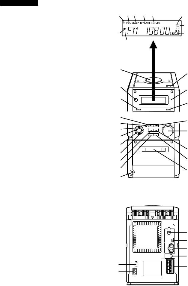
NAMES OF PARTS
XL-70V
■Front panel
1.Timer Indicator
2.Record Indicator
3.Sleep Indicator
4.(VCD/CD) Random Indicator
5.(VCD/CD/TUNER) Memory Indicator
6.FM Stereo Mode Indicator
7.(VCD/CD) Play Indicator
8.(VCD/CD) Repeat Indicator
9.FM Stereo Indicator
10.Surround Indicator
11.VCD/CD Compartment
12.On/Stand-by Button
13.Surround Button
14.(VCD/CD) Open/Close Button
15.Remote Control Sensor
16.Volume Select Button
17.(VCD) Stop/Return Button (CD/TAPE) Stop Button (TUNER) Memory Clear Button
18.(TAPE) Record Pause Button
19.Bass/Treble Selector Button
20.Memory/Set Button
21.Clock/Timer/Sleep Button
22.Band Selector Button
23.(VCD) Skip/Previous Button (CD) Track Down Button (TAPE) Rewind Button (TUNER) Tuning Down Button
24.Function Selector Button
25.Headphones Socket
26.(VCD/CD/TAPE) Play Button
27.Volume/Jog Dial
28.(VCD) Skip/Next Button (CD) Track Up Button (TAPE) Fast Forward Button (TUNER) Tuning Up Button
29.Volume/Jog Dial Selector Button
30.Cassette Compartment
1 |
2 |
3 |
4 |
5 |
6 |
|
|
|
|
|
9 |
7 |
|
|
|
|
10 |
|
8 |
|
|
|
|
11 |
14 |
|
|
||
12 |
15 |
|
|
||
13 |
16 |
|
|
||
17 |
26 |
|
18 |
||
|
||
19 |
27 |
|
20 |
|
|
21 |
28 |
|
22 |
||
29 |
||
23 |
||
|
||
24 |
30 |
|
25 |
|
■Rear panel
1.Voltage Selector
2.AC Power Input Socket
3.FM 75 ohms Aerial Socket
4.AM Loop Aerial Socket
5.Video/Auxiliary (Audio Signal) Input Sockets
6.Video Output Socket
7.Speaker Terminals
3
4
5
6
1 |
7 |
|
2 |
||
|
– 4 –
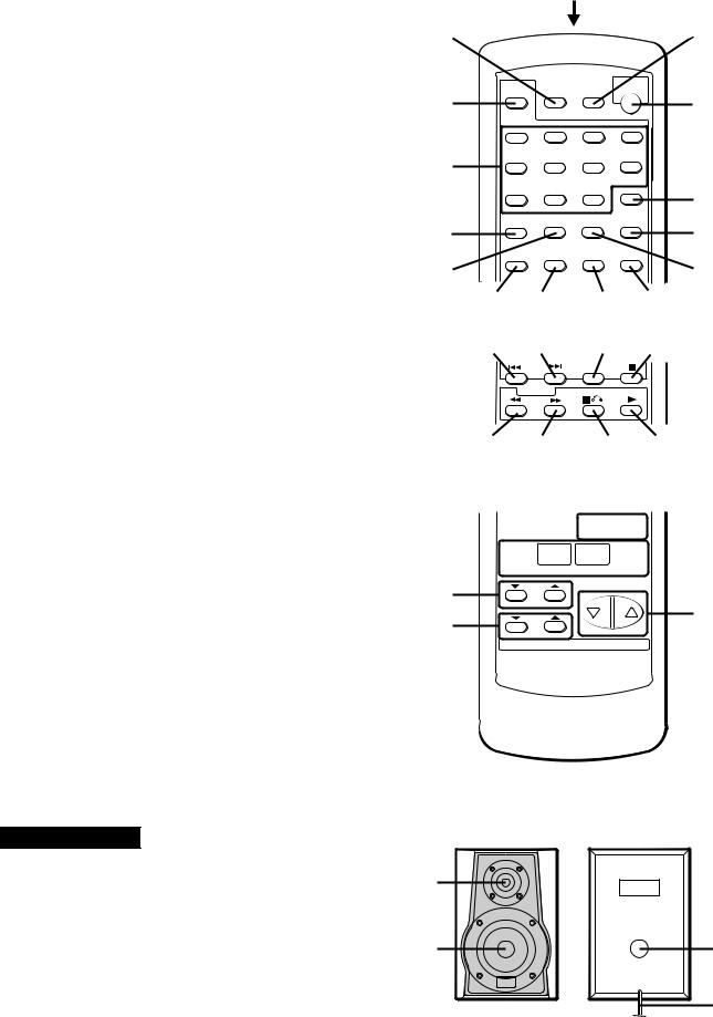
■Remote control
1.Remote Control Transmitter LED
2.Timer Button
3.(VCD/CD) Audio Mode Button
4.(VCD/CD) Direct Search Buttons
5.(VCD/CD) Display Button
6.(VCD) Video Intro Button
7.Sleep Button
8.On/Stand-by Button
9.(VCD) TV Type Button
10.(VCD) Track Digest Button
11.(VCD) Time Search Button
12.(VCD/CD) Memory Button
13.(VCD/CD) Clear Button
14.(VCD/CD) Random Button
15.(VCD) Playback Control Auto/Off Button
16.(VCD) Skip/Previous Button (CD) Track Down Button
17.(VCD) Skip/Next Button (CD) Track Up Button
18.(VCD/CD) Repeat Button
19.(VCD/CD) Pause Button
20.(VCD/CD) Review Button (TAPE) Rewind Button
21.(VCD/CD) Cue Button (TAPE) Fast Forward Button
22.(VCD) Stop/Return Button (CD/TAPE) Stop Button
23.(VCD/CD/TAPE) Play Button
24.(TAPE) Record Pause Button
25.Surround Button
26.Function Buttons
27.Treble Buttons
28.Bass Buttons
29.(TUNER) Preset Up/Down Buttons
30.Volume Up/Down Buttons
CP-XL70U
1.Tweeter
2.Woofer
3.Bass Reflex Duct
4.Speaker Wire
XL-70V
|
|
1 |
|
2 |
|
|
7 |
3 |
|
|
8 |
4 |
|
|
|
|
|
|
9 |
5 |
|
|
10 |
6 |
|
|
11 |
12 |
13 |
14 |
15 |
16 |
17 |
18 |
19 |
20 |
21 |
22 |
23 |
24 |
25 |
|
|


 29 26
29 26 


27
30
28
1
2 |
3 |
4
– 5 –
– 6 –
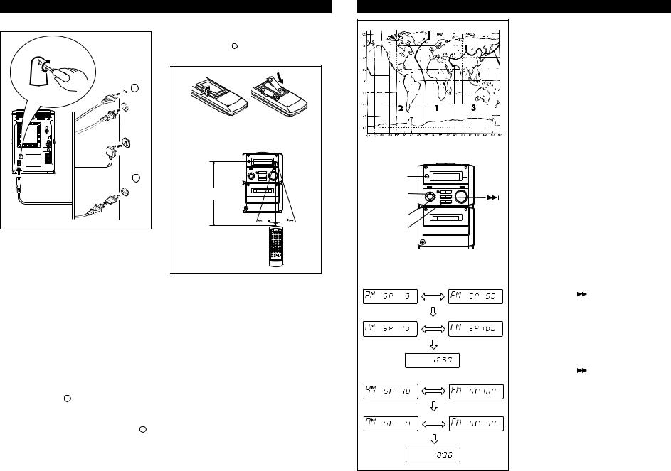
PREPARATION FOR USE
■ Connecting the AC power lead
RATED
LINE VOLTAGE
230V
ı
240V

 1
1
2
To an AC socket.
Check the setting of the AC voltage selector located on the rear panel before plugging the unit into an AC socket. If necessary, adjust the selector to correspond to the AC power voltage used in your area.
Selector adjustment:
Turn the selector with a screwdriver until the appropriate voltage number appears in the window (110/127/220/230 - 240V AC).
Notes:
●Unplug the AC power lead from the AC socket if the unit is not to be used for a prolonged period of time.
●Never use a power lead other than the one supplied.
Otherwise, a malfunction or an accident may occur.
●AC Plug Adaptor
In areas (or countries) where an AC socket as shown in illustration 2 is used, connect the unit using the AC plug adaptor supplied with the unit, as illustrated. The AC plug adaptor is not included in areas where the AC wall socket and AC power plug can be directly connected (see illustration 1 ).
■Remote control
●When inserting or removing the batteries, push them towards the - battery terminals.
●Installing the batteries incorrectly may cause the unit to malfunction.
● 2 “AA” size batteries (UM/SUM-3, R6, HP-7 |
|
or similar) |
|
0.2m - 6m |
|
(8"- 20') |
|
15 |
15 |
|
|
Precautions for battery use:
●Insert the batteries according to the direction indicated in the battery compartment.
●Replace all old batteries with new ones at the same time.
●Do not mix old and new batteries.
●Remove the batteries if they are weak or if the unit will not be used for long periods of time. This will prevent potential damage due to battery leakage.
Caution:
Do not use rechargeable batteries (nickel-cadmium battery, etc.).
Notes concerning use:
●Replace the batteries if the operating distance is reduced or if the operation becomes erratic.
●Periodically clean the transmitter LED on the remote control and the sensor on the main unit with a soft cloth.
●Exposing the sensor on the main unit to strong light may interfere with operation. Change the lighting or the direction of the unit.
●Keep the remote control away from moisture, excessive heat, shock, and vibrations.
(Continued) |
|
|
|
-XL |
|
|
■ AM/FM interval (span) |
70V |
|
|
|
|
||
|
|
The International Telecommunication Union (ITU) |
|
|
|
|
has established that member countries should |
|
|
|
|
maintain either a 10 kHz or a 9 kHz interval be- |
|
|
|
|
tween broadcasting frequencies of any AM station. |
|
|
|
|
The illustration shows the 9 kHz interval zones (re- |
|
|
|
|
gions 1 and 3), and the 10 kHz interval zone (re- |
|
|
|
|
gion 2). |
|
|
|
|
This product is not equipped with a span selector. |
|
|
|
|
However, it will be adjusted to 9 kHz AM interval |
|
|
|
|
(50 kHz FM interval) when shipped from the fac- |
|
|
|
|
tory. |
|
|
|
|
Before using the unit, be sure to set it for the AM |
|
|
|
|
tuning interval (span) used in your area. |
|
|
|
|
To check the tuning span currently selected: |
|
|
ON/ |
|
1 Press the ON/STAND-BY button to turn the |
OPERATION |
|
|
power on. |
|
||
STAND-BY |
|
|
||
|
2 Press the FUNCTION button until “FM” or |
|||
|
|
|||
|
|
|
||
MEMORY/ |
|
“AM” appears in the display. |
|
|
|
3 Press the BAND button to select the AM |
|
||
SET |
|
|
||
BAND |
|
band. |
|
|
|
● If “AM 531 kHz” is displayed, it means that the |
|
||
|
|
|
||
FUNCTION |
|
radio has been adjusted for a 9 kHz span. If “AM |
|
|
|
|
530 kHz” is displayed, it means that the radio |
|
|
|
|
has been adjusted for a 10 kHz span. |
MANUAL |
|
|
|
To change from a 9 kHz AM (50 kHz FM) interval |
||
|
|
|
||
|
|
to a 10 kHz AM (100 kHz FM) interval: |
|
|
|
|
1 Press the ON/STAND-BY button to enter the |
|
|
|
|
stand-by mode. |
|
|
kHz |
kHz |
2 Hold down the |
button and the MEMORY/ |
|
|
|
SET button for at least 4 seconds. Release |
|
|
|
|
the buttons when “AM SP 10 kHz” and “FM |
|
|
|
|
SP 100 kHz” are displayed alternately. |
|
|
kHz |
kHz |
● The unit will return to the clock display. |
|
|
|
|
To return to a 9 kHz AM (50 kHz FM) interval: |
|
|
|
|
1 Press the ON/STAND-BY button to enter the |
|
|
|
|
stand-by mode. |
|
|
|
|
2 Hold down the |
button and the MEMORY/ |
|
|
|
SET button for at least 4 seconds. Release |
|
|
kHz |
kHz |
the buttons when “AM SP 9 kHz” and “FM |
|
|
SP 50 kHz” are displayed alternately. |
|
|||
|
|
|
||
|
|
● The unit will return to the clock display. |
|
|
|
|
Caution: |
|
|
kHz |
kHz |
● When the unit is left for a few hours after the |
|
|
|
|
|
||
|
|
span has been switched and AC power lead dis- |
|
|
|
|
connected, it will be automatically returned to a |
|
|
|
|
9 kHz span. If this happens, set the span again. |
|
|
|
|
● When the span is switched, any stations that are |
|
|
|
|
memorised will be cancelled. |
|
|
– 7 –
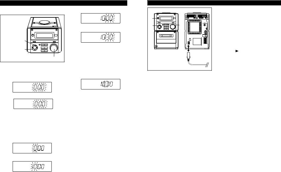
SETTING THE CLOCK
In this example, the clock is set for the 24-hour (0:00) system.
MEMORY/SET
CLOCK/TIMER/ SLEEP
Jog dial
(Main unit operation)
1 Press the CLOCK/TIMER/SLEEP button.
2 Within 3 seconds, press the MEMORY/SET button.
3 Turn the jog dial to select the time display mode.
0:00 
 AM 12:00
“0:00” → The 24-hour display will appear. (0:00 - 23:59)
“AM 12:00” → The 12-hour display will appear. (AM 12:00 - PM 11:59)
●Note that this can only be set when the unit is first installed or it has been reset.
4 Press the MEMORY/SET button.
5 Adjust the hour by turning the jog dial.
●When the jog dial is turned one click clockwise, the time will increase by 1 hour. When it is turned one click anti-clockwise, the time will decrease by 1 hour.
Keep turning the jog dial to change the time continuously.
●When the 12-hour display is selected, “AM” will change automatically to “PM”.
6 Press the MEMORY/SET button.
7 Adjust the minutes by turning the jog dial.
●When the jog dial is turned one click clockwise, the time will increase by 1 minute. When it is turned one click anti-clockwise, the time will decrease by 1 minute.
Keep turning the jog dial to change the time continuously.
●The hour setting will not advance even if minutes advance from “59” to “00”.
8 Press the MEMORY/SET button.
●The clock starts operating from “0” seconds. (Seconds are not displayed.)
Note:
●The clock display will flash on and off when the AC power supply is restored after a power failure occurs or after the AC power lead is disconnected.
If this happens, follow the procedure below to change the clock time.
To change the clock time:
Perform steps 1, 2 and 5 - 8 above.
To change the time display mode:
Perform steps 1 - 3 in the section “RESETTING THE MICROCOMPUTER”.
Perform steps 1 - 8 above.
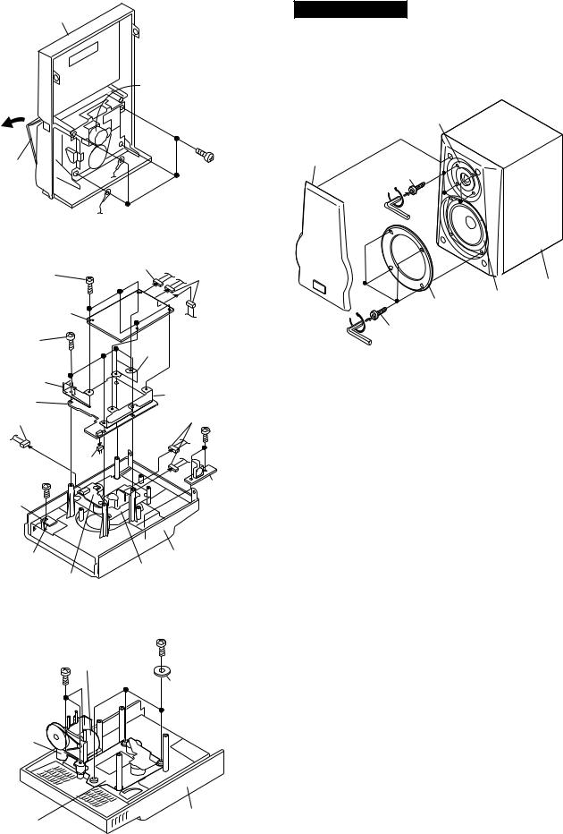
RESETTING THE MICROCOMPUTER
1 |
|
3 |
3 |
|
AC INPUT |
|
2,3 |
Reset the microcomputer under the following conditions:
●To erase all of the stored memory contents (clock and timer settings, and tuner and CD presets).
●If the display is not correct.
●If the operation is not correct.
1 Press the ON/STAND-BY button to enter the stand-by mode.
2 Unplug the AC power lead from the AC INPUT socket on this unit.
3 Whilst pressing down the MEMORY/SET button and the button, plug the AC power lead into the AC INPUT socket on this unit.
Caution:
●The operation explained above will erase all data stored in memory, such as clock and timer settings, and tuner and CD presets.
70V-XL

XL-70V
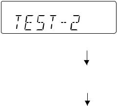
DISASSEMBLY
Caution on Disassembly
Follow the below-mentioned notes when disassembling the unit and reassembling it, to keep it safe and ensure excellent performance:
1.Take cassette tape and compact disc out of the unit.
2.Be sure to remove the power supply plug from the wall outlet before starting to disassemble the unit.
3.Take off nylon bands or wire holders where they need to be removed when disassembling the unit. After servicing the unit, be sure to rearrange the leads where they were before disassembling.
4.Take sufficient care on static electricity of integrated circuits and other circuits when servicing.
XL-70V |
(A1)x1 |
|
Top Cabinet |
||
ø3x10mm |
||
|
CD PWB
 (B2)x1
(A1)x1
ø3x10mm
|
|
Main PWB |
|
Display |
(B2)x1 |
(B1)x1 |
|
PWB |
|||
(B2)x2 |
ø3x10mm |
||
|
|||
Front |
|
(C1)x2 |
|
Panel |
|
||
(B2)x1 |
|
ø3x10mm |
|
|
|
XL-70V
STEP |
REMOVAL |
|
PROCEDURE |
FIGURE |
|
|
|
|
|
|
|
1 |
Side Panel(Left/Right) |
1. |
Screw .................. |
(A1) x8 |
8-1 |
|
|
|
|
|
|
2 |
Top Cabinet |
1. |
Screw .................. |
(B1) x1 |
8-1 |
|
|
2. |
Socket ................. |
(B2) x5 |
|
|
|
|
|
|
|
3 |
Rear Panel |
1. |
Screw .................. |
(C1) x3 |
8-1 |
|
|
2. |
Screw .................. |
(C2) x2 |
|
|
|
|
|
|
|
4 |
Power Amp. PWB |
1. |
Screw .................. |
(D1) x1 |
8-2 |
|
|
2. |
Socket ................. |
(D2) x2 |
|
|
|
|
|
|
|
5 |
Main PWB/ |
1. |
Screw .................. |
(E1) x4 |
8-3 |
|
Headphones PWB |
2. Screw .................. |
(E2) x1 |
|
|
|
|
3. |
Bracket ................ |
(E3) x1 |
|
|
|
4. |
Socket ................. |
(E4) x3 |
|
|
|
5. |
Flat wire............... |
(E5) x1 |
|
|
|
6. |
Socket ................. |
(E6) x1 |
|
|
|
|
|
|
|
6 |
Jog Switch PWB |
1. |
Socket ................. |
(F1) x1 |
8-3 |
|
|
2. |
Screw .................. |
(F2) x2 |
|
|
|
|
|
|
|
7 |
Display PWB/ |
1. |
Screw .................. |
(G1) x3 |
8-3 |
|
LED PWB |
2. |
Screw .................. |
(G2) x3 |
|
|
(With Jog Motor |
3. |
Bracket ................ |
(G3) x1 |
|
|
Holder) |
4. |
Socket ................. |
(G4) x1 |
|
|
|
5. |
Knob .................... |
(G5) x1 |
|
|
|
6. |
Hook .................... |
(G6) x2 |
|
|
|
7. |
Hook .................... |
(G7) x2 |
|
|
|
|
|
|
|
8 |
Front Panel |
1. |
Screw .................. |
(H1) x1 |
8-3 |
|
|
2. |
Socket ................. |
(H2) x1 |
|
|
|
3. |
Screw .................. |
(H3) x1 |
|
|
|
|
|
|
|
9 |
Power PWB |
1. |
Screw .................. |
(J1) x4 |
8-3 |
|
|
2. |
Screw .................. |
(J2) x1 |
|
|
|
3. |
Screw .................. |
(J3) x1 |
|
|
|
4. |
Bracket ................ |
(J4) x1 |
|
|
|
|
|
|
|
10 |
Tape Mechanism |
1. |
Open the cassette holder. |
9-1 |
|
|
|
2. |
Screw .................. |
(K1) x4 |
|
|
|
|
|
|
|
11 |
Video PWB |
1. |
Screw .................. |
(L1) x4 |
9-2 |
|
|
2. |
Socket ................. |
(L2) x3 |
|
|
|
|
|
|
|
12 |
CD PWB/ |
1. |
Screw .................. |
(M1) x7 |
9-2 |
|
Open Close Switch |
2. |
Bracket ................ |
(M2) x3 |
|
|
PWB/CD Lid PWB |
3. |
Socket ................. |
(M3) x4 |
|
|
(Note) |
4. |
Hook .................... |
(M4) x1 |
|
|
|
|
|
|
|
13 |
CD Mechanism |
1. |
Screw .................. |
(N1) x3 |
9-3 |
|
|
2. |
Screw .................. |
(N2) x3 |
|
|
|
|
|
|
|
Note:
After removing the connector for the optical pickup from the connector, wrap the conductive aluminium foil around the front end of connector remove to protect the optical pickup from electrostatic damage.
(C2)x2 |
(A1)x4 |
ø3x8mm |
ø3x10mm |
Power |
Side Panel |
PWB |
(Left) |
|
|
|
(C1)x1 |
(A1)x2 |
Rear Panel ø3x10mm |
ø3x10mm |
Side Panel (Right) |
|
|
|
Figure 8-1 |
(D1)x1 |
Main PWB |
ø3x8mm |
|
(D2)x2 |
|
Power Amp. |
Power |
PWB |
PWB |
Figure 8-2
|
|
(G2)x2 |
|
(E6)x1 |
|
(E4)x1 |
ø2.5x10mm |
|
|
(F1)x1 |
|
|
|
|
|
(G7)x2 |
(G6)x2 |
|
(E1)x1 |
LED PWB |
|
|
ø3x8mm |
|
|
|
|
||
(G5)x1 |
|
|
|
Headphones |
|
|
(G3)x1 |
PWB |
|
Display PWB |
|
|
|
(E1)x1 |
|
|
(E4)x1 |
(H2)x1 ø3x8mm |
|
|
|
|
||
Front Panel |
|
|
(E5)x1 |
(E1)x2 |
|
|
|
|
|
Jog Switch |
|
|
|
ø3x10mm |
PWB |
|
|
|
|
(F2)x2 |
|
|
|
Main PWB |
|
|
|
(G2)x1 |
|
ø2.5x12mm |
|
|
|
|
Jog Motor |
|
|
|
ø2.5x10mm |
Tape Holder |
|
|
|
|
Mechanism |
|
|
|
(E3)x1 |
PWB |
|
|
|
|
|
|
|
|
|
(G4)x1 |
|
|
|
(G1)x3 |
|
|
|
|
|
(H3)x1 |
|
|
|
ø2.5x14mm |
|
|
|
|
|
ø3x6mm |
Power |
|
|
(E2)x1 |
(E4)x1 |
PWB |
|
|
|
|
|
ø3x8mm |
||
|
|
(H1)x1 |
|
|
(J3)x1 |
|
(J2)x1 |
(J1)x4 |
|
|
ø3x8mm |
ø4x6mm |
||
ø3x6mm |
|
|
ø3x10mm |
|
Power PWB |
(J4)x1 |
|
|
|
Sub Power |
|
|
|
|
Transformer |
|
|
|
|
Figure 8-3
– 8 –
Front Panel
Tape
Mechanism
Open
Cassette |
|
(K1)x4 |
|
Holder |
|
||
|
ø2.5x10mm |
||
|
|
||
|
Figure 9-1 |
|
|
(L1)x4 |
(L2)x1 |
|
|
|
(L2)x2 |
||
ø2x10mm |
|
||
|
|
||
Video PWB |
|
|
|
(M1)x4 |
(M2)x1 |
|
|
ø2.5x14mm |
|
||
(M2)x1 |
|
(M2)x1 |
|
CD PWB |
|
||
|
|
||
(M3)x1 |
|
(M3)x2 |
|
|
(M1)x2 |
||
|
|
||
|
|
ø2.5x8mm |
|
(M1)x1 |
(M3)x1 |
|
|
ø2.5x10mm |
|
|
|
|
|
CD Lid |
|
(M4)x1 |
|
PWB |
|
Open/Close |
|
Top Cabinet |
|
|
|
||
Switch PWB |
CD Mechanism |
||
CD Motor PWB |
|
||
|
Figure 9-2 |
|
|
|
CD Lid |
(N2)x3 |
|
|
ø2.5x10mm |
||
(N1)x3 |
Motor |
||
|
|||
|
|
||
ø2.5x10mm |
|
PWB |
|
|
|
||
|
|
Washer x3 |
|
CD Lid
Motor
Holder
Top Cabinet
CD Mechanism
Figure 9-3
XL-70V
CP-XL70U
STEP |
REMOVAL |
|
PROCEDURE |
FIGURE |
|
|
|
|
|
|
|
1 |
Woofer/Tweeter |
1. Net Frame ........... |
(A1) x1 |
9-4 |
|
|
|
2. |
Screw .................. |
(A2) x4 |
|
|
|
3. |
Woofer Ring ........ |
(A3) x1 |
|
|
|
4. |
Screw .................. |
(A4) x4 |
|
|
|
|
|
|
|
Tweeter
(A1)x1 (A4)x4 ø3x12mm
Speaker Box
(A3)x1 Woofer
(A2)x4
ø4x20mm
Figure 9-4
– 9 –
XL-70V
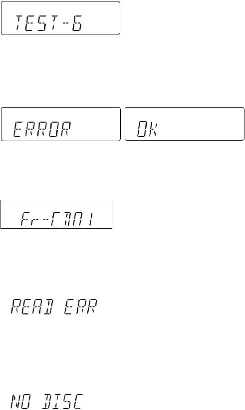
TEST MODE
The test mode applied to this microcomputer has three modes, namely ordinary test mode to be used for adjustment or measurement, aging test mode to be used for aging test, and self-diagnosis test mode for self-inspection in case of final product inspection.
1.Turning on the test mode
To turn on the specific test mode, press the POWER button, holding down the following two buttons in the ordinary stand-by mode (power off state). In this case only the main unit button is valid. Even when the POWER of remote control button is set to on, the test mode is not turned on.
[Ordinary test mode] |
|
|
1. |
Tuner Test Mode (TEST 2) ............................... |
Volume/JOG Dial Selector + Volume Select |
2. |
Electronic volume Test Mode (TEST 3) ........... |
REW/REV + FF/FWD |
3. |
Timer Test Mode (TEST 4) ............................... |
FUNCTION + Volume Select |
4. LCD Test Mode (TEST 5) ................................. |
FUNCTION + FF/FWD |
|
[Self-diagnosis test mode]
1.Button input diagnosis test mode (TEST 6)...... REW/REV + Volume Select
2.Tuner Test Mode (TEST 2)
1.Outline of tuner (radio) test mode
The tuner test mode is intended to store the adjustment and measurement frequencies in the preset memory CH without frequency setting by adjusting personnel when the tuner section is adjusted in the production line.
2.Details of tuner test mode
When the power is turned on by using the "POWER" button while the "Volume/JOG Dial Selector" and "Volume Select" buttons are held down in POWER OFF state, the frequency for adjustment and measurement of destination specified by the AREA terminal is preset and stored in the preset memory CH. However, Ordinary 1 and Ordinary 2 are set to the designation (destination selected by SPAN switching operation) set when the test mode is set. (As for frequencies to be preset and stored for each destination, refer to item 3.)
The tuner test mode is started from preset No.1.
The operations of test mode are identical with the ordinary operations of TUNER function. However, FUNCTION switching is invalid.
Since it is necessary to discard the content of preset memory when the tuner test mode is ended, "0000" or "1111" bits are written in the memory to be checked in case of memory check (in case of initial setting) so that memory abnormality is detected in case of initial setting so as to ensure memory initialization.
When the tuner test mode is turned on, the following indication lights for one second.
• The TUNER TEST 2 mode is set as a result of Volume Select + POWER. -> IF AC is set to OFF in the TEST 2 mode, the initial state is restored.
When POWER is set to OFF, the memory of TEST 2 mode is protected.
When the power is turned on again, the ordinary operation is enabled while the data is stored in the memory (besides TUNER).
If AC OFF state is maintained in this state for about 1/2 day, start is executed in the initial state.
• To clear the whole memory, insert the AC cord, holding down MEMORY + PLAY.
– 10 –
XL-70V
3. Preset frequencies for various destinations (random preset memory)
CH |
BAND |
Ordinary 1, China |
|
|
|
1 |
|
FM 87.50 MHz |
2 |
|
FM108.00 MHz |
3 |
FM STEREO |
FM 98.00 MHz |
4 |
|
FM 90.00 MHz |
5 |
|
FM106.00 MHz |
|
|
|
6 |
|
AM 531 kHz |
7 |
|
AM1602 kHz |
8 |
AM |
AM 990 kHz |
9 |
|
AM 603 kHz |
10 |
|
AM1404 kHz |
|
|
|
11 |
|
|
12 |
|
|
13 |
LW |
|
14 |
|
|
15 |
|
|
|
|
|
CH |
BAND |
Ordinary 1, China |
|
|
|
16 |
|
|
17 |
|
|
18 |
|
|
19 |
|
|
20 |
|
|
|
|
|
21 |
|
|
22 |
|
|
23 |
|
|
24 |
|
|
25 |
|
|
|
|
|
26 |
|
FM106.00 MHz |
27 |
|
FM 90.00 MHz |
28 |
FM MONO |
FM 98.00 MHz |
29 |
|
FM108.00 MHz |
30 |
|
FM 87.50 MHz |
|
|
|
• The hatched sections of the table are not stored in memory.
3.Electronic volume Test Mode (TEST 3)
When the test mode is set, the following indication lights for one second.
When this mode is set, BASS/TREBLE is set to 0 (0 dB) and SURROUND mode is set to off, and start-up function is set to CD when volume is -14 dB (STEP 17). The button operations in the test mode are the same as those of ordinary operation excepting sound volume UP/DOWN.
(1)The indication is the same as that of ordinary operation excepting test mode setting.
(2)The sound volume control with the sound volume UP/DOWN button is only the following 3 steps unlike the ordinary state.
Volume- ∞ (STEP 0) <-> Volume-14 dB (STEP 23) <-> Volume-0 (STEP 30)
(3)BASS/TREBLE and SURROUND are switched when button operation is performed.
4.Timer test Mode (TEST 4)
When the test mode is set, the following indication lights for one second.
The current time and timer time are set in the following procedure to perform the timer playback.
1.Set the current time to 1:00, set the timer to ON time 1:02, set the function to Tape, and set volume STEP 8. One minute is counted as one second, and the timer playback operation is performed. The fade-in (when playback is started) is executed at a rate of one step for 0.5 sec. After completion of fade-in the fade-out is executed at a rate of one step for 0.5 sec (WAIT 1 sec inserted). After completion of fade-out the power is turned off (after WAIT 1 sec), and the mode is changed to the standby mode.
The indication during operation is the same as that of ordinary timer operation.
5.LCD Test Mode (TEST 5)
When the LCD test mode is set, all the LCD segments are lighted. After that the indication is changed as follows according to the "PLAY" button input.

 Lighting of all segments
  Lighting of odd segments
  Lighting of even segments
– 11 –
XL-70V
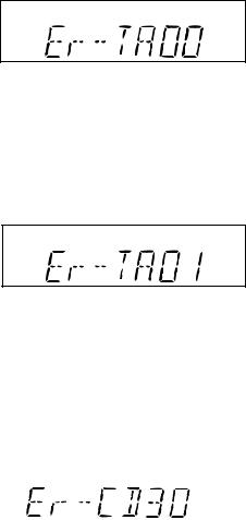
6.Button input diagnosis Test Mode (TEST 6)
When the test mode is set, the following indication appears.
This test mode is intended to check whether all the main unit buttons can be detected. Accordingly, in this test mode checking as to whether the "POWER" button was pressed after all the buttons shown below were pressed is performed. If the result is OK, is indicated. Even any one of keys was not pressed, an error is indicated. In case of OK termination or error termination exit from this mode occurs when the "POWER" button is pressed next time, and the stand-by mode is set.
1.In case of "Review" + "Volume/Jog Dial Select Button"
The following 14 buttons are detected as all buttons.
The OK/NG indication of test result is as follows.
ERROR LIST
PU-IN SW detection error display
Error contents ............................ |
Displayed when the ON of detection SW could not be detected even after a certain period of time |
||
|
|
passed, even though controlled to return the CD pickup to the most inside periphery in |
|
|
|
microcomputer. |
|
Major causes ............................. |
Failure of PU-IN SW or connection failure, and failure of slide motor or connection failure |
||
Recovery method from error ..... |
Remove the cause of the error and turn on the power again. |
||
CD Read error display |
|
|
|
|
|
|
|
|
|
|
|
Error contents ............................ |
Displayed when the data of the DISC can not be read correctly, or can be read however the |
||
|
|
standard of the disc is impossible to be played back. |
|
Major cause ............................... |
The disc is back to front. Other disc than CD-DA/VCD1.1/VCD2.0 is inserted. |
||
|
|
The flaw or contamination of the disc is great and the data cannot be read. |
|
Recovery method from error ..... |
Open the CD cover and insert a correct disc correctly. Remove the contamination or flaw of the |
||
|
|
disc. |
|
NO DICS display |
|
|
|
|
|
|
|
|
|
|
|
Error contents ............................ |
Displayed when impossible to focus on the disc. |
Major cause ............................... |
The disc is back to front. Other disc than CD-DA/VCD1.1/VCD2.0 is inserted. The flaw or |
|
contamination of the disc is great and the data cannot be read. |
Recovery method from error ..... |
Open the CD cover and insert a correct disc correctly. Remove the contamination or flaw of the |
|
disc. |
– 12 –
XL-70V
TAPE mechanism error display (1)
Error contents ............................ |
Displayed when not becomes "ON" while the mechanism operating detection SW "CAM-SW" is |
|
being operated even though the motor or solenoid are controlled to operate the tape for playback/ |
|
FF/REW/Recording. |
Major cause ............................... |
When displayed even though the mechanism is working, failure of CAM-SW and connection |
|
failure. |
|
When the mechanism is not working, failure of the motor and solenoid and connection failure. |
Recovery method from error ..... |
Remove the cause of the error and turn on the power again. |
TAPE mechanism error display (2)
Error contents ............................ |
Displayed when the initialization cannot be completed, even though the microcomputer controls |
||
|
|
the motor or the solenoid to initialize the tape mechanism (set the mechanism to the stop |
|
|
|
condition.) (Mechanism operating detection SW "CAM-SW" is stopped and does not become |
|
|
|
"OFF".) |
|
Major cause ............................... |
When displayed even though the mechanism is working, failure of CAM-SW and connection |
||
|
|
failure. |
|
|
|
When the mechanism is not working, failure of the motor and solenoid and connection failure. |
|
Recovery method from error ..... |
Remove the cause of the error and turn on the power again. |
||
VCD unit communication error |
|
|
|
|
|
|
|
|
|
|
|
Error contents ............................ |
The system computer cannot communicate with VCD unit microcomputer. Or can communicate |
|
however the contents are not as specified in the specification. |
Major cause ............................... |
VCD microcomputer or the CD servo microcomputer are in abnormal operation. |
|
The power is not supplied to the VCD unit and CD servo unit. |
|
The communication line between the system microcomputer and the VCD unit are short-circuit |
|
or open. |
Recovery method from error ..... |
Remove the cause of the error and turn on the power again. |
– 13 –
XL-70V
NOTES ON SCHEMATIC DIAGRAM
∙Resistor:
To differentiate the units of resistors, such symbol as K and M are used: the symbol K means 1000 ohm and the symbol M means 1000 kohm and the resistor without any symbol is ohm-type resistor. Besides, the one with “Fusible” is a fuse type.
∙Capacitor:
To indicate the unit of capacitor, a symbol P is used: this symbol P means pico-farad and the unit of the capacitor without such a symbol is microfarad. As to electrolytic capacitor, the expression “capacitance/withstand voltage” is used.
(CH), (TH), (RH), (UJ): Temperature compensation (ML): Mylar type
(P.P.): Polypropylene type
∙Schematic diagram and Wiring Side of P.W.Board for this model are subject to change for improvement without prior notice.
∙The indicated voltage in each section is the one measured by Digital Multimeter between such a section and the chassis with no signal given.
1.In the tuner section, ( ) indicates AM
< > indicates FM stereo
2.In the main section, a tape is being played back.
3.In the deck section, a tape is being played back. ( ) indicates the record state.
4.In the power section, a tape is being played back.
5.In the CD section, the CD is stopped.
∙Parts marked with “  ” (
” ( 


 ) are important for maintaining the safety of the set. Be sure to replace these parts with specified ones for maintaining the safety and performance of the set.
REF. NO |
DESCRIPTION |
POSITION |
|
|
|
NSW801 |
PICKUP IN |
ON—OFF |
|
|
|
SW651 |
VOLTAGE SELECTOR |
230-240V |
SW700 |
JOG |
ON—OFF |
|
|
|
SW709 |
ON/STAND-BY |
ON—OFF |
|
|
|
SW710 |
CLOCK/TIMER/SLEEP |
ON—OFF |
|
|
|
SW711 |
TUNING UP |
ON—OFF |
|
|
|
SW712 |
PLAY/CD PAUSE |
ON—OFF |
|
|
|
SW713 |
VOLUME SELECT |
ON—OFF |
|
|
|
SW718 |
SURROUND |
ON—OFF |
|
|
|
SW721 |
MEMORY/SET |
ON—OFF |
|
|
|
SW722 |
BASS/TREBLE |
ON—OFF |
|
|
|
REF. NO |
DESCRIPTION |
POSITION |
|
|
|
SW723 |
BAND |
ON—OFF |
|
|
|
SW724 |
REC. PAUSE |
ON—OFF |
|
|
|
SW725 |
STOP/CLEAR |
ON—OFF |
|
|
|
SW726 |
TUNING DOWN |
ON—OFF |
|
|
|
SW727 |
FUNCTION |
ON—OFF |
|
|
|
SW728 |
VOLUME JOG |
ON—OFF |
|
|
|
SW730 |
CD LID OPEN/CLOSE |
ON—OFF |
|
|
|
SW802 |
CD LID |
ON—OFF |
|
|
|
SW901 |
FOOL PROOF |
ON—OFF |
|
|
|
SW902 |
CAM |
ON—OFF |
|
|
|
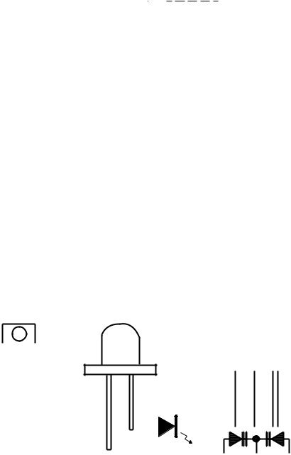
TYPES OF TRANSISTOR AND LED
|
FRONT |
|
2SA933 SR |
|
|
|
|
|
|
|
|
|
|
|
|
|
|
|
|
|
|
|
|
|||||||
|
|
2SB562 C |
|
|
|
|
|
|
|
|
|
|
|
|
|
|
|
|
|
|
|
|
||||||||
|
|
|
|
|
|
|
|
|
|
|
|
|
|
|
|
|
|
|
|
|
|
|||||||||
|
|
VIEW |
|
2SC2001 K |
|
FRONT |
|
|
|
|
|
|
|
|
|
|
|
|
||||||||||||
|
|
|
|
|
|
|
|
|
2SC535 C |
|
|
VIEW |
|
|
|
|
|
|
|
|
|
|
|
|
||||||
|
|
|
|
|
|
|
|
|
|
|
|
|
|
|
|
|
|
|
|
|
|
|
||||||||
|
|
|
|
|
|
|
|
|
2SD1858 R |
|
|
|
|
FRONT |
|
|
|
|
|
|
|
|
|
|||||||
|
|
|
|
|
|
|
|
|
|
|
|
|
|
|
|
|
|
|
|
|
|
|
|
|
|
|
|
|||
|
|
|
|
|
|
|
|
|
2SK246 GR |
|
|
|
|
|
|
|
|
|
|
|
|
|
|
|
|
|
|
|
||
|
|
|
|
|
|
|
|
|
|
|
|
|
|
|
|
|
|
|
VIEW |
|
|
|
|
|
|
|
|
|
||
|
|
|
|
|
|
|
|
|
KRA102 M |
|
|
|
|
|
|
|
|
|
|
|
|
|
|
|
|
|
|
|
|
|
|
E C B |
KRC102 M |
|
|
|
|
|
|
|
|
|
|
|
|
|
|
|
|
|
|
|
|
||||||||
|
|
|
|
|
|
|
|
|
|
|
|
|
|
|
|
|
|
|
|
|
||||||||||
(S) (G)(D) |
KRC104 M |
|
|
|
|
|
|
|
|
|
|
|
|
|
|
|
|
|
|
|
|
|||||||||
|
B C E |
|
|
|
|
|
|
|
|
|
|
|
||||||||||||||||||
(1) (2) (3) |
KRC107 M |
|
|
|
|
|
|
|
|
|
|
|
|
|||||||||||||||||
2SD2012 Y |
MPG3372X |
1 2 3 |
||||||||||||||||||||||||||||
|
|
|
|
|
|
|
|
|
KTA1266 GR |
|||||||||||||||||||||
|
|
|
|
|
|
|
|
|
KTC3199 GR |
|
|
|
|
|
|
|
|
|
HY2043 |
|
SVC348S |
|||||||||
|
|
|
|
|
|
|
|
|
|
|
|
|
|
|
|
|
|
|
|
|
||||||||||
KDV147B
– 14 –
XL-70V
VOLTAGE
|
|
|
IC701 |
|
|
|
IC802 |
|
|
IC806 |
|
|
IC14V |
|
|
|
IC15V |
|
|||||||
|
PIN |
|
VOLTAGE |
|
PIN |
VOLTAGE |
|
PIN |
VOLTAGE |
|
PIN |
VOLTAGE |
|
PIN |
VOLTAGE |
|
PIN |
VOLTAGE |
|
PIN |
VOLTAGE |
|
PIN |
VOLTAGE |
|
|
NO. |
|
|
NO. |
|
NO. |
|
NO. |
|
NO. |
|
NO. |
|
NO. |
|
NO. |
|||||||||
|
1 |
|
2.5V |
|
51 |
— |
|
1 |
2.6V |
|
1 |
2.5V |
|
1 |
0V |
|
51 |
0V |
|
1 |
3.6V |
|
51 |
3.6V |
|
|
2 |
|
2.5V |
|
52 |
4.8V |
|
2 |
2.5V |
|
2 |
2.5V |
|
2 |
— |
|
52 |
1.3V |
|
2 |
3.5V |
|
52 |
2.7V |
|
|
3 |
|
2.5V |
|
53 |
4.8V |
|
3 |
0V |
|
3 |
2.7V |
|
3 |
— |
|
53 |
— |
|
3 |
3.5V |
|
53 |
3.5V |
|
|
4 |
|
2.5V |
|
54 |
4.8V |
|
4 |
2.6V |
|
4 |
3.1V |
|
4 |
— |
|
54 |
5V |
|
4 |
1.8V |
|
54 |
3.3V |
|
|
5 |
|
0V |
|
55 |
4.8V |
|
5 |
5V |
|
5 |
3.8V |
|
5 |
5V |
|
55 |
2.3V |
|
5 |
1.7V |
|
55 |
1.2V |
|
|
6 |
|
1.7V |
|
56 |
5V |
|
6 |
3.3V |
|
6 |
2.9V |
|
6 |
3.5V |
|
56 |
0V |
|
6 |
1.8V |
|
56 |
1.3V |
|
|
7 |
|
3.3V |
|
57 |
5V |
|
7 |
0V |
|
7 |
— |
|
7 |
0V |
|
57 |
0V |
|
7 |
1.4V |
|
57 |
1.6V |
|
|
8 |
|
5V |
|
58 |
5V |
|
8 |
0V |
|
8 |
— |
|
8 |
1.2V |
|
58 |
0V |
|
8 |
1.8V |
|
58 |
1.4V |
|
|
9 |
|
2.5V |
|
59 |
— |
|
9 |
— |
|
9 |
5V |
|
9 |
0V |
|
59 |
5V |
|
9 |
1.8V |
|
59 |
1.4V |
|
|
10 |
|
2.5V |
|
60 |
5V |
|
10 |
— |
|
10 |
— |
|
10 |
3.5V |
|
60 |
5V |
|
10 |
1.7V |
|
60 |
1.4V |
|
|
11 |
|
0V |
|
61 |
0V |
|
11 |
— |
|
11 |
— |
|
11 |
0V |
|
61 |
0V |
|
11 |
1.8V |
|
61 |
1.5V |
|
|
12 |
|
2.3V |
|
62 |
0V |
|
12 |
— |
|
12 |
5V |
|
12 |
2.7V |
|
62 |
0V |
|
12 |
1.8V |
|
62 |
1.2V |
|
|
13 |
|
2.4V |
|
63 |
0V |
|
13 |
5V |
|
13 |
0V |
|
13 |
5V |
|
63 |
0V |
|
13 |
1.3V |
|
63 |
3.5V |
|
|
14 |
|
0V |
|
64 |
0V |
|
14 |
5V |
|
14 |
5V |
|
14 |
0V |
|
64 |
0.8V |
|
14 |
2.9V |
|
64 |
0V |
|
|
15 |
|
0V |
|
65 |
0V |
|
15 |
3.3V |
|
15 |
1.7V |
|
15 |
5V |
|
65 |
2V |
|
15 |
0.5V |
|
65 |
0.3V |
|
|
16 |
|
5V |
|
66 |
— |
|
16 |
1.6V |
|
16 |
2.1V |
|
16 |
5V |
|
66 |
5V |
|
16 |
0.4V |
|
66 |
3.5V |
|
|
17 |
|
5V |
|
67 |
2.5V |
|
17 |
0V |
|
17 |
0V |
|
17 |
1.5V |
|
67 |
— |
|
17 |
2.7V |
|
67 |
3.5V |
|
|
18 |
|
5V |
|
68 |
2.5V |
|
18 |
1.1V |
|
18 |
0V |
|
18 |
— |
|
68 |
— |
|
18 |
2.8V |
|
68 |
1.7V |
|
|
19 |
|
5V |
|
69 |
2.5V |
|
19 |
3.2V |
|
19 |
— |
|
19 |
2.1V |
|
69 |
— |
|
19 |
1.5V |
|
69 |
1.9V |
|
|
20 |
|
0.8V |
|
70 |
2.5V |
|
20 |
1.6V |
|
20 |
— |
|
20 |
— |
|
70 |
— |
|
20 |
2.2V |
|
70 |
2.0V |
|
|
21 |
|
— |
|
71 |
2.5V |
|
21 |
1.1V |
|
21 |
— |
|
21 |
0.1V |
|
71 |
2.4V |
|
21 |
1.3V |
|
71 |
1.9V |
|
|
22 |
|
5V |
|
72 |
2.5V |
|
22 |
0V |
|
22 |
— |
|
22 |
1.8V |
|
72 |
0V |
|
22 |
2.9V |
|
72 |
1.9V |
|
|
23 |
|
— |
|
73 |
2.5V |
|
23 |
1.5V |
|
23 |
0.5V |
|
23 |
5V |
|
73 |
5V |
|
23 |
0.7V |
|
73 |
1.9V |
|
|
24 |
|
5V |
|
74 |
2.5V |
|
24 |
1.6V |
|
24 |
— |
|
24 |
5V |
|
74 |
2.3V |
|
24 |
0.4V |
|
74 |
1.8V |
|
|
25 |
|
0V |
|
75 |
2.5V |
|
25 |
3.3V |
|
25 |
— |
|
25 |
0V |
|
75 |
0V |
|
25 |
2.4V |
|
75 |
1.8V |
|
|
26 |
|
5V |
|
76 |
2.5V |
|
26 |
1.6V |
|
26 |
— |
|
26 |
0V |
|
76 |
— |
|
26 |
2.4V |
|
76 |
1.7V |
|
|
27 |
|
5V |
|
77 |
2.5V |
|
27 |
1.6V |
|
27 |
— |
|
27 |
— |
|
77 |
0V |
|
27 |
0.9V |
|
77 |
1.6V |
|
|
28 |
|
0V |
|
78 |
2.5V |
|
28 |
0.7V |
|
28 |
— |
|
28 |
— |
|
78 |
5V |
|
28 |
2.4V |
|
78 |
1.9V |
|
|
29 |
|
0.3V |
|
79 |
2.5V |
|
29 |
1.6V |
|
29 |
— |
|
29 |
— |
|
79 |
2.3V |
|
29 |
5V |
|
79 |
1.6V |
|
|
30 |
|
5V |
|
80 |
2.5V |
|
30 |
0.7V |
|
30 |
— |
|
30 |
— |
|
80 |
2.2V |
|
30 |
0V |
|
80 |
0V |
|
|
31 |
|
0.2V |
|
81 |
2.5V |
|
31 |
1.6V |
|
31 |
— |
|
31 |
0V |
|
81 |
1.2V |
|
31 |
3.6V |
|
81 |
5V |
|
|
32 |
|
5V |
|
82 |
2.5V |
|
32 |
1.6V |
|
32 |
5V |
|
32 |
5V |
|
82 |
4.5V |
|
32 |
1.8V |
|
82 |
1.6V |
|
|
33 |
|
5V |
|
83 |
2.5V |
|
33 |
1.6V |
|
33 |
— |
|
33 |
0V |
|
83 |
1.5V |
|
33 |
0.6V |
|
83 |
1.3V |
|
|
34 |
|
0V |
|
84 |
2.5V |
|
34 |
1.6V |
|
34 |
— |
|
34 |
— |
|
84 |
4.8V |
|
34 |
0.6V |
|
84 |
2.0V |
|
|
35 |
|
— |
|
85 |
2.5V |
|
35 |
1.6V |
|
35 |
— |
|
35 |
— |
|
85 |
1.4V |
|
35 |
2.3V |
|
85 |
1.6V |
|
|
36 |
|
5V |
|
86 |
2.5V |
|
36 |
1.3V |
|
36 |
— |
|
36 |
— |
|
86 |
1.0V |
|
36 |
1.9V |
|
86 |
3.4V |
|
|
37 |
|
5V |
|
87 |
2.5V |
|
37 |
1.7V |
|
37 |
— |
|
37 |
0V |
|
87 |
1.2V |
|
37 |
1.9V |
|
87 |
3.2V |
|
|
38 |
|
5V |
|
88 |
2.5V |
|
38 |
0V |
|
38 |
— |
|
38 |
5V |
|
88 |
1.9V |
|
38 |
1.2V |
|
88 |
1.5V |
|
|
39 |
|
5V |
|
89 |
2.5V |
|
39 |
3.3V |
|
39 |
— |
|
39 |
— |
|
89 |
1.9V |
|
39 |
1.0V |
|
89 |
0.1V |
|
|
40 |
|
3.9V |
|
90 |
2.5V |
|
40 |
1.6V |
|
40 |
5V |
|
40 |
— |
|
90 |
5V |
|
40 |
4.8V |
|
90 |
1.8V |
|
|
41 |
|
5V |
|
91 |
2.5V |
|
41 |
1.6V |
|
41 |
5V |
|
41 |
0V |
|
91 |
0V |
|
41 |
4.5V |
|
91 |
2.1V |
|
|
42 |
|
— |
|
92 |
2.5V |
|
42 |
0V |
|
42 |
5V |
|
42 |
2.3V |
|
92 |
2.3V |
|
42 |
0.2V |
|
92 |
0.1V |
|
|
43 |
|
0V |
|
93 |
2.5V |
|
43 |
3.3V |
|
43 |
5V |
|
43 |
0V |
|
93 |
1.4V |
|
43 |
2.2V |
|
93 |
0V |
|
|
44 |
|
0V |
|
94 |
2.5V |
|
44 |
0V |
|
44 |
5V |
|
44 |
5V |
|
94 |
0.6V |
|
44 |
2.3V |
|
94 |
0V |
|
|
45 |
|
0V |
|
95 |
2.5V |
|
45 |
0V |
|
|
|
|
45 |
2.3V |
|
95 |
1.4V |
|
45 |
5V |
|
95 |
5V |
|
|
46 |
|
1.9V |
|
96 |
2.5V |
|
46 |
1.4V |
|
|
|
|
46 |
2.3V |
|
96 |
0.8V |
|
46 |
5V |
|
96 |
2.6V |
|
|
47 |
|
0V |
|
97 |
2.5V |
|
47 |
1.5V |
|
|
IC16V |
|
47 |
2.3V |
|
97 |
1.6V |
|
47 |
0.2V |
|
97 |
0V |
|
|
48 |
|
0V |
|
98 |
2.5V |
|
48 |
3.2V |
|
PIN |
VOLTAGE |
|
48 |
2.3V |
|
98 |
0.8V |
|
48 |
5V |
|
98 |
3.5V |
|
|
49 |
|
5V |
|
99 |
2.5V |
|
49 |
0V |
|
NO. |
|
49 |
— |
|
99 |
1.3V |
|
49 |
0.2V |
|
99 |
3.0V |
||
|
|
|
|
|
1 |
5V |
|
|
|
|
|||||||||||||||
|
50 |
|
5V |
|
100 |
2.5V |
|
50 |
1.3V |
|
|
50 |
— |
|
100 |
0V |
|
50 |
0V |
|
100 |
0V |
|||
|
2 |
1.3V |
|||||||||||||||||||||||
|
|
|
|
|
|
|
|
|
51 |
2.7V |
|
|
|
|
|
|
|
|
|
|
|
|
|
||
|
|
IC804 |
|
|
|
IC17V |
|
52 |
1.3V |
|
3 |
2.9V |
|
|
IC10V |
|
|
IC801 |
|
|
|
|
|
|
|
|
PIN |
|
|
|
|
PIN |
|
|
53 |
1.3V |
|
4 |
0.5V |
|
PIN |
VOLTAGE |
|
PIN |
VOLTAGE |
|
|
|
|
|
|
|
|
VOLTAGE |
|
|
VOLTAGE |
|
|
|
5 |
0.4V |
|
NO. |
|
NO. |
|
|
|
|
|
|
|||||
|
|
|
|
|
|
|
|
|
|
|
|
|
|
||||||||||||
|
NO. |
|
|
|
NO. |
|
54 |
0V |
|
|
|
|
|
|
|
|
|
|
|
|
|
||||
|
|
|
|
|
|
|
6 |
5V |
|
1 |
5V |
|
1 |
3.3V |
|
|
|
|
|
|
|||||
1 |
|
6.4V |
|
|
1 |
3.3V |
|
55 |
5V |
|
|
|
|
|
|
|
|
|
|||||||
|
|
|
|
|
7 |
2.7V |
|
2 |
3.4V |
|
2 |
1.6V |
|
|
|
|
|
|
|||||||
2 |
|
4.9V |
|
|
2 |
4.6V |
|
56 |
0V |
|
8 |
2.8V |
|
3 |
1.6V |
|
3 |
1.6V |
|
|
|
|
|
|
|
3 |
|
1.6V |
|
|
3 |
2.8V |
|
57 |
3.1V |
|
|
|
|
|
|
|
|
|
|||||||
|
|
|
|
|
9 |
1.5V |
|
4 |
1.6V |
|
4 |
1.6V |
|
|
|
|
|
|
|||||||
4 |
|
1.6V |
|
|
4 |
3.7V |
|
58 |
2.7V |
|
|
|
|
|
|
|
|
|
|||||||
|
|
|
|
|
10 |
2.2V |
|
5 |
1.8V |
|
5 |
1.6V |
|
|
|
|
|
|
|||||||
5 |
|
2.8V |
|
|
5 |
0V |
|
59 |
2.6V |
|
11 |
— |
|
6 |
1.8V |
|
6 |
0V |
|
|
|
|
|
|
|
6 |
|
2.8V |
|
|
6 |
0V |
|
60 |
2.5V |
|
|
|
|
|
|
|
|
|
|||||||
|
|
|
|
|
12 |
— |
|
7 |
1.9V |
|
7 |
2.6V |
|
|
|
|
|
|
|||||||
7 |
|
0V |
|
|
7 |
0V |
|
61 |
3.8V |
|
|
|
|
|
|
|
|
|
|||||||
|
|
|
|
|
13 |
3.5V |
|
8 |
1.9V |
|
8 |
0V |
|
|
|
|
|
|
|||||||
8 |
|
0V |
|
|
8 |
0.2V |
|
62 |
2.8V |
|
14 |
3.5V |
|
9 |
1.9V |
|
9 |
1.7V |
|
|
|
|
|
|
|
9 |
|
0V |
|
|
9 |
0.2V |
|
63 |
5V |
|
|
|
|
|
|
|
|
|
|||||||
|
|
|
|
|
15 |
— |
|
10 |
2.0V |
|
10 |
1.6V |
|
|
|
|
|
|
|||||||
10 |
|
2.8V |
|
|
10 |
0.3V |
|
64 |
5V |
|
16 |
1.8V |
|
11 |
1.9V |
|
11 |
1.6V |
|
|
|
|
|
|
|
11 |
|
2.8V |
|
|
11 |
0.3V |
|
|
|
|
|
|
|
|
|
|
|
|
|||||||
|
|
|
|
|
|
|
17 |
1.7V |
|
12 |
1.7V |
|
12 |
0.7V |
|
|
|
|
|
|
|||||
12 |
|
1.6V |
|
|
12 |
0.1V |
|
|
IC807 |
|
18 |
1.8V |
|
13 |
1.2V |
|
13 |
0.3V |
|
|
|
|
|
|
|
13 |
|
1.6V |
|
|
13 |
0.2V |
|
PIN |
VOLTAGE |
|
19 |
1.4V |
|
14 |
1.3V |
|
14 |
1.6V |
|
|
|
|
|
|
|
|
|
|
3.3V |
|
|
14 |
5V |
|
|
|
|
|
|
|
|
|
|
||||||||
14 |
|
|
|
|
NO. |
|
20 |
5V |
|
15 |
1.6V |
|
15 |
1.6V |
|
|
|
|
|
|
|||||
15 |
|
5.7V |
|
|
|
|
|
1 |
8V |
|
|
|
|
|
|
|
|
|
|||||||
|
|
|
|
|
|
|
21 |
0V |
|
16 |
0V |
|
16 |
1.6V |
|
|
|
|
|
|
|||||
16 |
|
— |
|
|
|
IC11V |
|
2 |
0V |
|
22 |
1.8V |
|
17 |
1.4V |
|
17 |
0.7V |
|
|
|
|
|
|
|
17 |
|
— |
|
|
PIN |
VOLTAGE |
|
3 |
5V |
|
23 |
1.8V |
|
18 |
1.4V |
|
18 |
1.6V |
|
|
|
|
|
|
|
18 |
|
1.6V |
|
|
NO. |
|
|
|
|
|
|
|
|
|
|
|
|
||||||||
|
|
|
|
|
|
|
|
|
|
|
|
|
|
|
|||||||||||
|
|
|
|
|
|
|
24 |
1.7V |
|
19 |
1.4V |
|
19 |
1.2V |
|
|
|
|
|
|
|||||
19 |
|
1.6V |
|
|
1 |
6.1V |
|
|
|
|
|
|
|
|
|
|
|
|
|||||||
|
|
|
|
|
|
|
|
|
|
IC805 |
|
25 |
1.8V |
|
20 |
1.5V |
|
20 |
1.3V |
|
|
|
|
|
|
2 |
5.3V |
|
|
|
|
|
|
|
|
|
|
|
|||||||||||||
20 |
|
2.8V |
|
|
|
|
|
|
|
|
|
|
|
|
|
|
|||||||||
21 |
|
2.8V |
|
|
3 |
5.3V |
|
PIN |
VOLTAGE |
|
26 |
1.8V |
|
21 |
1.2V |
|
21 |
2.4V |
|
|
|
|
|
|
|
|
|
|
|
NO. |
|
27 |
0.1V |
|
22 |
0.3V |
|
22 |
1.1V |
|
|
|
|
|
|
||||||
22 |
|
0V |
|
|
4 |
0V |
|
|
|
|
|
|
|
|
|
|
|
|
|||||||
|
|
|
|
1 |
0V |
|
|
|
|
|
|
||||||||||||||
|
|
|
|
|
28 |
3.3V |
|
23 |
1.9V |
|
23 |
1.6V |
|
|
|
|
|
|
|||||||
23 |
|
0V |
|
|
5 |
5.3V |
|
|
|
|
|
|
|
|
|
|
|
|
|||||||
|
|
|
|
2 |
11.4V |
|
|
|
|
|
|
||||||||||||||
|
|
|
|
|
29 |
3.3V |
|
24 |
0V |
|
24 |
0V |
|
|
|
|
|
|
|||||||
24 |
|
0V |
|
|
6 |
5.3V |
|
|
|
|
|
|
|
|
|
|
|
|
|||||||
|
|
|
|
3 |
0.4V |
|
|
|
|
|
|
||||||||||||||
|
|
|
|
|
30 |
— |
|
25 |
1.6V |
|
|
|
|
|
|
|
|
|
|||||||
25 |
|
2.8V |
|
|
7 |
6.1V |
|
|
|
|
|
|
|
|
|
|
|
|
|
|
|||||
|
|
|
|
4 |
0V |
|
|
|
|
|
|
|
|
|
|||||||||||
|
|
|
|
|
31 |
1.3V |
|
26 |
1.6V |
|
|
|
|
|
|
|
|
|
|||||||
26 |
|
2.8V |
|
|
8 |
10.9V |
|
|
|
|
|
|
|
|
|
|
|
|
|
|
|||||
|
|
|
|
5 |
— |
|
|
|
|
|
|
|
|
|
|||||||||||
|
|
|
|
|
32 |
2.9V |
|
27 |
1.7V |
|
|
|
|
|
|
|
|
|
|||||||
27 |
|
1.6V |
|
|
|
|
|
|
|
|
|
|
|
|
|
|
|
|
|
|
|||||
|
|
|
|
|
|
6 |
11.4V |
|
|
|
|
|
|
|
|
|
|||||||||
|
|
|
|
|
|
|
33 |
0.7V |
|
28 |
1.3V |
|
|
|
|
|
|
|
|
|
|||||
28 |
|
1.6V |
|
|
|
|
|
|
|
|
|
|
|
|
|
|
|
|
|
|
|||||
|
|
|
|
|
|
7 |
0.4V |
|
|
|
|
|
|
|
|
|
|||||||||
|
|
|
|
|
|
|
34 |
0.4V |
|
29 |
2.0V |
|
|
|
|
|
|
|
|
|
|||||
29 |
|
1.6V |
|
|
|
|
|
|
|
|
|
|
|
|
|
|
|
|
|
|
|||||
|
|
|
|
|
|
8 |
3.2V |
|
|
|
|
|
|
|
|
|
|||||||||
|
|
|
|
|
|
|
35 |
0V |
|
30 |
3.2V |
|
|
|
|
|
|
|
|
|
|||||
30 |
|
6.4V |
|
|
|
|
|
|
|
|
|
|
|
|
|
|
|
|
|
|
|||||
|
|
|
|
|
|
9 |
0V |
|
|
|
|
|
|
|
|
|
|||||||||
|
|
|
|
|
|
|
36 |
2.4V |
|
31 |
5V |
|
|
|
|
|
|
|
|
|
|||||
|
|
|
|
|
|
|
|
|
|
|
|
|
|
|
|
|
|
|
|
|
|
||||
|
|
|
|
|
|
|
|
|
|
|
|
37 |
2.4V |
|
32 |
5V |
|
|
|
|
|
|
|
|
|
|
|
|
|
|
|
|
|
|
|
|
|
38 |
0.9V |
|
|
|
|
|
|
|
|
|
|
|
|
|
|
|
|
|
|
|
|
|
|
|
|
39 |
2.4V |
|
|
|
|
|
|
|
|
|
|
|
|
|
|
|
|
|
|
|
|
|
|
|
|
40 |
0V |
|
|
|
|
|
|
|
|
|
|
|
|
– 15 –
 Loading...