


 Loading...
SERVICE MANUAL
CODE : 00ZXEA21SUSME
LEAD-FREE SOLDER MODEL
ELECTRONIC
CASH REGISTER
MODEL XE-A21S
CONTENTS
■ LEAD-FREE SOLDER
CHAPTER 1. SPECIFICATIONS . . . . . . . . . . . . . . . . . . . . . . . . . . . . 1
CHAPTER 2. OPTIONS . . . . . . . . . . . . . . . . . . . . . . . . . . . . . . . . . . . 5
CHAPTER 3. MASTER RESET AND PROGRAM RESET. . . . . . . . . 5
CHAPTER 4. HARDWARE DESCRIPTION . . . . . . . . . . . . . . . . . . . . 6
CHAPTER 5. TEST FUNCTION . . . . . . . . . . . . . . . . . . . . . . . . . . . . 11
CHAPTER 6. CIRCUIT DIAGRAM AND PWB LAYOUT . . . . . . . . . 15
Parts marked with "!" are important for maintaining the safety of the set. Be sure to replace these parts with specified ones for maintaining the safety and performance of the set.
|
|
|
|
|
|
|
This document has been published to be used |
SHARP CORPORATION |
|
|
for after sales service only. |
|
|
||
|
|
The contents are subject to change without notice. |
|
|

■ LEAD-FREE SOLDER
The PWB’s of this model employs lead-free solder. The “LF” marks indicated on the PWB’s and the Service Manual mean “Lead-Free” solder. The alphabet following the “LF” mark shows the kind of lead-free solder.
Example:
|
|
|
|
|
Solder composition |
||
|
|
|
|
|
code (Refer to the |
||
|
Lead-Free |
|
|
table at the right.) |
|||
|
|
|
|
|
|
|
|
|
|
|
|
|
|
|
|
|
|
|
|
|
|
|
|
|
|
|
|
|
a |
5mm |
|
|
|
||
|
|
|
|
||
|
|
|
|
|
|
<Solder composition code of lead-free solder>
Solder composition |
Solder composition code |
|||
|
|
|
|
|
Sn-Ag-Cu |
a |
|||
|
|
|
|
|
Sn-Ag-Bi |
b |
|||
Sn-Ag-Bi-Cu |
||||
|
||||
|
|
|
|
|
Sn-Zn-Bi |
z |
|||
|
|
|
|
|
Sn-In-Ag-Bi |
i |
|||
|
|
|
|
|
Sn-Cu-Ni |
n |
|||
|
|
|
|
|
Sn-Ag-Sb |
s |
|||
|
|
|
|
|
Bi-Sn-Ag-P |
p |
|||
Bi-Sn-Ag |
|
|
||
|
||||
|
|
|
|
|
(1) NOTE FOR THE USE OF LEAD-FREE SOLDER THREAD
When repairing a lead-free solder PWB, use lead-free solder thread. Never use conventional lead solder thread, which may cause a breakdown or an accident.
Since the melting point of lead-free solder thread is about 40°C higher than that of conventional lead solder thread, the use of the exclusive-use soldering iron is recommendable.
(2) NOTE FOR SOLDERING WORK
Since the melting point of lead-free solder is about 220°C, which is about 40°C higher than that of conventional lead solder, and its soldering capacity is inferior to conventional one, it is apt to keep the soldering iron in contact with the PWB for longer time. This may cause land separation or may exceed the heat-resistive temperature of components. Use enough care to separate the soldering iron from the PWB when completion of soldering is confirmed.
Since lead-free solder includes a greater quantity of tin, the iron tip may corrode easily. Turn ON/OFF the soldering iron power frequently.
If different-kind solder remains on the soldering iron tip, it is melted together with lead-free solder. To avoid this, clean the soldering iron tip after completion of soldering work.
If the soldering iron tip is discolored black during soldering work, clean and file the tip with steel wool or a fine filer.
XE-A21S LEAD-FREE SOLDER

CHAPTER 1. SPECIFICATIONS
1. APPEARANCE
Frontt view |
|
Rear view |
|
Customer display |
|
|
|
-up |
Operator display |
(Pop-up type) |
|
|
|
|
Printer cover |
|
|
Receipt paper |
|
|
Keyboard |
|
Power cord |
|
|
|
|
|
Mode switch |
Drawer |
|
|
Drawer lock |
SD card slot |
USB port |
|
||
 Printer
Take--upup spool
Paper roll cradle
Print roller arm
Paper positioning guides
Print roller release lever
Inner cover
Accessories |
Manager key |
2 |
|
|
|
|
|
|
Operator key |
2 |
|
|
|
|
|
|
Drawer lock key |
2 |
Drawer lock key |
|
|
|
|
|
Paper roll |
1 |
Wide 58mm 80φ |
|
|
|
|
|
Take-up spool |
1 |
|
|
|
|
|
|
USB cable |
1 |
For connection between |
|
(0GS5422580) *1 |
|
ECR and PC |
|
Customer |
1 disk |
CD-ROM |
|
support tool |
|
|
|
|
|
|
|
Quick Start Guide |
1 copy |
|
|
|
|
|
|
Instruction manual |
1 copy |
2 languages |
|
|
|
(English/Spanish) |
|
|
|
|
Specifications and appearance subject to change without notice for improvement.
*1 Use only the USB cable (manufactured by SHARP) supplied with the XE-A21S for the connection with a PC.
In case you need a new USB cable, order the USB cable manufactured by SHARP Co. Ltd. (Part code: 0GS5422580) for use with the XE-A21S.
2. RATING
Model |
XE-A21S |
|
|
|
|
|
|
||||
Dimensions |
13.8 (W) × 16.9 (D) × 11.1 (H) in. |
||||
|
(350 (W) × |
430 (D) |
× 281 (H) mm) |
||
Weight |
17.6 Ib (8 kg) |
|
|||
|
|
||||
Power source |
120V AC ± 15%, 60 Hz |
||||
|
|
|
|||
Power |
Stand-by 7.7 W |
|
|||
consumption |
|
|
|
|
|
Operating 28 W (max.) |
|||||
|
|||||
|
|
||||
Working |
32 °F to 104 °F (0 °C to 40 °C) |
||||
temperature |
|
|
|
|
|
|
|
|
|||
Electronics |
LSI (CPU) etc. |
|
|||
|
|
|
|||
Display |
Operator display |
|
7-segment display (10 positions) |
||
|
|
|
|
||
|
Customer display |
|
7-segment display (7 positions) |
||
|
|
|
|
|
|
Printer |
Type |
|
|
One-station thermal printer |
|
|
|
|
|
||
|
Printing speed |
|
Approx. 12 lines/second |
||
|
|
|
|
||
|
Printing capacity |
|
24 digits each for receipt and jour- |
||
|
|
|
|
nal paper |
|
|
|
|
|
||
|
Other functions |
|
Graphic logo printing function |
||
|
|
|
|
|
|
|
|
|
|
Logo message function |
|
|
|
|
|
|
|
|
|
|
|
Receipt (ON-OFF) function, com- |
|
|
|
|
|
pression printing function |
|
|
|
|
|
||
Paper roll |
Width |
: 2.25 ± 0.02 in (57.5 ± 0.5 mm) |
|||
|
Max. diam. : 3.15 in (80 mm) |
||||
|
Quality |
: High quality (0.06 to 0.08 mm thickness) |
|||
|
|
||||
Cash drawer |
4 slots for bill and 5 for coin denominations |
||||
|
|
|
|
|
|
3. KEYBOARD
1) KEYBOARD LAYOUT
Type |
|
|
|
Normal keyboard |
|
|
|
|
|
|
||||
Key position |
|
|
STD/MAX 53 |
|
|
|
|
|
|
|
||||
Key pitch |
|
|
19 (W) × 19 (H) mm |
|
|
|
|
|
||||||
Key layout |
|
|
Fixed type |
|
|
|
|
|
|
|
|
|||
2) KEY LIST |
|
|
|
|
|
|
|
|
|
|
|
|
||
■Keyboard layout |
|
|
|
|
|
|
|
|
|
|
|
|
||
|
CONV |
@/FOR |
• |
CL |
PLU |
DEPT |
DEPT |
CLK# |
TAX |
AUTO |
||||
|
/SUB |
|
# |
SHIFT |
||||||||||
|
|
|
|
|
|
A |
|
F |
|
K |
|
P |
U |
X |
RA |
%1 |
7 |
8 |
9 |
|
20 |
|
24 |
|
28 |
|
32 |
TAX1 |
TAX2 |
4 |
|
8 |
|
12 |
|
16 |
|
SHIFT |
SHIFT |
|||||
|
|
|
|
|
B |
G |
L |
Q |
V |
Y |
||||
RCPT |
%2 |
4 |
5 |
6 |
|
19 |
|
23 |
|
27 |
|
31 |
CHK |
CH |
/PO |
3 |
|
7 |
|
11 M |
15 |
|
|||||||
– |
NUMBER |
|
|
|
C |
H |
R |
W |
Z |
|||||
VOID RFND |
1 |
2 |
3 |
|
18 |
|
22 |
|
26 |
|
30 |
MDSE |
#/TM |
|
2 |
|
6 |
|
10 |
|
14 |
|
|||||||
DC |
SHIFT |
D |
I |
N |
S |
SBTL |
SBTL |
|||||||
ESC |
|
0 |
|
00 |
|
17 |
|
21 |
|
25 |
|
29 |
CA/AT/NS |
|
/HELP |
|
|
1 |
E |
5 |
J |
9 |
O |
13 |
T |
||||
BS |
SPACE |
|
|
|
|
|
||||||||
Note: The small characters on the bottom or lower right in each key indicates functions or characters which can be used for character entries for text programming.
XE-A21S SPECIFICATIONS
– 1 –
■Key names
KEY TOP |
DESCRIPTION |
|
|
2 |
Paper feed key |
|
|
RA |
Received-on account key |
|
|
RCPT/PO |
Receipt print/Paid-out key |
|
|
VOID |
Void key |
|
|
ESC/HELP |
Escape key/Help key |
|
|
CONV |
Conversion key |
|
|
%1, %2 |
Percent 1and 2 key |
|
|
RFND |
Refund key |
|
|
- |
Discount key |
|
|
@/FOR |
Multiplication key |
|
|
• |
Decimal point key |
|
|
CL |
Clear key |
|
|
0-9,00 |
Numeric Keys |
|
|
PLU/SUB |
PLU/Sub-department key |
|
|
DEPT# |
Department code entry key |
|
|
DEPT SHIFT |
Department shift key |
|
|
CLK# |
Clerk code entry key |
|
|
Dept1-32 |
Department keys |
|
|
TAX |
Tax key |
|
|
Tax 1 SHIFT |
Tax 1 shift key |
|
|
Tax 2 SHIFT |
Tax 2 shift key |
|
|
AUTO |
Automatic sequence key |
|
|
CHK |
Check key |
|
|
CH |
Charge key |
|
|
MDSE SBTL |
Merchandise subtotal key |
|
|
#/TM/SBTL |
Non-add code/Time display/Subtotal key |
|
|
CA/AT/NS |
Total/Amount tender/No Sale key |
|
|
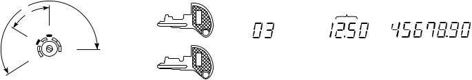
4. MODE SWITCH
1) LAYOUT
• Rotary type
Manager key (MA)
MA
OP |
|
MA |
|
|
|
OPX/Z |
REG |
|
MGR |
|
|
|
|
|
OFF |
X1/Z1 |
Operator key (OP) |
VOID |
X2/Z2 |
OP |
PGM |
|
|
|
|
The mode switch can be operated by inserting one of the two supplied mode keys - manager (MA) and operator (OP) keys. These keys can be inserted or removed only in the “REG” or “OFF” position.
The mode switch has these settings:
OFF : This mode locks all register operations. (AC power turns off.) No change occurs to register data.
OP X/Z: To take individual clerk X or Z reports, and to take flash reports.
|
It can be used to toggle receipt state “ON” and “OFF” by |
|
pressing he [RCPT/PO] key. |
REG |
: For entering sales. |
PGM |
: To program various items. |
VOID |
: Enters into the void mode. This mode allows correction after |
|
finalizing a transaction. |
MGR |
: For manager’s entries. The manager can use this mode for |
|
an override entry. |
X1/Z1 : To take the X/Z report for various daily totals.
X2/Z2 : To take the X/Z report for periodic (weekly or monthly) consolidation.
5. DISPLAY
1) OPERATOR DISPLAY
Display device |
|
|
|
: LED |
||||||||
Number of line |
|
|
|
: |
1 line |
|||||||
Number of positions: 10 positions |
||||||||||||
Color of display |
: Yellow Green |
|||||||||||
Character form |
|
|
|
: |
7 segment + DP |
|||||||
Character size |
|
|
|
: 14.2 (H) × 7.9 (W) mm |
||||||||
Layout: |
|
|
|
|
|
|
|
|||||
0 . 1 . 2 . 3 . 4 . 5 . 6 . 7 . 8 . 9 . |
||||||||||||
2) CUSTOMER DISPLAY |
||||||||||||
Display device |
|
|
|
: LED |
||||||||
Number of line |
|
|
|
: |
1 line |
|||||||
Number of positions: 7 positions |
||||||||||||
Color of display |
: Yellow Green |
|||||||||||
Style |
|
|
|
: Pop up type |
||||||||
Character form |
|
|
|
: 7 segment + Dp |
||||||||
Character size |
|
|
|
: 14.2mm (H) × 7.9mm (W) |
||||||||
Layout: |
|
|
|
|
|
|
|
|||||
3 . 4 . 5 . 6 . 7 . 8 . 9 . |
||||||||||||
Operator display |
|
|
|
Customer display |
||||||||
|
|
PLU/SUB |
|
|
|
|
|
|
(Pop-up type) |
|||
|
|
|
|
|
|
|
|
|
||||
|
|
DEPT REPEAT |
|
|
|
Clerk code |
||||||
|
|
|
|
|||||||||
|
|
|
|
|
|
|
|
|
|
|
|
|
|
|
|
|
|
|
|
|
|
|
|
|
|
|
|
RCPT |
DC |
SHIFT NUMBER |
||||||||
|
|
OFF |
|
|
|
|
|
|
|
|||
Amount: Appears in the far-right eight (max.) positions. When the amount is negative, the minus symbol “-” appears before the amount.
Number of repeats for repetitive registrations:
The number of repeats is displayed, starting at “2” and incremental with each repeat. When you have registered ten times, the display will show “0.” (2 3 3 ..... 9 3 0 3 1 3 2 ... )
Receipt function status:
The indicator “_” appears in the RCPT OFF position when the receipt function is in the OFF status.
Time : Appears in the far-right six positions (hour-minute - “
 ” or hour-minute - “
 ”) in the OP X/Z, REG, or MGR mode. “
 ” is displayed in the morning (AM), and “
 ” in the afternoon (PM). In the REG or MGR mode, press the [#/TM/SBTL] key to display the time.
XE-A21S SPECIFICATIONS
– 2 –

■Machine state symbols
: Appears during programming.
: Appears when an error is detected.
: Appears when the subtotal is displayed or when the amount tendered is smaller than the sales amount.
: Appears when the [CONV] key is pressed to calculate a subtotal in foreign currency.
Decimal Point
|
Display |
Description |
|
position |
|
|
|
|
|
|
|
Decimal point |
7-1 |
|
|
|
|
TAB |
4-1 |
|
|
|
|
EJ near full |
8, 9 |
(by PGM selection) |
|
|
|
: Appears when a transaction is finalized by pressing the [CA/AT/ NS], [CHK] or [CH] key.
: Appears when the change due amount is displayed.
: May appear in the far-left three positions at the timing of key entry when the electronic journal (EJ) memory is full. (Depending on programming.)
: Appears when the voltage of the installed batteries is under the required level. You must replace with new ones within two days.
: Appears when the batteries are not installed, or the installed batteries are dead. You must replace with new ones immediately.
: May appear right below the eighth and ninth places at the timing of finalization of a transaction when the electronic journal (EJ) memory is nearly full.
Also appears right below the tenth place when power save mode is effective.
: Appears when the print roller arm is not locked.


 : Appears when the paper is not set or has run out.
Segment
|
Display |
|
Description |
|
position |
|
|
|
|
|
|
|
|
|
|
Amount |
1-8 |
|
|
|
|
|
|
Minus sign |
2-10 |
- |
: Floating |
|
|
|
|
Error |
8-10 |
Exx : xx = error code |
|
PGM Mode |
10 |
P |
|
|
|
|
|
CASH, CHECK, |
10 |
F : Light up when a registration is |
|
CHARGE |
|
|
f i n a l i ze d by d e p r e s s i n g |
|
|
|
[CASH], [CHECK], [CHARGE] |
|
|
|
key |
|
|
|
|
SUB TOTAL/ |
10 |
o |
|
short tender |
|
|
|
|
|
|
|
Change |
10 |
C : Light up whenever the change |
|
|
|
|
due amount appears in the dis- |
|
|
|
play. |
|
|
|
|
Currency |
10 |
c : Light up whenever the foreign |
|
Conversion |
|
|
amount appears in the display. |
|
|
|
|
Department |
9-10 |
No zero-suppressed |
|
|
|
|
|
PLU |
7-10 |
No zero-suppressed |
|
|
|
|
|
Repeat |
8 |
Endless count, starting from 2. |
|
|
|
|
|
Receipt OFF |
9 |
_ |
|
|
|
|
|
DC |
|
_ |
: Double size character entry |
|
|
|
status |
|
|
|
|
SHIFT |
|
_ |
: Shift character entry status |
|
|
|
|
NUMBER |
|
_ |
: Number character entry status |
|
|
|
|
Clerk No. |
2, 3 |
-xx- : clerk number |
|
|
|
|
|
EJ FULL |
8-10 |
E-E : Light up when EJ memory is |
|
|
|
|
FULL at the timing of key entry |
|
|
|
(by PGM selection). |
|
|
|
|
Low Battery |
10 |
L |
: |
|
|
|
|
No Battery |
10 |
|
: |
|
|
|
|
6. PRINTER
1) Printer
• Part number |
: M-T53II |
|
|
• NO. of station |
: 1 (Receipt or journal) |
||
• Validation |
: No. |
|
|
• Printing system |
: Line thermal |
|
|
• No. of dot |
: 288 dots |
|
|
• Dot pitch |
: Horizontal |
|
0.167mm |
|
Vertical |
|
0.174mm |
• Font |
: 10 dots (W) × 24 dots (H) |
||
• Printing capacity |
: max. 24 characters |
|
|
• Character size |
: 1.67mm (W) × 4.17mm (H) at 10 × 24 dots |
||
• Print pitch |
: Column distance |
2.0mm |
|
|
Row distance |
|
5.21mm |
• Max. Print speed |
: Approximate 60mm/s (Approximate 12 l/s) |
||
• Max. Paper feed speed: Approximate 60mm/s (Approximate 12 l/s) |
|||
(Manual feed) |
: Approximate 40mm/s (Approximate 12 l/s) |
||
• Reliability |
: Mechanism LIFE 6 million lines used to |
||
|
high-quality thermal paper |
||
• Paper end sensor |
: Set up |
|
|
• Cutter |
: No |
|
|
• Near end sensor |
: No |
|
|
2) Paper |
|
|
|
• Paper roll dimension: |
57.5 ± 0.5mm in width |
||
|
Max. 80mm |
in diameter |
|
• Paper quality: |
High-quality thermal paper |
||
|
paper thickness |
|
: 0.06 to 0.08mm |
|
Nihon seisi thermal paper : TF50KS-E |
||
|
Oji thermal paper |
: PD150R, |
|
|
|
|
PD160R |
3) Logo stamp
• No
XE-A21S SPECIFICATIONS
– 3 –
4) PRINTING AREA
Number of thermal head heater elements 288 dots
(4.75) |
48 (288 dots) |
(4.75) |
|
print area |
|
|
(max.24 characters) |
|
|
0.167 |
|
|
57.5±0.5 |
(units : mm) |
|
|
|
|
(Paper dimension) |
|
7. DRAWER
[OUTLINE]
• Standard equipment |
: Yes (1) |
• Max. number of additional drawers: 1 |
|
• The drawer consists of |
: |
1)Drawer box (outer case) and drawer
2)Money case
3)Coin case
4)Lock (attached to the drawer)
[SPECIFICATION]
1) DRAWER BOX AND DRAWER
Model name of the drawer box |
SJ415 |
|
|
Size |
330(W) ×418(D) ×98(H) mm |
Material |
Plastic |
|
|
Bell |
— |
|
|
Release lever |
Standard equipment: |
|
situated at the bottom |
|
|
Drawer open sensor |
— |
|
|
2)MONEY CASE |
|
|
|
Separation from the drawer |
Disallowed |
|
|
Separation of the bill compart- |
Allowed |
ments from the coin compartments |
|
|
|
Bill separator |
— |
|
|
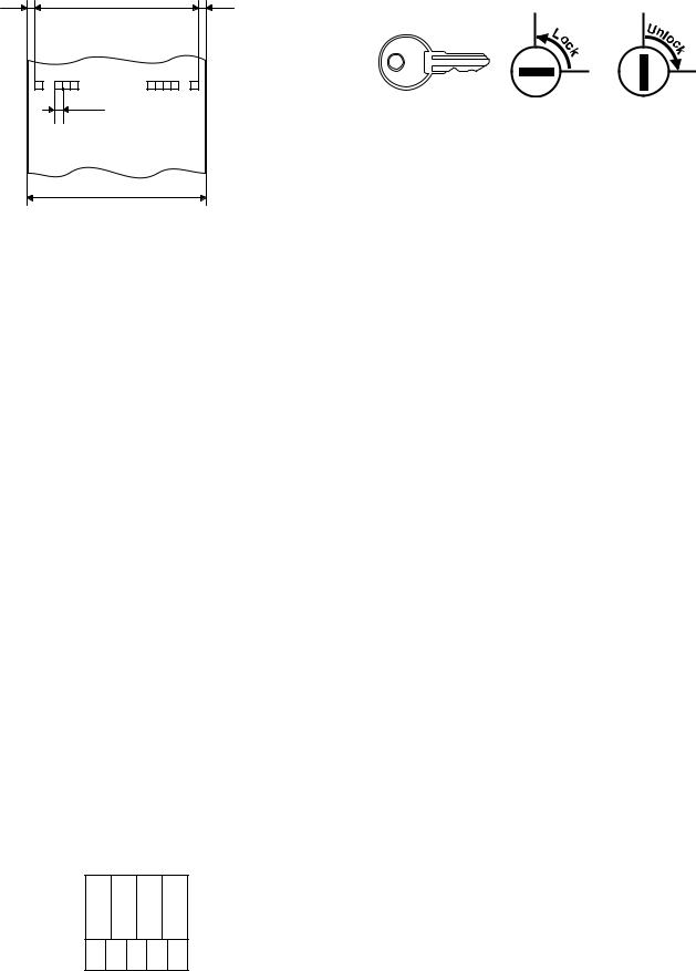
Number of compartments |
4B/5C |
|
|
Layout:
3) Drawer Lock Key
This key locks and unlocks the drawer. To lock it, turn 90 degrees counterclockwise. To unlock it, turn 90 degrees clockwise.
8. USB PORT
[DEVICE]
USB B Type
[OUTLINE]
This ECR has 1 port.
This is used in order to connect with a personal computer.
[SPECIDICATIONS]
1) Transmission rate
USB 2.0 Full Speed Max. 12Mbps
2) Connector
USB B Type
3) Pin assign
1Pin 5V
2Pin −D
3Pin +D
4Pin GND
9. BATTERY
1) MEMORY BACK UP BATTERY
For memory back up, the dry battery AA (3 pieces) are needed.
1.Memory holding time:
Approximate 1 year after New dry batteries are inserted.
2.Battery exchange method:
When the low battery symbol “L” lights up, batteries (3 pieces) exhange by the following method, with 2 days.
1)Power on the ECR.
2)Mode switch turn to “REG” mode.
3)Release the OLD dry batteries (3 pieces).
4)Insert the NEW dry batteries (3 pieces).
5)Confirm the low battery symbol “L” lights off.
2) LOW BATTERY
Low battery indication will appear on the left side of display when the battery voltage is low.
CASE 1: When any numeric entry & any item entry is not done or just
after finalization.
4B/5C
The machine can indicate the low battery condition. (Always)
XE-A21S SPECIFICATIONS
– 4 –
CASE 2: When numeric entry or item entry is done.
Battery condition will not appear.
Exceptionally, when the power is restored after a power failure, the low battery condition will appear on the display only when the battery is low.
And the indicator will disappear after any key entry.
[Display sample]
“0.00”: Battery is OK.
“L 0.00”: Low battery (You have to change the batteries.)
“ 0.00”: No battery (You have to change the batteries immediately.)
After finalization
“F 12.34”: Battery is OK.
“L 12.34”: Low battery. (“L” indicate instead of “F”.)
“ 12.34”: No battery. (“L” indicate instead of “F”.)
Note: “NO BATTERY”: When the “NO BATTERY” is display, the master reset is executed at the timing of “POWER ON” after the “POWER OFF”.
10. SD MEMORY CARD
[Device]
SD Card (Version. 1.01)
[Outline]
XE-A21S has a SD Memory Card slot.
[Specidications]
1) |
Variable clock rate |
: 0 - 25 MHZ |
2) |
Other commands and memory access : 2.7 - 3.6V |
|
3) |
Bus Protocol |
: SPI Bus |
4) |
Correspondence capacity |
: 32MB - 512MB |
5) |
Recommended manufacturer |
: SanDisk |
CHAPTER 2. OPTIONS
1. |
OPTIONS (NO) |
|
|
|
|
2. |
SERVICE OPTIONS (NO) |
|
|
|
|
3. |
SUPPLIES |
|
|
|
|
|
|
|
|
|
|
|
No. |
NAME |
PARTS CODE |
PRICERANK |
DESCRIPTION |
|
|
|
|
|
|
|
1 |
Thermal roll paper |
TPAPR6656RC05 |
BA |
5 ROLLS/PACK (70 φ) |
|
|
|
|
|
|
4. |
SPECIAL SERVICE TOOLS (NO) |
|
|
||
|
|
|
|
|
|
|
No. |
NAME |
PARTS CODE |
PRICERANK |
DESCRIPTION |
|
|
|
|
|
|
|
1 |
USB Cable |
|
|
|
|
|
|
|
|
|
CHAPTER 3. MASTER RESET AND PROGRAM RESET
1. MASTER RESETTING
Master resetting clears the entire memory and resumes initial values. Master resetting can be accomplished by using the following procedure:
Procedure A: 1) Unplug the AC cord from the wall outlet or set the mode switch to OFF Position.
2)Let the ECR be without the memory back up battery.
3)Wait over 1 muinite for discharging.
4)Set the mode switch to any position except OFF.
5)Plugin the AC cord to the wall outlet or turn the mode switch from OFF Position to another position.
The master reset can also be accomplished in the following case.
In case power failure occurs when the machine has no battery attached to it, the master reset operation is automatically performed after the power has been restored.
(This is because if power failure occurs with no battery attached to the machine, all the memories are lost and the machine does not work properly after power recovery; this requires the master reset operation.)
2.PROGRAM RESETTING (INITIALIZATION)
This resetting resumes the initial program without clearing memory.
This resetting can be operated at below sequence in PGM mode.
Procedure: 1) |
Unplug the AC cord from the wall outlet. |
2) |
Wait over 1 muinite for discharging. |
3) |
Set the mode switch to the PGM position. |
4) |
While holding down the FEED key, plugin the AC |
|
cord to the wall outlet. |
Note: In case power failure occurs when the machine has no battery attached to it, the master reset operation is automatically performed after the power has been restored.
XE-A21S OPTIONS
– 5 –

CHAPTER 4. HARDWARE DESCRIPTION
1. HARDWARE BLOCK DIAGRAM |
2. MEMORY MAP |
POWER |
DRY Battery |
|
|
|
5.8V |
|
BUZZER |
|
|
5.0V |
|
|
||
|
|
|
|
|
3.3V |
|
|
|
|
7.9V |
|
|
|
|
23.8V |
|
|
|
|
12MHz |
CPU |
|
RESET IC |
|
|
|
|
||
|
Renesus |
|
|
|
32.768kHz |
M30624MWP- |
|
LV125 |
SD CARD |
|
XXXFP |
|
HCT04 |
|
DRAWER |
|
|
||
|
|
|
||
ROM 320KByte |
|
|
||
|
|
|
||
|
RAM 24KByte |
|
|
|
Driver/Sensor |
|
S-RAM |
|
|
|
|
|
128KByte |
|
PRINTER |
|
|
|
|
MT53II |
|
|
USB |
USB |
|
|
|
Controller |
Type B |
|
|
|
|
|
|
|
|
M66291GP |
|
MOTOR |
|
|
|
|
|
74H374 |
|
SEG |
|
|
|
Driver |
LED |
|
|
|
|
||
|
|
|
|
Front 10 |
|
|
|
DIG |
PopUp 7 |
|
Decoder |
|
|
|
|
|
Driver |
|
|
|
74HC138 |
2 |
|
|
|
|
|
||
|
4 to 16 |
|
KEY SCAN |
KEY |
|
|
|
|
|
|
|
|
KEY RETURN |
SWITCH |
<Main parts>
CPU |
: M30624MWP-XXXFP (Renesus) |
|
ROM 320KByte (MASK) RAM 24KByte |
External RAM |
: 1Mbit (128K × 8) |
|
CYPRESS CY62128BLL-70SXI |
Printer |
: MT53II (EPSON) |
USB controller |
: M66291GP (Renesus) |
1MByte mode/The CS area PM13 = 1 is selected.
CPU internal RAM |
: 24KByte 00400h-063FFh |
External RAM |
: 128KByte 08000h-27000h |
|
(Area that can be used 124KByte) |
00000h
00400h CPU internal RAM 24KByte 00400h-063FFh
063FFh
06400h
08000h External RAM |
|
/CS2 |
|
||
128KByte |
|
|
|
|
|
27000h |
|
|
|
|
|
|
|
28000h |
USB controller |
|
/CS1 |
|
|||
|
|
|
|
|
|
|
|
30000h |
Segment Latch Address |
|
/CS0 |
|
|||
|
|
|
|
80000h
B0000h CPU internal MASK ROM 320KByte B0000h-FFFFFh
FFFFFh
XE-A21S HARDWARE DESCRIPTION
– 6 –
3. CPU PORT
Port |
Pin No. |
Pin name |
Signal name |
I/O |
Initial value |
Off mode |
Function |
|
|
|
|
|
|
|
|
P00 |
88 |
D0 |
D0 |
I/O |
H |
Out L |
DATE BUS D0 |
|
|
|
|
|
|
|
|
P01 |
87 |
D1 |
D1 |
I/O |
H |
Out L |
DATE BUS D1 |
|
|
|
|
|
|
|
|
P02 |
86 |
D2 |
D2 |
I/O |
H |
Out L |
DATE BUS D2 |
|
|
|
|
|
|
|
|
P03 |
85 |
D3 |
D3 |
I/O |
H |
Out L |
DATE BUS D3 |
|
|
|
|
|
|
|
|
P04 |
84 |
D4 |
D4 |
I/O |
H |
Out L |
DATE BUS D4 |
|
|
|
|
|
|
|
|
P05 |
83 |
D5 |
D5 |
I/O |
H |
Out L |
DATE BUS D5 |
|
|
|
|
|
|
|
|
P06 |
82 |
D6 |
D6 |
I/O |
H |
Out L |
DATE BUS D6 |
|
|
|
|
|
|
|
|
P07 |
81 |
D7 |
D7 |
I/O |
H |
Out L |
DATE BUS D7 |
|
|
|
|
|
|
|
|
P10 |
80 |
P10 |
KST0 |
O |
L |
In |
KEY DISPLAY (4 TO 16) |
|
|
|
|
|
|
|
|
P11 |
79 |
P11 |
KST1 |
O |
L |
In |
KEY DISPLAY (4 TO 16) |
|
|
|
|
|
|
|
|
P12 |
78 |
P12 |
KST2 |
O |
L |
In |
KEY DISPLAY (4 TO 16) |
|
|
|
|
|
|
|
|
P13 |
77 |
P13 |
KST3 |
O |
L |
In |
KEY DISPLAY (4 TO 16) |
|
|
|
|
|
|
|
|
P14 |
76 |
P14 |
IN2 |
O |
L |
Out L |
PAPER FEED MOTOR |
|
|
|
|
|
|
|
|
P15 |
75 |
P15 |
IN1 |
O |
L |
Out L |
PAPER FEED MOTOR |
|
|
|
|
|
|
|
|
P16 |
74 |
P16 |
ENA2 |
O |
L |
Out L |
PAPER FEED MOTOR |
|
|
|
|
|
|
|
|
P17 |
73 |
P17 |
ENA1 |
O |
L |
Out L |
PAPER FEED MOTOR |
|
|
|
|
|
|
|
|
P20 |
72 |
A0 |
A0 |
O |
H |
Out L |
ADDRESS BUS A0 |
|
|
|
|
|
|
|
|
P21 |
71 |
A1 |
A1 |
O |
H |
Out L |
ADDRESS BUS A1 |
|
|
|
|
|
|
|
|
P22 |
70 |
A2 |
A2 |
O |
H |
Out L |
ADDRESS BUS A2 |
|
|
|
|
|
|
|
|
P23 |
69 |
A3 |
A3 |
O |
H |
Out L |
ADDRESS BUS A3 |
|
|
|
|
|
|
|
|
P24 |
68 |
A4 |
A4 |
O |
H |
Out L |
ADDRESS BUS A4 |
|
|
|
|
|
|
|
|
P25 |
67 |
A5 |
A5 |
O |
H |
Out L |
ADDRESS BUS A5 |
|
|
|
|
|
|
|
|
P26 |
66 |
A6 |
A6 |
O |
H |
Out L |
ADDRESS BUS A6 |
|
|
|
|
|
|
|
|
P27 |
65 |
A7 |
A7 |
O |
H |
Out L |
ADDRESS BUS A7 |
|
|
|
|
|
|
|
|
P30 |
63 |
A8 |
A8 |
O |
H |
Out L |
ADDRESS BUS A8 |
|
|
|
|
|
|
|
|
P31 |
61 |
A9 |
A9 |
O |
H |
Out L |
ADDRESS BUS A9 |
|
|
|
|
|
|
|
|
P32 |
60 |
A10 |
A10 |
O |
H |
Out L |
ADDRESS BUS A10 |
|
|
|
|
|
|
|
|
P33 |
59 |
A11 |
A11 |
O |
H |
Out L |
ADDRESS BUS A11 |
|
|
|
|
|
|
|
|
P34 |
58 |
A12 |
A12 |
O |
H |
Out L |
ADDRESS BUS A12 |
|
|
|
|
|
|
|
|
P35 |
57 |
A13 |
A13 |
O |
H |
Out L |
ADDRESS BUS A13 |
|
|
|
|
|
|
|
|
P36 |
56 |
A14 |
A14 |
O |
H |
Out L |
ADDRESS BUS A14 |
|
|
|
|
|
|
|
|
P37 |
55 |
A15 |
A15 |
O |
H |
Out L |
ADDRESS BUS A15 |
|
|
|
|
|
|
|
|
P40 |
54 |
A16 |
A16 |
O |
H |
Out L |
ADDRESS BUS A16 |
|
|
|
|
|
|
|
|
P41 |
53 |
A17 |
A17 |
O |
H |
Out L |
ADDRESS BUS A17 |
|
|
|
|
|
|
|
|
P42 |
52 |
A18 |
A18 |
O |
H |
Out L |
ADDRESS BUS A18 |
|
|
|
|
|
|
|
|
P43 |
51 |
A19 |
A19 |
O |
H |
Out L |
ADDRESS BUS A19 |
|
|
|
|
|
|
|
|
P44 |
50 |
/CS0 |
/CS0 |
O |
H |
Out L |
SEGMENT LATCH |
|
|
|
|
|
|
|
|
P45 |
49 |
/CS1 |
/CS1 |
O |
H |
Out L |
USB CONTROLLER |
|
|
|
|
|
|
|
|
P46 |
48 |
/CS2 |
/CS2 |
O |
H |
Out H |
SRAM |
|
|
|
|
|
|
|
|
P47 |
47 |
/CS3 |
(NU) |
O |
L |
Out L |
UNUSED |
|
|
|
|
|
|
|
|
P50 |
46 |
/WR |
/WR |
O |
H |
Out L |
WRITE STROBE SIGNAL |
|
|
|
|
|
|
|
|
P51 |
45 |
/BHE |
(NU) |
O |
L |
Out L |
UNUSED |
|
|
|
|
|
|
|
|
P52 |
44 |
/RD |
/RD |
O |
H |
Out L |
READ STROBE SIGNAL |
|
|
|
|
|
|
|
|
P53 |
43 |
BCLK |
(NU) |
O |
L |
Out L |
UNUSED |
|
|
|
|
|
|
|
|
P54 |
42 |
/HLDA |
(NU) |
O |
L |
Out L |
UNUSED |
|
|
|
|
|
|
|
|
P55 |
41 |
/HOLD |
/EPM |
I |
- |
In |
|
|
|
|
|
|
|
|
|
P56 |
40 |
ALE |
(NU) |
O |
L |
Out L |
UNUSED |
|
|
|
|
|
|
|
|
P57 |
39 |
/RDY |
/RDY |
I |
- |
In |
VCC PULLUP |
|
|
|
|
|
|
|
|
P60 |
38 |
P60 |
DR1 |
O |
L |
Out L |
DRAWER DRIVE SIGNAL |
|
|
|
|
|
|
|
|
P61 |
37 |
P61 |
SD_CLK |
O |
H |
Out L |
SD CLK |
|
|
|
|
|
|
|
|
P62 |
36 |
P62 |
SD_RXD |
I |
- |
In |
SD RXD |
|
|
|
|
|
|
|
|
P63 |
35 |
P63 |
SD_TXD |
O |
H |
Out L |
SD TXD |
|
|
|
|
|
|
|
|
XE-A21S HARDWARE DESCRIPTION
– 7 –
Port |
Pin No. |
Pin name |
Signal name |
I/O |
Initial value |
Off mode |
Function |
|
|
|
|
|
|
|
|
P64 |
34 |
P64 |
SD_POWER# |
O |
H |
Out L |
SD POWER# |
|
|
|
|
|
|
|
|
P65 |
33 |
P65 |
SD_CS# |
O |
H |
Out L |
SD CS# |
|
|
|
|
|
|
|
|
P66 |
32 |
P66 |
SD_CD# |
I |
- |
In |
SD CD# |
|
|
|
|
|
|
|
|
P67 |
31 |
P67 |
SD_WP# |
I |
- |
In |
SD WP# |
|
|
|
|
|
|
|
|
P70 |
30 |
TXD2 |
DAT |
O |
L |
Out L |
PRINTER DATA OUT |
|
|
|
|
|
|
|
|
P71 |
29 |
P71 |
(NU) |
O |
L |
Out L |
UNUSED |
|
|
|
|
|
|
|
|
P72 |
28 |
CLK2 |
CLK |
O |
L |
Out L |
PRINTER CLOCK |
|
|
|
|
|
|
|
|
P73 |
27 |
P73 |
(NU) |
O |
L |
Out L |
UNUSED |
|
|
|
|
|
|
|
|
P74 |
26 |
P74 |
P74 |
I |
- |
In |
MODEL JUDGMENT |
|
|
|
|
|
|
|
|
P75 |
25 |
P75 |
P75 |
I |
- |
In |
MODEL JUDGMENT |
|
|
|
|
|
|
|
|
P76 |
24 |
P76 |
/RES_USB |
O |
L |
Out L |
USB RESET |
|
|
|
|
|
|
|
|
P77 |
23 |
P77 |
/EPM CTRL |
O |
H |
Out L |
/EPM CONTROL SIGNAL WHEN IPL |
|
|
|
|
|
|
|
|
P80 |
22 |
P80 |
BUZZER |
O |
L |
Out L |
BUZZER |
|
|
|
|
|
|
|
|
P81 |
21 |
P81 |
MOTOR |
O |
L |
Out L |
PAPER TAKE UP MOTOR |
|
|
|
|
|
|
|
|
P82 |
20 |
/INT0 |
POFF |
I |
- |
In |
POWER INTERRUPT |
|
|
|
|
|
|
|
|
P83 |
19 |
/INT1 |
/DREQUSB |
I |
- |
In |
USB DMA REQUEST |
|
|
|
|
|
|
|
|
P84 |
18 |
/INT2 |
/INTUSB |
I |
- |
In |
USB INTERRUPT |
|
|
|
|
|
|
|
|
P85 |
17 |
/NMI |
(NU) |
I |
- |
In |
UNUSED |
|
|
|
|
|
|
|
|
P86 |
11 |
XCOUT |
XCOUT |
I |
- |
In |
32.768kHz |
|
|
|
|
|
|
|
|
P87 |
10 |
XCIN |
XCIN |
I |
- |
In |
32.768kHz |
|
|
|
|
|
|
|
|
P90 |
7 |
P90 |
P90 |
I |
- |
In |
KEY IN |
|
|
|
|
|
|
|
|
P91 |
6 |
P91 |
P91 |
I |
- |
In |
KEY IN |
|
|
|
|
|
|
|
|
P92 |
5 |
P92 |
P92 |
I |
- |
In |
KEY IN |
|
|
|
|
|
|
|
|
P93 |
4 |
P93 |
P93 |
I |
- |
In |
KEY IN |
|
|
|
|
|
|
|
|
P94 |
3 |
P94 |
P94 |
I |
- |
In |
KEY IN |
|
|
|
|
|
|
|
|
P95 |
2 |
P95 |
P95 |
I |
- |
In |
KEY IN |
|
|
|
|
|
|
|
|
P96 |
1 |
P96 |
P96 |
I |
- |
In |
KEY IN |
|
|
|
|
|
|
|
|
P97 |
100 |
P97 |
P97 |
I |
- |
In |
KEY IN |
|
|
|
|
|
|
|
|
P100 |
97 |
AN0 |
P100 |
I |
- |
In |
HEAD TEMPERATURE MONITOR |
|
|
|
|
|
|
|
|
P101 |
95 |
AN1 |
P101 |
I |
- |
In |
HEAD VOLTAGE MONITOR |
|
|
|
|
|
|
|
|
P102 |
94 |
P102 |
/STB2 |
O |
H |
In |
PRINTER/STB2 |
|
|
|
|
|
|
|
|
P103 |
93 |
AN3 |
VBAT |
I |
- |
In |
BATTERY VOLTAGE |
|
|
|
|
|
|
|
|
P104 |
92 |
P104 |
(NU) |
O |
L |
Out L |
UNUSED |
|
|
|
|
|
|
|
|
P105 |
91 |
P105 |
VPON |
O |
L |
Out L |
PRINTER HEAD POWER |
|
|
|
|
|
|
|
|
P106 |
90 |
P106 |
/LAT |
O |
H |
Out L |
PRINTER DATA LATCH |
|
|
|
|
|
|
|
|
P107 |
89 |
P107 |
/STB1 |
O |
H |
In |
PRINTER/STB1 |
|
|
|
|
|
|
|
|
BYTE |
8 |
BYTE |
|
I |
- |
In |
CONNECTED TO VDD |
|
|
|
|
|
|
|
|
CNVss |
9 |
CNVss |
|
I |
- |
In |
NOMAL: L / BOOT: H |
|
|
|
|
|
|
|
|
/RESET |
12 |
/RESET |
|
I |
- |
In |
RESET |
|
|
|
|
|
|
|
|
Xout |
13 |
Xout |
|
O |
|
Out |
CLOCK |
|
|
|
|
|
|
|
|
Vss |
14 |
Vss |
|
power |
|
|
CONNECTED TO GND |
|
|
|
|
|
|
|
|
Xin |
15 |
Xin |
|
I |
|
In |
CLOCK |
|
|
|
|
|
|
|
|
Vcc |
16 |
Vcc |
|
power |
|
|
CONNECTED TO VDD |
|
|
|
|
|
|
|
|
Vcc |
62 |
Vcc |
|
power |
|
|
CONNECTED TO VDD |
|
|
|
|
|
|
|
|
Vss |
64 |
Vss |
|
power |
|
|
CONNECTED TO GND |
|
|
|
|
|
|
|
|
AVss |
96 |
AVss |
|
power |
|
|
CONNECTED TO GND |
|
|
|
|
|
|
|
|
Vref |
98 |
Vref |
|
ref |
|
|
CONNECTED TO VDD |
|
|
|
|
|
|
|
|
AVcc |
99 |
AVcc |
|
power |
|
|
CONNECTED TO VDD |
|
|
|
|
|
|
|
|
XE-A21S HARDWARE DESCRIPTION
– 8 –
4. USB PORT
One port for USB Port (Slave) is provided as a standard provision of XE-A21S.
The Renesus-make USB general-use ASSP device M66291 is used. The M66291 is mapped to the /CS1 area 28000h-29FFFh.
CPU |
M66291 |
|
|
|
|
|
A0 |
D15/AD0 |
|
|
|
|
|
A1-A6 |
AD1-AD6 |
VBuss |
|
|
|
|
|
|
|
|
|||
|
|
|
|
|
||
D0-D7 |
D0-D7 |
TrON |
1.5k |
|
|
|
|
|
|
1 |
|
||
/CS1 |
CS |
|
|
Vbus |
||
D+ |
|
3 |
||||
/RD |
RD |
|
D+ |
|||
27 |
2 |
|||||
/WR |
LWR |
D− |
||||
|
4 |
D− |
||||
/RESUSB |
/RESET |
27 |
||||
|
GND |
|||||
/DREQUSB |
/Dreq0 |
|
1.0 F |
|
||
/INTUSB |
/INT0 |
|
|
USB |
||
|
HWR/BYTE |
|
|
|
||
|
|
|
|
|
CONN- |
|
|
|
|
|
|
ECTOR |
|
|
24MHz |
|
|
|
|
|
<CPU PORT> |
|
|
|
|
|
No. |
CPU port |
Use signal |
Purpose |
|
|
|
|
19 |
P83 (INT1) |
/DREQUSB |
USB DMA channel 0 DMA request |
|
|
|
signal |
|
|
|
|
18 |
P84 (INT2) |
/INTUSB |
USB interruption 0 request signal |
|
|
|
|
24 |
P76 (TA3OUT) |
/RESUSB |
M66291 Reset control |
|
|
|
|
5. SD CARD I/F
One port for SD card I/F is provided as a standard provision of XE-A21S. Communication with the SD card is made in the SPI mode.
No. |
CPU port |
Use signal |
Purpose |
|
|
|
|
31 |
P67 (TXD1) |
/SD_WP |
SD card write protect detection signal |
|
|
|
|
32 |
P66 (RXD1) |
/SD_CD |
SD card insertion detection signal |
|
|
|
|
33 |
P65 (CLK1) |
/SD_CS |
SD card chip select signal |
|
|
|
|
34 |
P64 (CLKS1) |
/SD_POW |
SD card power on signal |
|
|
|
|
35 |
P63 (TXD0) |
SD_TXD |
TxD signal |
|
|
|
|
36 |
P62 (RXD0) |
SD_RXD |
RxD signal |
|
|
|
|
37 |
P61 (CLK0) |
SD_CLK |
Serial CLK signal |
|
|
|
|
6. PRINTER CONTROL
6-1. STEPPING MOTOR CONTROL
The two-phase bi-polar stepping motor is driven at a constant voltage. 1step: 0.087mm, 1dot: 2step
<CPU PORT>
Pin No. |
CPU port |
Use signal |
Function |
|
|
|
|
76 |
P14 |
IN2 |
Paper feed motor (IN2) |
|
|
|
|
75 |
P15 |
IN1 |
Paper feed motor (IN1) |
|
|
|
|
74 |
P16 |
ENA2 |
Paper feed motor (ENA2) |
|
|
|
|
73 |
P17 |
ENA1 |
Paper feed motor (ENA1) |
|
|
|
|
<DRIVE STEP>
|
Driver IC input (CPU output) |
|
Motor drive signal |
|
||||
|
|
|
|
|
|
|
|
|
STEP |
IN1 |
IN2 |
ENA1 |
ENA2 |
A |
B |
/A |
/B |
(OUT1) |
(OUT3) |
(OUT2) |
(OUT4) |
|||||
|
|
|
|
|
|
|
|
|
1 |
L |
L |
H |
H |
H |
H |
L |
L |
|
|
|
|
|
|
|
|
|
2 |
H |
L |
H |
H |
L |
H |
H |
L |
|
|
|
|
|
|
|
|
|
3 |
H |
H |
H |
H |
L |
L |
H |
H |
|
|
|
|
|
|
|
|
|
4 |
L |
H |
H |
H |
H |
L |
L |
H |
|
|
|
|
|
|
|
|
|
6-2. HEAD CONTROL
HEAD: All 288dot, Width 0.167mm/dot (6dot/mm)
<CPU PORT>
Pin No. |
CPU port |
Use signal |
Function |
|
|
|
|
89 |
P107 |
STRB1# |
Printer STB1# |
|
|
|
|
94 |
P102 |
STRB2# |
Printer STB2# |
|
|
|
|
30 |
P70 |
DAT |
Printer print data |
|
|
|
|
28 |
P72 |
PCLK |
Printer forwarding clock |
|
|
|
|
90 |
P106 |
LATCH# |
Printer data latch |
|
|
|
|
91 |
P105 |
VPON |
Printer head motor power |
|
|
|
|
6-3. PAPER TAKE UP MOTOR CONTROL
<CPU PORT>
Pin No. |
Port |
Use signal |
Function |
|
|
|
|
21 |
P81 |
MOTOR |
Printer paper take up motor |
|
|
|
|
6-4. OUT OF PAPER DETECTION
<CPU PORT>
Pin No. |
Port |
Strobe signal |
Function |
|
|
|
|
6 |
P91 |
/S4 |
Printer out of paper detection |
|
|
|
(It reads according to the timing of /S4) |
|
|
|
|
6-5. PLATEN OPEN (HEAD UP DETECTION)
<CPU PORT>
Pin No. |
Port |
Strobe signal |
Function |
|
|
|
|
6 |
P91 |
/S3 |
Platen open detection |
|
|
|
(It reads according to the timing of /S3) |
|
|
|
|
7. A/D CONVERSION
The following three signals are inputted to the A/D conversion port.
<CPU PORT>
PIN |
Port |
Use |
Function |
|
No. |
signal |
|||
|
|
|||
|
|
|
|
|
97 |
AN0/P100 |
TM |
Printer head temperature monitor |
|
|
|
|
|
|
95 |
AN1/P101 |
VPTEST |
Printer head voltage monitor |
|
|
|
|
|
|
93 |
AN3/P103 |
VBAT |
Battery voltage monitor |
|
|
|
|
|
XE-A21S HARDWARE DESCRIPTION
– 9 –
Loading...