


XL-560H/E,570H/E
SERVICE MANUAL
No. S5923XL560HE/
XL-560H/E
XL-570H/E
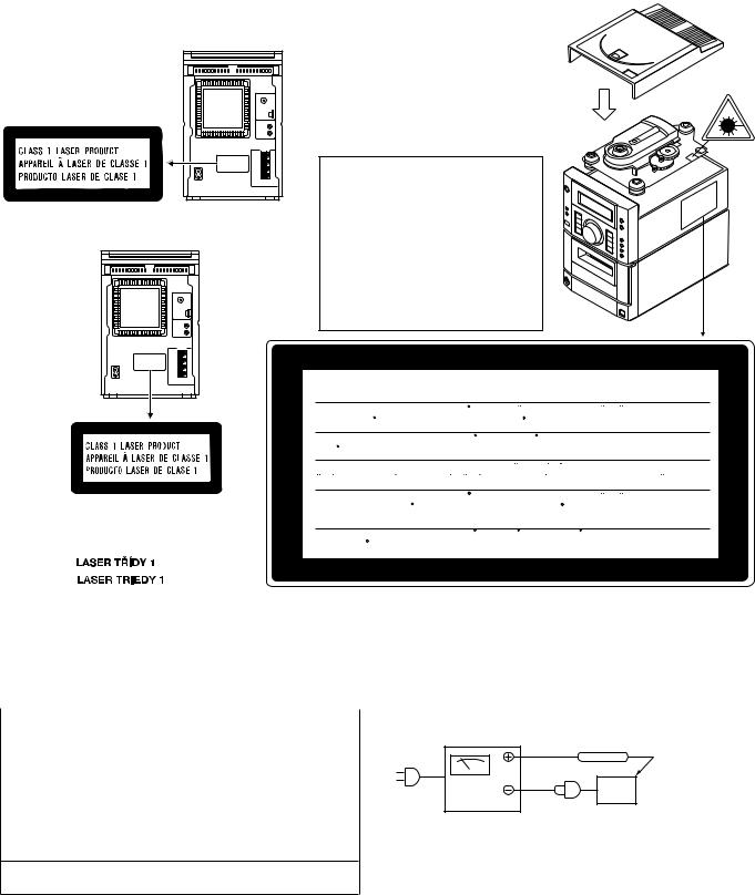
XL-560H micro component system consisting of XL560H micro component system and CP-XL560H speaker
|
system. |
|
|
XL-570H micro component system consisting of XL- |
|
Illustration: XL-560H/570H,CP-XL560H/570H |
570H micro component system and CP-XL570H speaker |
|
system. |
||
|
||
|
XL-560E micro component system consisting of XL- |
|
|
560E micro component system and CP-XL560H speaker |
|
|
system. |
|
|
XL-570E micro component system consisting of XL- |
|
|
570E micro component system and CP-XL570H speaker |
|
|
system. |
|
|
• In the interests of user-safety the set should be restored to its original |
|
|
condition and only parts identical to those specified should be used. |
Illustration: XL-560E/570E,CP-XL560H/570H
• Note for users in U.K.
Recording and playback of any material may require consent, which SHARP is unable to give. Please refer particularly to the provisions of Copyright Act 1956, the Dramatic and Musical
Performers Protection Act 1956, the Performers Protection Acts 1963 and 1972 and to any subsequent statutory enactments and orders.
DIFFERENCE BETWEEN
XL-560E/570E AND XL-560H/570H
SECTION |
XL-560E/570E |
XL-560H/570H |
RDS circuit |
None |
Used |
|
|
|
Surround circuit |
None |
Used |
|
|
|
CD Lid Panel |
XL-570E Only |
XL-570H Only |
|
|
|
Speaker Cord |
XL-570E Only |
XL-570H Only |
|
|
|
CONTENTS
Page
SAFETY PRECAUTION FOR SERVICE MANUAL ........................................................................................... |
............... 2 |
IMPORTANT SERVICE NOTES (XL-560E/570E FOR U.K. ONLY).......................................................................... |
....... 2 |
SPECIFICATIONS ................................................................................................................. |
........................................... 3 |
NAMES OF PARTS ................................................................................................................. |
......................................... 4 |
OPERATION MANUAL (FOR XL-560H/570H) ............................................................................................ |
..................... 6 |
DISASSEMBLY .................................................................................................................... |
............................................. 8 |
REMOVING AND REINSTALLING THE MAIN PARTS ....................................................................................... |
............. 9 |
ADJUSTMENT ..................................................................................................................... |
........................................... 10 |
RDS (RDS CIRCUIT IS ONLY FOR XL-560H/570H) .................................................................................... |
................. 11 |
TEST MODE ...................................................................................................................... |
............................................. 12 |
NOTES ON SCHEMATIC DIAGRAM ..................................................................................................... |
........................ 21 |
TYPE OF TRANSISTOR AND LED .................................................................................................... |
............................ 21 |
MEASURES TO BE TAKEN TO CHANGE THE MICROCOMPUTERS, STARTING FROM SERIAL No. 905xxxxx .... 21 |
|
BLOCK DIAGRAM .................................................................................................................. |
........................................ 22 |
SCHEMATIC DIAGRAM / WIRING SIDE OF P.W.BOARD .................................................................................. |
.......... 26 |
WAVEFORMS OF CD CIRCUIT ........................................................................................................ |
............................. 35 |
TROUBLESHOOTING ............................................................................................................... |
..................................... 36 |
FUNCTION TABLE OF IC ........................................................................................................... |
................................... 42 |
LCD SEGMENT ................................................................................................................... |
........................................... 50 |
PARTS GUIDE/EXPLODED VIEW |
|
PACKING METHOD (XL-560E/570E FOR U.K. ONLY) |
|
|
This document has been published to be used |
SHARP CORPORATION |
for after sales service only. |
– 1 – |
The contents are subject to change without notice. |
XL-560H/E,570H/E
SAFETY PRECAUTION FOR SERVICE MANUAL
Precaution to be taken when replacing and servicing the Laser Pickup.
The AEL (Accessible Emission Level) of Laser Power Output for this model is specified to be lower than Class I Requirements. However, the following precautions must be observed during servicing to protect your eyes against exposure to the Laser beam
(1)When the cabinet has been removed, the power is turned on without a compact disc, and the Pickup is on a position outer than the lead-in position, the Laser will light for several seconds to detect a disc. Do not look into the Pickup Lens.
(2)The Laser Power Output of the Pickup inside the unit and replacement service parts have already been adjusted prior to shipping.
(3)No adjustment to the Laser Power should be attempted when replacing or servicing the Pickup.
(4)Under no circumstances look directly into the Pickup Lens at any time.
(5)CAUTION - Use of controls or adjustments, or performance of procedures other than those specified herein may result in hazardous radiation exposure.
(For U.K. /Thailand)
(FOR Europe)
LASER KLASSE 1
LUOKAN 1 LASERLAITE
KLASS 1 LASERAPPARAT
Laser Diode Properties
Material: GaAIAs
Wavelength: 780 nm
Emission Duration: continuous
Laser Output: max. 0.6 mW
VAROITUS! LAITTEEN KÄYTTÄMINEN
MUULLA KUIN TÄSSÄ
K ÄY T TÖ OHJE ES SA MA I NI TU LL A
T A VA LL A SA AT T AA AL T IS TA A
KÄYTTÄJÄN TURVALLISUUSLUOKAN 1
Y L IT T ÄV ÄL L E NÄ KYMÄT TÖMÄ LL E
LASERSÄTEILYLLE.
VARNING - OM APPARATEN ANVÄNDS PÅ
A NNA T SÄT T ÄN I DENN A
BRUKSANVISNING SPECIFICERAS. KAN
ANVÄNDAREN UTSÄTTAS FÖR OSYNLIG
LASERSTRÅLNING, SOM ÖVERSKRIDER
GRÄNSEN FÖR LASERKLASS 1.
CAUTION-INVISIBLE LASER RADIATION WHEN OPEN. DO NOT STARE INTO BEAM OR VIEW DIRECTLY WITH OPTICAL INSTRUMENTS.
VARNING-OSYNLIG LASERSTRALNING NAR DENNA DEL AR OPPNAD. STIRRA EJ IN I STRALEN OCH BETRAKTA EJ STRALEN MED OPTISKA INSTRUMENT.
ADVERSEL-USYNLIG LASERSTRALING VED ABNING. SE IKKE IND I STRALEN-HELLER IKKE MED OPTISKE INSTRUMENTER.
VARO! AVATTAESSA OLET ALTTIINA NAKYMATON LASERSATEILYLLE. ALA TUIJOTA SATEESEEN ALAKA KATSO SITA OPTISEN LAITTEEN LAPI.
VARNING-OSYNLIG LASERSTRALNING NAR DENNA DEL AR OPPNAD. STIRRA EJ IN I STRALEN OCH BETRAKTA EJ STRALEN GENOM OPTISKT INSTRUMENT.
ADVERSEL-USYNLIG LASERSTRALING NAR DEKSEL APNES. STIRR IKKE INN I STRALEN ELLER SE DIREKTE MED OPTISKE INSTRUMENTER.
IMPORTANT SERVICE NOTES (XL-560E/570E FOR U.K. ONLY)
Before returning the unit to the customer after completion of a repair or adjustment it is necessary for the following withstand voltage test to be applied to ensure the unit is safe for the customer to use.
Setting of Withstanding Voltage Tester and set.
Set name |
set value |
|
|
Withstanding Voltage Tester |
|
|
|
Test voltage |
4,240 VPEAK |
|
3,000 VRMS |
|
|
Set time |
6 secs |
|
|
Set current(Cutoff current) |
4 mA |
|
|
Unit |
|
|
|
Judgment |
|
OK: The “GOOD” lamp lights.
NG: The “NG” lamp lights and the buzzor sounds.
WITHSTANDING
VOLTAGE TESTER
PROBE
AC
OUT
UNIT
SHORT-CIRCUT |
CONNECT THE PROBE |
AC POWER |
TO GND OF CHASSIS |
SUPPLY CORD |
SCREW TERMINAL |
– 2 –
XL-560H/E,570H/E
FOR A COMPLETE DESCRIPTION OF THE OPERATION OF THIS UNIT, PLEASE REFER TO THE OPERATION MANUAL.
SPECIFICATIONS
XL-560H/570H
■ Main unit ● General
Power source: |
AC 230 V, 50 Hz |
Power |
Stand-by; 0.6 W |
consumption: |
Power on; 50 W |
Dimensions: |
Width; 160 mm (6-5/16") |
|
Height; 241 mm (9-1/2") |
Weight: |
Depth; 298 mm (11-3/4") |
3.3 kg (7.3 lbs.) |
● Amplifier section
Output power: PMPO; 112 W (Total)
MPO; 60 W (30 W + 30 W) (DIN 45 324)
RMS; 40 W (20 W + 20 W) (DIN 45 324)
Output terminals: Speakers; 4 ohms Headphones; 16-50 ohms (recommended; 32 ohms) CD digital output (optical)
Input terminals: Video/Auxiliary (audio signal); 500 mV/47 kohms
● Tuner section
Frequency range: FM; 87.5-108 MHz
AM; 522-1,620 kHz
● Compact disc player section
Type: |
Compact disc player |
Signal readout: |
Non-contact, 3-beam semi- |
D/A converter: |
conductor laser pickup |
1-bit D/A converter |
|
Filter: |
8-times oversampling digital filter |
Frequency |
|
response: |
20 - 20,000 Hz |
Wow and flutter: |
Unmeasurable |
|
(less than 0.001% W. peak) |
● Cassette deck section
Frequency |
50 - 14,000 Hz |
response: |
(Normal tape) |
Signal/noise ratio: |
50 dB |
Wow and flutter: |
0.3 % (DIN 45 511) |
CP-XL570H
■ Speaker
Type: |
2-way [12 cm (4-3/4") |
|
woofer and 2.5 cm (1") |
Rated input |
semi dome tweeter] |
|
|
power: |
20 W |
Maximum input |
|
power: |
40 W |
Impedance: |
4 ohms |
Dimensions: |
Width; 160 mm (6-5/16") |
|
Height; 240 mm (9-1/2") |
Weight: |
Depth; 189 mm (7-7/16") |
2.2 kg (4.9 lbs.)/each |
CP-XL560H
Type: |
2-way [10 cm (4") woofer |
Rated input |
and 1.5 cm (1/16") tweeter] |
|
|
power: |
20 W |
Maximum input |
|
power: |
40 W |
Impedance: |
4 ohms |
Dimensions: |
Width; 160 mm (6-5/16") |
|
Height; 240 mm (9-1/2") |
Weight: |
Depth; 189 mm (7-7/16") |
1.8 kg (4.0 lbs.)/each |
XL-560E/570E
■ Main unit ● General
Power source: |
AC 230 V, 50 Hz |
Power |
Stand-by; 0.6 W |
consumption: |
Power on; 50 W |
Dimensions: |
Width; 160 mm (6-5/16") |
|
Height; 241 mm (9-1/2") |
Weight: |
Depth; 298 mm (11-3/4") |
3.3 kg (7.3 lbs.) |
● Amplifier section
Output power: RMS; 40 W (20 W + 20 W) (10 % T.H.D.)
Output terminals: Speakers; 4 ohms Headphones; 16-50 ohms (recommended; 32 ohms) CD digital output (optical)
Input terminals: Video/Auxiliary (audio signal); 500 mV/47 kohms
● Tuner section
Frequency range: FM; 87.5-108 MHz AM; 522-1,620 kHz
● Compact disc player section
Type: |
Compact disc player |
Signal readout: |
Non-contact, 3-beam semi- |
D/A converter: |
conductor laser pickup |
1-bit D/A converter |
|
Filter: |
8-times oversampling digital filter |
Frequency |
|
response: |
20 - 20,000 Hz |
Wow and flutter: |
Unmeasurable |
|
(less than 0.001% W. peak) |
● Cassette deck section
Frequency |
50 - 14,000 Hz |
response: |
(Normal tape) |
Signal/noise ratio: |
50 dB |
Wow and flutter: |
0.25 % (WRMS) |
Specifications for this model are subject to change without prior notice.
– 3 –
XL-560H/E,570H/E
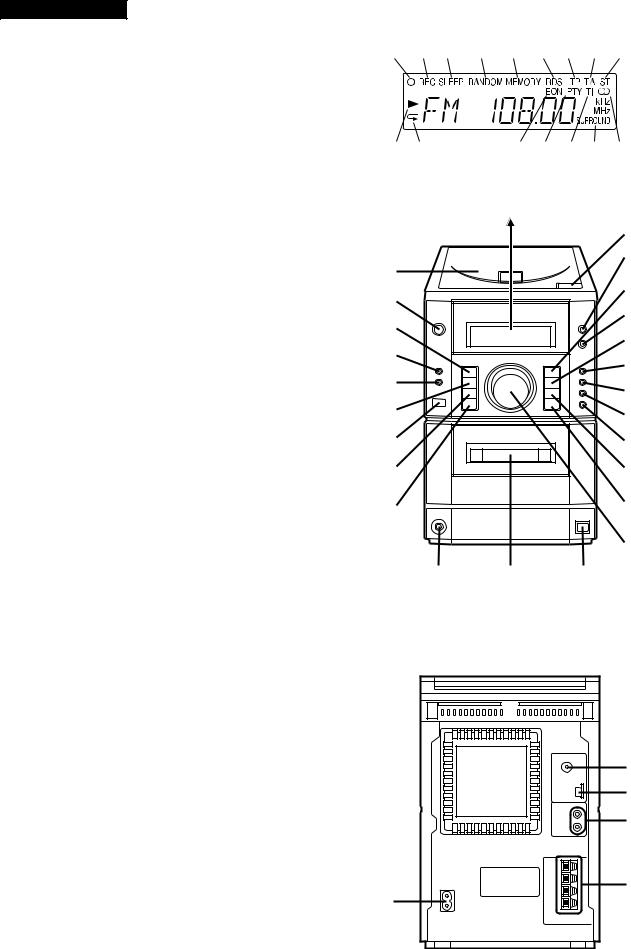
NAMES OF PARTS
XL-560H/E,570H/E
Illustration: XL-560H/570H
■ Front panel |
1 2 3 |
|
|
|
|
|||
1. |
Timer Indicator |
|
|
|
|
|||
2. |
Record Indicator |
|
|
|
|
|
|
|
3. |
Sleep Indicator |
|
|
|
|
|
|
|
4. |
(CD) Random Indicator |
|
|
|
|
|
|
|
5. |
(CD/TUNER) Memory Indicator |
|
|
|
|
|
|
|
6. |
RDS Indicator (XL-560H/570H Only) |
|
|
|
|
|
|
|
7. |
Traffic Programme Indicator (XL-560H/570H Only) |
10 11 |
|
|
|
|
|
|
8. |
Traffic Announcement Indicator (XL-560H/570H Only) |
|
|
|
|
|
|
|
9. |
FM Stereo Mode Indicator |
|
|
|
|
|
|
|
10. |
(CD) Play Indicator |
|
|
|
|
|
|
|
11. |
(CD) Repeat Indicator |
|
|
|
|
|
|
|
12. |
EON Indicator (XL-560H/570H Only) |
|
|
|
|
|
|
|
13. |
Programme Type Indicator (XL-560H/570H Only) |
|
|
|
|
|
|
|
14. |
Traffic Information Indicator (XL-560H/570H Only) |
|
|
|
|
|
|
|
15. |
Surround Indicator (XL-560H/570H Only) |
17 |
|
|
|
|
|
|
16. |
FM Stereo Indicator |
|
|
|
|
|
|
|
17. |
CD Compartment |
18 |
|
|
|
|
|
|
18. |
On/Stand-by Button |
|
|
|
|
|
|
|
19. |
Volume/Jog Dial Selector Button |
19 |
|
|
|
|
|
|
|
|
|
|
|
|
|
||
20. |
Record Pause/Beat Cancel Selector Button |
20 |
|
|
|
|
|
|
21. |
Clock/Timer/Sleep Button |
|
|
|
|
|
|
|
|
|
|
|
|
|
|
||
22. |
Function Selector Button |
21 |
|
|
|
|
|
|
23. |
Remote Control Sensor |
|
|
|
|
|
|
|
|
|
|
|
|
|
|
||
24. |
Band Selector Button |
22 |
|
|
|
|
|
|
25. |
Memory/Set Button |
|
|
|
|
|
|
|
|
|
|
|
|
|
|
||
26. |
CD Eject Button |
23 |
|
|
|
|
|
|
27. |
Bass/Treble Selector Button |
|
|
|
|
|
|
|
|
|
|
|
|
|
|
||
28. |
(CD) Play/Pause Button |
24 |
|
|
|
|
|
|
|
(TAPE) Play Button |
|
|
|
|
|
|
|
29. |
Surround Button (XL-560H/570H Only) |
|
|
|
|
|
|
|
30. |
(CD/TAPE) Stop Button |
25 |
|
|
|
|
|
|
|
(TUNER) Clear Button |
|
|
|
|
|
|
|
|
|
|
|
|
|
|
|
|
31. |
Programme Type/Traffic Information |
|
|
|
|
|
|
|
|
Search Button (XL-560H/570H Only) |
|
|
|
|
|
|
|
32. |
EON Button (XL-560H/570H Only) |
38 |
|
|
|
|
||
33. |
ASPM Button (XL-560H/570H Only) |
|
|
|
|
|||
34. |
Display Mode Selector Button (XL-560H/570H Only) |
|
|
|
|
|||
35. |
(CD) Cue Button |
|
|
|
|
|
|
|
|
(TAPE) Fast Forward Button |
|
|
|
|
|
|
|
|
(TUNER) Tuning Up Button |
|
|
|
|
|
|
|
36. |
(CD) Review Button |
|
|
|
|
|
|
|
|
(TAPE) Rewind Button |
|
|
|
|
|
|
|
|
(TUNER) Tuning Down Button |
|
|
|
|
|
|
|
37. |
Jog Dial |
|
|
|
|
|
|
|
38. |
Headphone Socket |
|
|
|
|
|
|
|
39. |
Cassette Compartment |
|
|
|
|
|
|
|
40. |
CD Digital Output Socket |
|
|
|
|
|
|
|
|
|
|
|
|
|
|
||
|
|
|
|
|
|
|
|
|
|
|
|
|
|
|
|
|
|
|
|
|
|
|
|
|
|
|
|
|
|
|
|
|
|
|
|
|
|
|
|
|
|
|
|
|
|
|
|
|
|
|
|
|
|
■ Rear panel
1. AC Power Input Socket
2. FM 75 ohms Aerial Socket
3. AM Loop Aerial Input Socket
4.Video/Auxiliary (Audio Signal) Input Sockets
5.Speaker Terminals
1
4 5 6 7 8 9
1213 141516
26
27
28
29
30
31
32
33
34
35
36
37
39 40
2
3
4
5
– 4 –
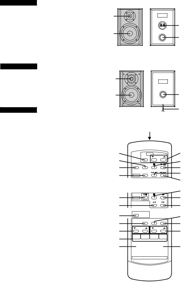
CP-XL570H
■Speaker section
1.Tweeter
2.Woofer
3.Speaker Terminals
4.Bass Reflex Ducts
CP-XL560H
1.Tweeter
2.Woofer
3.Bass Reflex Ducts
4.Speaker Wire
XL-560H/E,570H/E
■Remote control
1.Remote Control Transmitter LED
●Tuner control section
2.Programme Type/Traffic Information Search Button (XL-560H/570H Only)
3.Preset Up/Down Buttons
●CD control section
4.Clear Button
5.Random/Repeat Button
6.Memory Button
7.Stop Button
8.Play/Pause Button
9.Track Down/Review Button
10.Track Up/Cue Button
●Tape control section
11.Record Pause/Beat Cancel Selector Button
12.Rewind Button
13.Stop Button
14.Play Button
15.Fast Forward Button
●Common section
16.Surround Button (XL-560H/570H Only)
17.Sleep Button
18.Bass Up/Down Buttons
19.Function Selector Buttons
20.On/Stand-by Button
21.Timer Button
22.Clock Button
23.Treble Up/Down Buttons
24.Volume Up/Down Buttons
XL-560H/E,570H/E
1
3
2
4
1
2 |
3 |
4
Illustration: XL-560H/570H
1
2 |
3 |
4 |
7 |
5 |
8 |
6 |
9 |
|
10 |
11 |
13 |
14 |
|
12 |
15 |
16 |
21 |
17 |
22 |
18 |
23 |
19


20
 24
24
– 5 –

– 6 –
PREPARATION FOR USE |
RESETTING THE MICRO- |
■ Remote control |
COMPUTER |
|
0.2 m - 6 m (8" - 20")
15
15
1 3
3
 2,3
2,3
Notes concerning use:
●Replace the batteries if the operating distance is reduced or if the operation becomes erratic.
●Periodically clean the transmitter LED on the remote control and the sensor on the main unit with a soft cloth.
●Exposing the sensor on the main unit to strong light may interfere with operation. Change the lighting or the direction of the unit.
●Keep the remote control away from moisture, excessive heat, shock, and vibrations.
Reset the microcomputer under the following conditions:
●To erase all of the stored memory contents (clock and timer settings, and tuner and CD presets).
●If the display is not correct.
●If the operation is not correct.
1 Press the ON/STAND-BY button to enter the stand-by mode.
2 Unplug the AC power lead from the AC INPUT socket on this unit.
3 Whilst pressing down the MEMORY/SET button and the BASS/TREBLE button, plug the AC power lead into the AC INPUT socket on this unit.
Caution:
●The operation explained above will erase all data stored in memory, such as clock and timer settings, and tuner and CD presets.
SETTING THE CLOCK
(Main unit operation)
In this example, the clock is set for the 24-hour (0:00) system.
CLOCK/TIMER/  SLEEP
SLEEP 
MEMORY/
SET
Jog dial
2
3
0:00 
 AM 12:00
4
5
6
7
1 Press the CLOCK/TIMER/SLEEP button to enter the time check mode.
2 Within 3 seconds, press the MEMORY/SET button.
3 Turn the jog dial to select the time display mode. "0:00" → The 24-hour display will appear.
(0:00 - 23:59)
"AM 12:00" → The 12-hour display will appear. (AM 12:00 - PM 11:59)
● Note that this can only be set when the unit is first |
OPERATION |
installed or it has been reset. |
|
4 Press the MEMORY/SET button. |
|
5 Adjust the hour by turning the jog dial. |
|
● When the jog dial is turned one click clockwise, |
|
the time will increase by 1 hour. When it is turned |
|
one click anti-clockwise, the time will decrease by |
|
1 hour. |
|
Keep turning the jog dial to change the time con- |
|
tinuously. |
|
● When the 12-hour display is selected, "AM" will |
MANUAL |
change automatically to "PM". |
|
6 Press the MEMORY/SET button. |
|
7 Adjust the minutes by turning the jog dial. |
|
● When the jog dial is turned one click clockwise, |
|
the time will increase by 1 minute. When it is |
|
turned one click anti-clockwise, the time will de- |
|
crease by 1 minute. |
(FOR |
Keep turning the jog dial to change the time con- |
|
tinuously. |
|
● The hour setting will not advance even if minutes |
|
advance from "59" to "00". |
|
8 Press the MEMORY/SET button. |
-XL |
● The clock starts operating from "0" seconds. (Sec- |
|
onds are not displayed.) |
|
Note: |
560H/570H) |
● In the event of a power failure or when the AC |
|
power lead is disconnected, the clock display will |
|
go out. |
|
When the AC power supply is restored, the clock |
|
display will flash on and off to indicate the time |
|
when the power failure occurred or when the AC |
|
power lead was disconnected. |
|
If this happens, follow the procedure below to |
|
change the clock time. |
|
To change the clock time:
Perform steps 1, 2 and 5 - 8 above.
To change the time display mode:
560H/E,570H/E-XL
|
Perform steps 1 - 3 in the section "RESET- |
8 |
TING THE MICROCOMPUTER". |
Perform steps 1 - 8 above. |
– 7 –
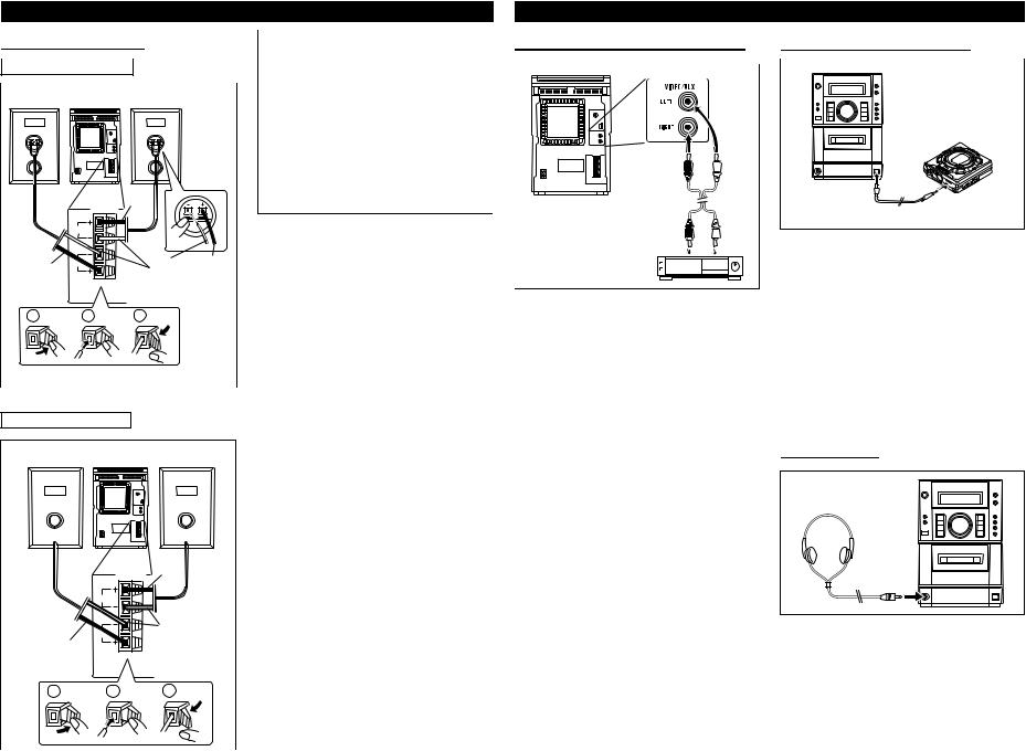
PREPARATION FOR USE
■ Speaker connection
In the case of XL-570H
Right speaker |
Left speaker |
Black
SPEAKERS
Black |
|
White |
Black |
|
line |
|
|
|
RATED SPEAKER IMPEDANCE: |
|
|
|
|
|
|
1 |
2 |
3 |
|
In the case of XL-560H
Right speaker |
Left speaker |
Black
SPEAKERS
|
|
White |
Black |
|
line |
|
|
|
|
RATED SPEAKER IMPEDANCE: |
|
1 |
2 |
3 |
●Unplug the AC power lead from the AC socket before connecting or disconnecting any component.
Caution for XL-570H:
●Before connecting the speakers to the unit, connect the speaker wires to the speakers fi rst . Th en , connect the speaker wire to the terminals on the unit.
●Connect the speakers to the main unit, and then use the system. If any of the speakers is not connected, the main unit or the speakers may malfunction or may be damaged.
Connect each speaker wire to the SPEAKER terminals as shown.
Use speakers with an impedance of 4 ohms or more.
Use of speakers with an impedance less than 4 ohms may damage your unit.
●Connect the wire with the white line to the minus (−) terminal and the plain wire to the plus (+) terminal.
Notes:
●Do not mix the right channel and left channel wiring when connecting the speakers to the unit.
●Do not let the bare speaker wires touch each other as this may damage the amplifier and/or speakers.
●Do not allow any objects to fall into or to be placed in the bass reflex ducts.
Caution:
●The speakers included with the unit should only be used with the XL-570H or XL-560H. Do not use them with other models. Do not connect the XL-570H's or XL-560H's speak terminals to any speakers other than those included with the unit.
USING EXTERNAL UNITS
■ VIDEO/AUX (Audio signal) input
External unit
To listen to or record signals from external sources through this unit:
1 Use an RCA lead to connect the desired external unit to the VIDEO/AUX sockets.
(red → right channel, white → left channel)
●When using video equipment (Laser Disc player, VCR), be sure to connect the audio output to this unit and the video output to a television.
2 Press the ON/STAND-BY button to turn the power on.
3 Press the FUNCTION button until "AUX" appears in the display.
4 Operate the external unit.
5 To record the sound from the external unit, perform steps 2 - 4 of the "Recording from the built-in radio" section.
Note:
●To prevent hum interference, do not place this unit near television receivers.
■ CD digital output (optical)
Commercially available digital cable
The CD digital signal from this unit can be recorded by other DAT or MiniDisc recorders.
1 Remove the DIGITAL OUT socket cover.
2 Use a commercially available digital cable to connect the unit to the OPTICAL IN socket of a MiniDisc recorder or a DAT.
3 Put the external unit in the recording mode.
4 Play a CD on this unit.
Note:
● Only CD signals can be output.
■ Headphones
●Before plugging in or unplugging the headphones, make sure the volume level is reduced.
●Be sure your headphones have a 3.5 mm (1/8") diameter plug and are between 16 ohms and 50 ohms impedance. The recommended impedance is 32 ohms.
●When headphones are connected, the speakers are disconnected automatically. Adjust the VOLUME control for desired volume.
560H/E,570H/E-XL
XL-560H/E,570H/E
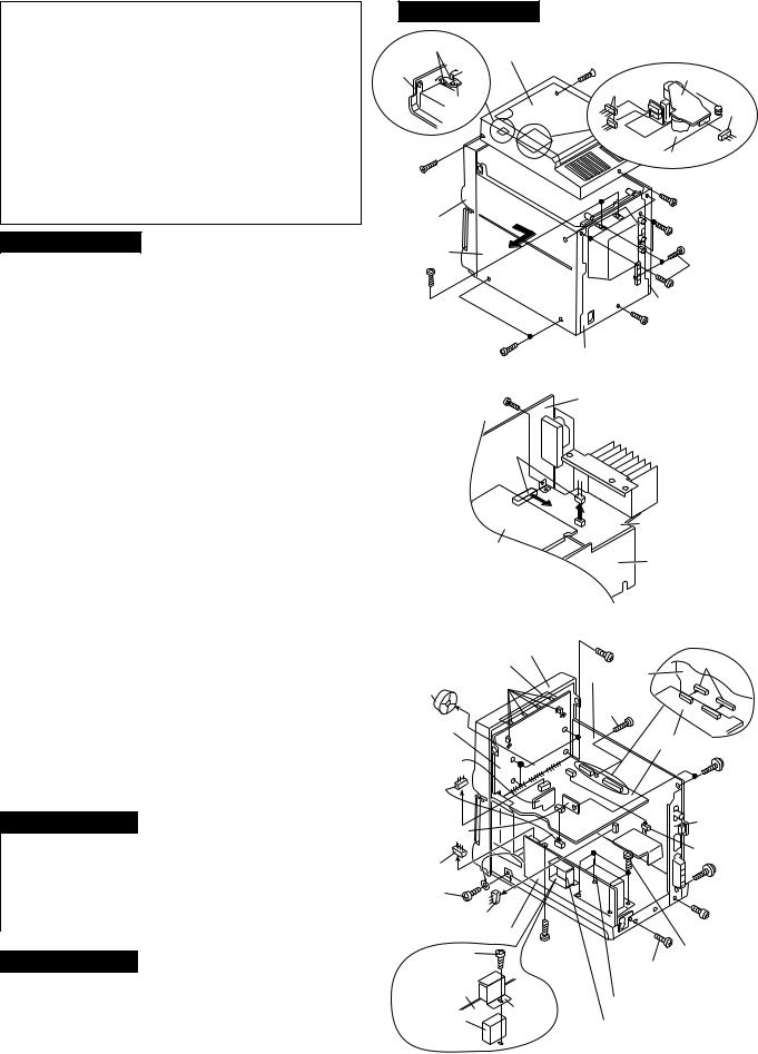
DISASSEMBLY
Caution on Disassembly
Follow the below-mentioned notes when disassembling the unit and reassembling it, to keep it safe and ensure excellent performance:
1.Take cassette tape and compact disc out of the unit.
2.Be sure to remove the power supply plug from the wall outlet before starting to disassemble the unit.
3.Take off nylon bands or wire holders where they need to be removed when disassembling the unit. After servicing the unit, be sure to rearrange the leads where they were before disassembling.
4.Take sufficient care on static electricity of integrated circuits and other circuits when servicing.
XL-560H/E,570H/E
STEP |
REMOVAL |
|
PROCEDURE |
|
FIGURE |
|
|
|
|
|
|
1 |
Side Panel |
1. |
Screw .................. |
(A1) x8 |
8-1 |
|
(Left/Right) |
|
|
|
|
|
|
|
|
|
|
2 |
Top Cabinet/ |
1. |
Screw .................. |
(B1) x1 |
8-1 |
|
Switch PWB |
2. |
Socket ................. |
(B2) x3 |
|
|
(Note) |
3. |
Hook .................... |
(B3) x2 |
|
|
|
|
|
|
|
3 |
Rear Panel |
1. |
Screw .................. |
(C1) x3 |
8-1 |
|
|
2. |
Screw .................. |
(C2) x2 |
|
4 |
Power Amp. PWB |
1. Screw .................. |
(D1) x1 |
8-2 |
|
|
|
2. |
Socket ................. |
(D2) x2 |
|
|
|
|
|
|
|
5 |
Main PWB/ |
1. |
Screw .................. |
(E1) x3 |
8-3 |
|
Headphones PWB |
2. |
Screw .................. |
(E2) x2 |
|
|
|
3. |
Bracket ................ |
(E3) x1 |
|
|
|
4. |
Socket ................. |
(E4) x3 |
|
|
|
|
|
|
|
6 |
Display PWB/ |
1. |
Screw .................. |
(F1) x4 |
8-3 |
|
CD Servo PWB/ |
2. |
Socket ................. |
(F2) x4 |
|
|
LED PWB |
3. |
Knob .................... |
(F3) x1 |
|
|
(With Switch PWB) |
4. |
Hook .................... |
(F4) x6 |
|
7 |
Front Panel |
1. |
Screw .................. |
(G1) x1 |
8-3 |
|
|
|
|
|
|
8 |
Power PWB |
1. |
Screw .................. |
(H1) x4 |
8-3 |
|
|
2. |
Screw .................. |
(H2) x1 |
|
|
|
3. |
Screw .................. |
(H3) x2 |
|
|
|
4. |
Bracket ................ |
(H4) x1 |
|
|
|
|
|
|
|
9 |
CD Digital PWB |
1. |
Screw .................. |
(J1) x1 |
9-1 |
|
|
2. |
Cover ................... |
(J2) x1 |
|
|
|
|
|
||
10 |
Tape Mechanism |
1. Open the cassette holder |
9-1 |
||
|
|
2. |
Screw .................. |
(K1) x4 |
|
|
|
|
|
|
|
11 |
CD Mechanism |
1. |
Screw .................. |
(L1) x3 |
9-2 |
|
|
|
|
|
|
Note:
After removing the connector for the optical pickup from the connector, wrap the conductive aluminium foil around the front end of connector to protect the optical pickup from electrostatic damage.
CP-XL560H
STEP |
REMOVAL |
|
PROCEDURE |
|
FIGURE |
|
|
|
|
|
|
1 |
Speaker |
1. Net ........................... |
(A1) x1 |
9-3 |
|
|
|
2. |
Front Panel ............. |
(A2) x1 |
|
|
|
3. |
Screw ...................... |
(A3) x4 |
|
|
|
4. |
Screw ...................... |
(A4) x2 |
|
|
|
5. |
Holder ..................... |
(A5) x1 |
|
|
|
|
|
|
|
CP-XL570H
STEP |
REMOVAL |
|
PROCEDURE |
|
FIGURE |
|
|
|
|
|
|
1 |
Speaker |
1. Net ........................... |
(A1) x1 |
9-4 |
|
|
|
2. |
Screw ...................... |
(A2) x4 |
|
|
|
3. |
Ring ......................... |
(A3) x1 |
|
|
|
4. |
Screw ...................... |
(A4) x4 |
|
|
|
|
|
|
|
XL-560H/E,570H/E
(B3)x2 |
Top Cabinet |
(A1)x1 |
Top |
|
ø3x10mm |
Cabinet |
|
CD Motor PWB |
|
|
|
|
Swicth |
(B2)x2 |
|
(B2)x1 |
|
|
PWB |
|
|
|
CD Mechanism |
(A1)x1 |
|
(B1)x1 |
ø3x10mm |
|
ø3x10mm |
Front |
|
(C1)x2 |
Panel |
|
|
|
ø3x10mm |
|
|
|
|
Side Panel |
|
(A1)x4 |
(Right) |
|
|
|
|
ø3x10mm |
(C2)x2 |
|
Side Panel |
ø3x8mm |
|
|
|
(Lift) |
|
|
(A1)x2 |
|
|
(C1)x1 |
|
|
ø3x10mm |
|
|
ø3x10mm |
|
|
|
RearPanel |
|
Figure 8-1 |
|
|
(D1)x1 |
Main PWB |
|
ø3x8mm |
|
|
(D2)x2 |
|
Power Amp.
PWB
CD Servo
PWB Power
PWB
|
Figure 8-2 |
||
|
|
(F1)x4 |
|
Front Panel |
ø2.5x10mm |
||
LED PWB |
|
(E4)x2 |
|
(F4)x6 |
|
Main PWB |
|
|
|
||
(F3)x1 |
|
(E2)x1 |
|
Display PWB |
|
ø3x8mm |
|
|
|
||
Tape |
|
CD Servo |
|
Mechanism |
|
PWB |
|
PWB |
|
(E1)x2 |
|
(F2)x2 |
|
||
|
ø3x10mm |
||
|
|
||
Headphones |
|
(E3)x1 |
|
|
|
||
PWB |
|
(F2)x1 |
|
|
|
||
(F2)x1 |
|
|
|
(H3)x1 |
|
(E1)x1 |
|
|
ø3x10mm |
||
ø3x6mm |
|
||
|
|
||
(E4)x1 |
|
(E2)x1 |
|
Power PWB |
|||
ø3x8mm |
|||
|
(G1)x1 |
||
(H3)x1 |
(H1)x4 |
||
ø3x6mm |
ø3x8mm |
(H2)x1 ø4x6mm |
|
Power PWB |
|
ø3x10mm |
|
|
|
||
Sub Power |
(H4)x1 |
Main Power Transformer |
|
Sub Power Transformer |
|||
Transformer |
|||
Figure 8-3
– 8 –

XL-560H/E,570H/E
Front Panel |
|
Cassette |
|
Holder |
Tape |
|
|
Open |
Mechanism |
|
|
(J2)x1 |
|
|
(K1)x4 |
PWB |
ø2.5x10mm |
|
|
Holder |
(J1)x1 |
CD Digital |
|
PWB |
ø2.5x10mm |
Figure 9-1
(L1)x3
ø2.5x10mm
PWB Washer x3
CD Mechanism
Top Cabinet
Figure 9-2
CP-XL560H |
Speaker Box |
|
|
Tweeter
(A2)x1 (A5)x1 (A4)x2
ø3x12mm
(A1)x1
(A3)x4
ø4x20mm
Figure 9-3
CP-XL570H
Tweeter
(A4)x4
ø3x12mm
(A1)x1
Woofer
(A3)x1
(A2)x4
ø4x16mm
Figure 9-4
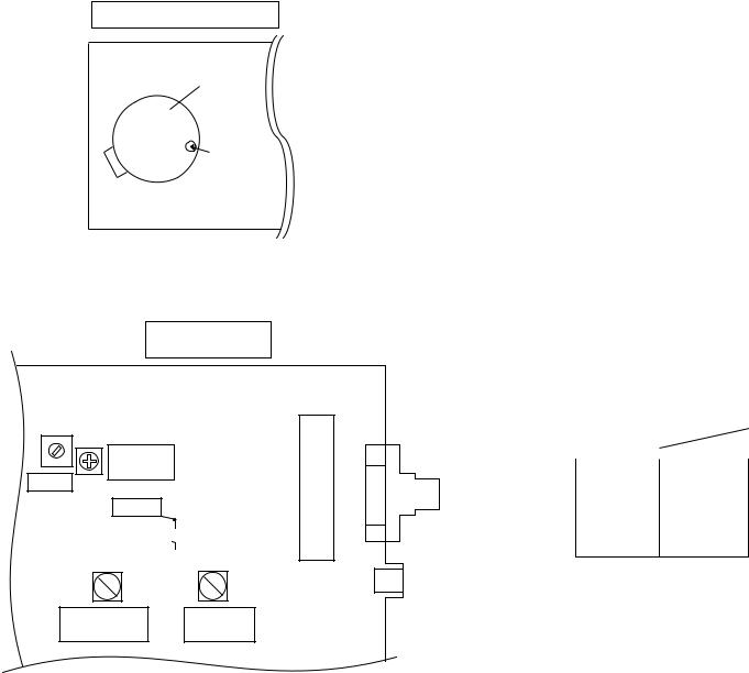
REMOVING AND REINSTALLING THE MAIN PARTS
Woofer
Speaker Box
CD MECHANISM SECTION
Perform steps 1 to 6 and 11 of the disassembly method to remove the CD mechanism.
How to remove the pickup (See Fig. 9-5)
1.Remove the mechanism cover, paying attention to the pawls (A1) x 4 pcs.
2.Remove the screws (A2) x 2 pcs., to remove the shaft (A3) x 1 pc.
3.Remove the stop washer (A4) x 1 pc., to remove the gear (A5) x 1 pc.
4.Remove the pickup.
Note:
After removing the connector for the optical pickup from the connector, wrap the conductive aluminium foil around the front end of connector to protect the optical pickup from electrostatic damage.
Mechanism Cover
(A1) x2
(A1) x2
(A2) x2 ø2.6 x6mm
CD Mechanism
Shaft (A3) x1
StopWasher (A4) x1
Gear (A5) x1
Pickup Unit
Figure 9-5
– 9 –
XL-560H/E,570H/E
ADJUSTMENT
MECHANISM SECTION
• Driving Force Check
Torque Meter |
Specified Value |
|
|
Play: TW-2412 |
Over 80 g |
|
|
• Torque Check
Torque Meter |
Specified Value |
|
|
Play: TW-2111 |
30 to 60 g. cm |
|
|
Fast forward: TW-2231 |
55 to 140 g.cm |
|
|
Rewind: TW-2231 |
55 to 140 g.cm |
|
|
• Tape Speed
Test Tape |
Adjusting |
Specified |
Instrument |
|
Point |
Value |
Connection |
|
|
|
|
MTT-111 |
Motor |
3,000 ± |
Headphone |
|
(M901) |
90 Hz |
terminal |
TAPE MECHANISM
M901
Tape
Motor
Variable resistor
Figure 10-1 ADJUSTMENT POINT
MAIN PWB
FE301
T351
VR351
FM Mute
Level
AM IF
TP301
R336
T306 T302
AM Band |
AM |
Coverage fL |
Tracking |
TUNER SECTION
fL: Low-range frequency fH: High-renge frequency
• AM IF/RF
Signal generator: 400 Hz, 30%, AM modulated
Test Stage |
Frequency |
Frequency |
Setting/ |
Instrument |
|
|
Display |
Adjusting |
Connection |
|
|
|
Parts |
|
IF |
450 kHz |
1,620 kHz |
T351 |
*1 |
|
|
|
|
|
AM Band |
— |
522 kHz |
(fL): T306 |
*2 |
Coverage |
|
|
1.1 ± 0.1 V |
|
|
|
|
|
|
AM |
990 kHz |
990 kHz |
T302 |
*1 |
Tracking |
|
|
|
|
|
|
|
|
|
*1. |
Input: Antenna, Output: Speaker Terminal |
*2. |
Input: Input is not connected, Output: TP301 |
• FM Mute Level |
|
Signal generator: 1 kHz, 40 kHz dev., FM modulated |
|
Frequency |
Display |
Adjusting |
Instrument |
|
|
Parts |
Connection |
|
|
|
|
98.00 MHz |
98.00 MHz |
VR351*1 |
Input: SO301 |
(25 dBμV) |
|
|
Output: Speaker |
[For U.K.] |
|
|
Terminal |
(30 dBμV) |
|
|
|
[For Europe] |
|
|
|
|
|
|
|
*1. Adjust so that an output signal appears.
• Check FM VT
Signal generator: 1 kHz, 40 kHz dev., FM modulated
Frequency |
Display |
Check Point |
Instrument |
|
|
|
Connection |
|
|
|
|
87.5 MHz |
87.5 MHz |
2.2 V ± 0.7 V |
TP301 |
|
|
|
|
108 MHz |
108 MHz |
7.3 V ± 1.0 V |
TP301 |
• Setting the Test Mode
Keeping the FF/FWD button and MEMORY/SET button pressed, turn on POWER. Then, the frequency is initially set in the memory as shown in Table. Call it with the JOG DIAL knob to use it for adjustment and check of tuner circuit.
Preset No. |
FM STEREO |
Preset No. |
AM |
|
|
|
|
|
|
1 |
87.50 |
MHz |
6 |
522 kHz |
2 |
108.00 |
MHz |
7 |
1,620 kHz |
3 |
98.00 |
MHz |
8 |
990 kHz |
4 |
90.00 |
MHz |
9 |
603 kHz |
5 |
106.00 |
MHz |
10 |
1,404 kHz |
|
|
|
|
|
|
Preset No. |
BAND |
||
|
|
|
|
|
|
11~25 |
|
|
|
|
|
|
||
|
|
|
||
SO301 |
Preset No. |
FM MONO |
||
|
|
|
||
26 |
106.00 |
MHz |
||
FM |
||||
ANTENNA |
27 |
90.00 |
MHz |
|
SOCKET |
28 |
98.00 |
MHz |
|
|
29 |
108.00 |
MHz |
|
|
30 |
87.50 |
MHz |
|
CNP301
AM
ANTENNA
SOCKET
Figure 10-2 ADJUSTMENT POINTS
– 10 –
XL-560H/E,570H/E
RDS (RDS circuit is only for XL-560H/570H)
In order to receive RDS broadcasts, adjust the preset variable resistor as follows.
Adjust the center frequency of the 57 kHz BPF (band-pass filter) using the variable resistor (VR521).
Receiver: Connect the SG output to the aerial terminal.
It is not necessary to connect the speaker output terminal.
Set the frequency display to 98 MHz to tune in the 98 MHz frequency.
C525
0.022
|
|
6 |
|
|
0.022 |
|
input |
|
|
50mV |
|
|
|
|
|
|
|
Frequency |
|
57kHz |
|
counter |
|
|
|
Adjust the 57 kHz |
|
|
|
||
oscillator |
|
|
|
|
|
oscillator before |
|
|
|
|
|
|
|
|
starting, so that |
|
|
|
the frequency |
|
|
|
counter reads |
|
|
|
57kHz ± 6Hz |
IC521
RDS DECODER
LA2232
5 |
B.P.F |
11 |
C524 |
T.P |
VR521 |
0.01 |
||
|
|
4.7k |
R521
1k
Electric
Voltmeter
Procedure
Apply 57 kHz, 50mV(ms) to pin (6) of the input on LA2232.
Adjust the variable resistor (VR521) until you have the maximun value on the electric voltmeter.
Adjustment point
Done
R523
6.8k
RDS (Radio Data System) OPERATION
RDS is a broadcasting service which a growing number of FM stations are now providing. It allows these FM stations to send additional signals along with their regular programme signals. For example, the stations send their station names, and information about what type of programme they broadcast, such as sports or music, etc.
When tuned to an FM station providing the RDS service, RDS will appear, the station frequency (and then the station name if sent) will be displayed.
The TP (Traffic Programme) will appear on the display when the received broadcast carries traffic announcements, and the TA (Traffic Announcem ent) will appear whilst a traffic announcement is being received.
EON will appear whilst the EON (Enhanced Other Networks information) data is being broadcast.
Note:
When the TP and TA appear at the same time, an announcement is being made.
When only the TA appears, an announcement is not being made. (See page 21.)
■ Information Provided by RDS
With the XL-570H/XL-560H, you can display two types of RDS service. To show them in the display, press the DISPLAY MODE button.
Each time you press the DISPLAY MODE button, the display will change to show the following information.
|
|
Station names commonly |
|
PS (Programm e |
|||
known will be displayed. |
|||
Service): |
"NO PS" appears if no sig- |
||
|
|
nal is being received. |
|
|
|
||
|
|
Programme type will be dis- |
|
PTY (Programme |
|||
Type): |
played. |
||
"NO PTY" appears if no sig- |
|||
|
|
nal is being received. |
|
|
|
|
|
Station Frequency: |
Station frequencies. |
||
|
|
|
|
|
|
|
|
Descriptions of the PTY (Programme Type) codes, TP (Traffic Programme) and TA (Traffic Announcement)
With the XL-570H/XL-560H, you can search for and receive the following PTY, TP and TA signals.
NEWS: Short accounts of facts, events and publicly expressed views, reportage and actuality.
AFFAIRS: Topical programme expanding or enlarging upon the news, generally in different presentation style or concept, including debate, or analysis.
INFO: Programmes whose purpose is to impart advice in the widest sense.
SPORT: Programme concerned with any aspect of sport.
EDUCATE: Programme intended primarily to educate, of which the formal element is fundamental.
DRAMA: All radio plays and serials.
CULTURE: Programmes concerned with any aspect of national or regional culture, including language, theatre, etc.
SCIENCE: Programmes about the natural sciences and technology.
VARIED: Used for mainly speech-based programmes usually of light-en- tertainment nature, not covered by other categories. Examples include: quizzes, panel games, personality interviews.
POP M: Commercial music, which would generally be considered to be of current popular appeal, often featuring in current or recent record sales charts.
ROCK M: Contemporary modern music, usually written and performed by young musicians.
DISPLAY
EASY M: Current contemporary music con-
MODE sidered to be "easy-listening", as opposed to Pop, Rock or Classical, or one of the specialised music styles, Jazz, Folk or Country, Music in this category is often but not always, vocal, and usually of short duration.
(Continued)
LIGHT M: Classical Musical for general, rather than specialist appreciation. Examples of music in this category are instrumental music, and vocal or choral works.
CLASSICS: Performances of major orchestral works, symphonies, chamber music etc., and including Grand Opera.
OTHER M: Musical styles not fitting into any of the other categories. Particularly used for specialist music of which Rhythm & Blues and Reggae are examples.
WEATHER: Weather reports and forecasts and Meteorological information.
FINANCE: Stock Market reports, commerce, trading etc.
CHILDREN: For programmes targeted at a young audience, primarily for entertainment and interest, rather than where the objective is to educate.
SOCIAL: Programmes about people and things that influence them individually or in groups, Includes: sociolog y, his tory, ge ography, psychology and society.
RELIGION: Any aspect of beliefs and faiths, involving a God or Gods, the nature of existence and ethics.
PHONE IN: Involving members of the public expressing their views either by phone or at a public forum.
TRAVEL: Features and programmes concerned with travel to near and far destinations, package tours and travel ideas and opportunities. Not for use for Announcements about problems, delays, or roadworks affecting immediate travel where TP/TA should be used.
LEISURE: Programmes concerned with recreational activities in which the listener might participate. Examples include, Gardening, Fishing, Antique collecting, Cooking, Food & Wine etc.
JAZZ: Polyphonic, syncopated music characterised by improvisation.
COUNTRY: Songs which originate from, or continue the musical tradition of the American Southern States. Characterised by a straightforward melody and narrative story line.
NATION M: Current Popular Music of the Nation or Region in that country's language, as opposed to international `Pop' which is usually US or UK inspired and in English.
OLDIES: Music from the so-called "golden age" of popular music.
FOLK M: Music which has its roots in the musical culture of a particular nation, usually played on acoustic instruments. The narrative or story may be based on historical events or the people.
DOCUMENT: Programme concerned with factual matters, presented in an investigative style.
TEST: Broadcast when testing emergency broadcast equipment or receivers.
ALARM: Emergency announcement made under exceptional circumstances to give warning of events causing danger of a general nature.
NONE: No programme type (receive only)
TP: Broadcasts which carry traffic announcements
TA: Traffic announcements are being broadcast at present.
Note:
●When the unit is in the EON stand-by mode and a programme is selected, the unit will display "TI" instead of "TP" or "TA".
– 11 –
XL-560H/E,570H/E
TEST MODE
The test mode applied to this microcomputer has three modes, namely ordinary test mode to be used for adjustment or measurement, aging test mode to be used for aging test, and self-diagnosis test mode for self-inspection in case of final product inspection.
The test mode specification prescribes the microcomputer with RDS (RH-IX0014SJZZ Serial No. 904xxxxx) and the microcomputer with RDS (RH-IX0021SJZZ Serial No. 905xxxxx~ ).
1. Turning on the test mode
To turn on the specific test mode, press the POWER button, holding down the following two buttons in the ordinary stand-by mode (power off state). In this case only the main unit button is valid. Even when the POWER of remote control button is set to on, the test mode is not turned on.
[Ordinary test mode]
1.CD Test Mode (TEST 1)………………………… BASS/TREBLE + PLAY
2.Tuner Test Mode (TEST 2)……………………… FF/FWD + MEMORY/SET
3.Electronic volume Test Mode (TEST 3)………… STOP + BASS/TREBLE
4.Timer Test Mode (TEST 4)……………………… FF/FWD + BAND
5.LCD Test Mode (TEST 5)………………………… MEMORY/SET + REW/REV
[Self-diagnosis Test Mode]
1. Button input diagnosis test mode (TEST6).……… FF/FWD + REC PAUSE
(RDS circuit is only for XL-560H/570H)
*Only for this mode four turning-on buttons are …… FUNCTION + RDS PTY-TI provided. The differ insignificantly in processing
after turning-on.
For the microcomputer without RDS, there are two turning-on buttons, since the two buttons (using the RDS buttons) are not provided.
– 12 –
XL-560H/E,570H/E
2. CD Test Mode (TEST 1)
In the CD test mode the operation of each step is enabled even when the LID-SW is off. However, if focus cannot be set in step 3 or any error processing is started, it is impossible to proceed to the next step. When the error processing is started, operations other than termination of test mode by pressing the POWER button or return to the step 1 by pressing the STOP button are inhibited.
1. Step 1 Mode
When the CD test mode is turned on, the following indication lights, the processing (until turning-off of CD STB terminal of CD initialization operation flow) is executed, and the next button input is waited.
After lighting for one second
If the following operation buttons are pressed in this state, the operation is performed as follows.
"POWER" ................. |
The test mode is turned off, the power is turned off, and the ordinary standby mode is set. |
"FF/FWD" ................. |
After the pickup returns once to the innermost periphery, it slides toward the outer periphery while this |
|
button is held down. |
"REW/REV" .............. |
After the pickup returns once to the innermost periphery, it slides toward the inner periphery while this |
|
button is pressed. However, if PU-IN is on, input is invalid. |
"PLAY" ..................... |
Shift to step 2 |
"STOP" ..................... |
Invalid |
"REC PAUSE" .......... |
Shift to step 5 |
*In case of initialization the pickup is moved toward the inner periphery. Any buttons other than "POWER" button are not accepted until the shift of pickup to the inner periphery is completed at this time. If PU-IN SW ON cannot be detected within 10 seconds, the slide motor is stopped, and the following error indication appears. Press the POWER button to end the test mode, or press the STOP button to return to step 1. Any other operations are inhibited.
2. Step 2 Mode
When the "PLAY" button is pressed in this mode, the laser lighting command LDON (8400) is sent, and the laser is turned on. Other operations are not performed.
If the following buttons are pressed in this state, the operation is performed as follows.
"POWER" ................ |
The test mode is turned off, the power is turned off, and the ordinary standby mode is set. |
"FF/FWD" ................ |
The pickup slides toward the outer periphery while this button is held down. |
"REW/REV" ............. |
The pickup slides toward the inner periphery while this button is held down. However, if PU-IN is on, input |
|
is invalid. |
"PLAY" ..................... |
Shift to step 3 |
"STOP" .................... |
Return to step 1 |
"REC PAUSE" ......... |
Shift to step 5 |
– 13 –
XL-560H/E,570H/E
3.Step 3 Mode
The laser is kept lighting. The processing (until turning-on of CLV servo of CD initialization operation flow) is executed, and the next button input is waited. (The focus servo is turned on, and focus search is performed.)
The focus search is repeated until the focus is set.
When the following operation buttons are pressed in this state, the operation is executed as follows.
"POWER" ................ |
The test mode is turned off, the power is turned off, and the ordinary standby mode is set. |
"FF/FWD" ................ |
The pickup slides toward the outer periphery while this button is held down. |
"REW/REV" ............. |
The pickup slides toward the inner periphery while this button is held down. However, if PU-IN is on, input |
|
is invalid. |
"PLAY" ..................... |
If the focus has been set, shift to step 4 is executed. If the focus has not been set, acceptance is inhibited. |
"STOP" .................... |
Return to step 1 |
"REC PAUSE" ......... |
Shift to step 5 |
*If the focus is disturbed after it has been set, the process returns to step 1.
4.Step 4 Mode
The CLV servo ON command (8600) sending operation is performed, and the next button input is waited. (The disc is rotated to perform CLV locking.)
The time display indicates always "0:00".
When the following buttons are pressed in this state, the operation is executed as follows.
"POWER" ................ |
The test mode is turned off, the power is turned off, and the ordinary standby mode is set. |
"FF/FWD" ................ |
The pickup slides toward the outer periphery while this button is held down. |
"REW/REV" ............. |
The pickup slides toward the inner periphery while this button is held down. However, if PU-IN is on, input |
|
is invalid. |
"PLAY" ..................... |
Shift to step 5 |
"STOP" .................... |
Return to step 1 |
"REC PAUSE" ......... |
Shift to step 5 |
*If the focus is disturbed, the process returns to step 1.
5.Step 5 Mode
The CD initialization operation flow is executed to the end, the mute is set to off, and playback is started. Even when the playback reaches the outermost periphery of disc, the operation does not stop. The LCD display indicates the playback past time as in case of ordinary CD playback.
When the following operation buttons are pressed in this sate, the operation is executed as follows.
"POWER" ................. |
The test mode is turned off, the power is turned off, and the ordinary standby mode is set. |
"FF/FWD" ................. |
The pickup slides toward the outer periphery while this button is held down. |
"REW/REV" .............. |
The pickup slides toward the inner periphery while this button is held down. However, if PU-IN is on, input |
|
is invalid. |
"PLAY" ..................... |
Invalid |
"STOP" ..................... |
Return to step 1 |
"FUNCTION" ............ |
Shift to step 6 |
"BAND" .................... |
Shift to step 7 |
*If the focus is disturbed, the process returns to step 1.
Other cautions
•TOC IL is not executed in the test mode.
•As for button operations other than those shown above, only the sound volume operation (with JOG) is accepted.
–14 –

XL-560H/E,570H/E
3.Tuner Test Mode (TEST 2)
1.Outline of tuner (radio) test mode
The tuner test mode is intended to store the adjustment and measurement frequencies in the preset memory CH without frequency setting by adjusting personnel when the tuner section is adjusted in the production line.
2.Details of tuner test mode
When the power is turned on by using the "POWER" button while the "FF/FWD" and "MEMORY/SET" buttons are held down in POWER OFF state, the frequency for adjustment and measurement of destination specified by the AREA terminal is preset and stored in the preset memory CH. However, Ordinary 1 and Ordinary 2 are set to the designation (destination selected by SPAN switching operation) set when the test mode is set. (As for frequencies to be preset and stored for each destination, refer to item 3.)
The tuner test mode is started from preset No.1.
The operations of test mode are identical with the ordinary operations of TUNER function. However, FUNCTION switching is invalid.
Since it is necessary to discard the content of preset memory when the tuner test mode is ended, "0000" or "1111" bits are written in the memory to be checked in case of memory check (in case of initial setting) so that memory abnormality is detected in case of initial setting so as to ensure memory initialization.
When the tuner test mode is turned on, the following indication lights for one second.
• The TUNER TEST2 mode is set as a result of >> + MEMORY + POWER. -> IF AC is set to OFF in the TEST2 mode, the initial state is restored.
When POWER is set to OFF, the memory of TEST2 mode is protected.
When the power is turned on again, the ordinary operation is enabled while the data is stored in the memory (besides TUNER).
If AC OFF state is maintained in this state for about 1/2 day, start is executed in the initial state.
• To clear the whole memory, insert the AC cord, holding down MEMORY + BASS/TREBLE.
3. Preset frequencies for various destinations (random preset memory)
CH |
BAND |
Europe 2, 4 |
|
|
|
1 |
|
FM 87.50 MHz |
2 |
|
FM108.00 MHz |
3 |
FM STEREO |
FM 98.00 MHz |
4 |
|
FM 90.00 MHz |
5 |
|
FM106.00 MHz |
|
|
|
6 |
|
AM 522 kHz |
7 |
|
AM1620 kHz |
8 |
AM |
AM 990 kHz |
9 |
|
AM 603 kHz |
10 |
|
AM1404 kHz |
|
|
|
11 |
|
|
12 |
|
|
13 |
LW |
|
14 |
|
|
15 |
|
|
|
|
|
CH |
BAND |
Europe 2, 4 |
|
|
|
16 |
|
|
17 |
|
|
18 |
|
|
19 |
|
|
20 |
|
|
|
|
|
21 |
|
|
22 |
|
|
23 |
|
|
24 |
|
|
25 |
|
|
|
|
|
26 |
|
FM106.00 MHz |
27 |
|
FM 90.00 MHz |
28 |
FM MONO |
FM 98.00 MHz |
29 |
|
FM108.00 MHz |
30 |
|
FM 87.50 MHz |
|
|
|
• The hatched sections of the table are not stored in memory.
– 15 –
XL-560H/E,570H/E
4.ASPM TEST Mode (RDS circuit is only for XL-560H/570H)
When the ASPM button is pressed, the test mode is set. It starts up at FM 106.50 MHz. (ST mode)
Data of 27 CH of 04 to 30 CH are all stored at FM 87.50 MHz (ST).
01 to 03CH are kept empty (If data of 3 CH are stored, max. 30 CH is filled.)
When the ASPM button is operated in the TEST mode 3, the preset data is cleared (overwrite).
A) Operation with ASPM button
Press the "ASPM" button or hold it down. (Any button other than ASPM button cancels the ASPM test mode.)
FM 105.00 MHz (ST) is indicated, and scan is started. (Start from 105.00 MHz)
During scanning the frequency is indicated.
When the ASPM button is pressed once in the TUNER TEST mode, the indication FM 106.50 MHz (ST) appears, and data of 04 to 30 CH are stored at 87.50 MHz (ST). When the ASPM button is operated again, the ASPM test operation mode is set.
End at FM 108.00 MHz (ST)
Only the number of preset and stored stations (number of CHs: max. 3 stations) is indicated for one second in the ASPM test mode. When two stations are stored, "_2 MEMORY" is indicated (lighted)for one second.
("02 MEMORY" indication is not given.)
"END" is not indicated
|
|
|
Not in zero-memory state |
|
|
|
|
|
(An example) |
01CH indication (for one second) |
FM P-01 |
|||
|
|
|
||
Frequency |
|
indication (for one second) |
FM 105.50MHz(ST) |
|
|
||||
|
|
|||
|
|
|
||
02CH indication (for one second) |
FM P-02 |
|||
In case of "_0 MEMORY" the process ends, and the FM 106.50 MHz (ST) state is resumed.
Confirmation of content of memory (Examples of concrete indication)
Frequency indication (for one second) |
FM 106.50MHz(ST) |
||
|
|
|
|
|
|
|
|
|
|
|
|
03CH indication (for one second) |
FM P-03 |
||
|
|
||
Frequency |
|
indication (for one second) |
FM 107.50MHz(ST) |
|
|||
|
|
|
|
|
|
|
|
|
|
|
|
After indication of continuous time series for one second the indication of FM 106.50 MHz (ST) is restored.
(The preset button is not pressed. The time series is indicated automatically, and the content of memory is indicated.)
*PS name is not indicated (while the content of memory is checked)
*If only 1 CH data is stored, FM P-01 -> FM 106.00 MHz -> FM 106.50 MHz (ST)
(An example) |
(1 sec) |
(1 sec) (ST) |
End indication |
– 16 –
XL-560H/E,570H/E
* When the "PRESET UP" button or "PRESET DOWN" button is pressed after completion, the following indication appears.
CH indication |
|
Frequency indication |
|
Time series indication of PS name indication is enabled. |
|
|
|||
(for 2 seconds) |
(for 2 seconds) |
|
(The same as in case of Ordinary) |
|
NO PS 
(Blinking for 5 seconds: 1 Hz)
Note: If PS is fixed after the frequency indication is resumed, the PS name indication is restored.
* If signal exists at 106.50 MHz, the following indication appears.
FM 106.50 MHz  PS name
NO PS  (Blinking for 5 seconds: 1 Hz)
When the PS data is given in case of NO PS indication, the PS name indication is restored.
Note: If PS is fixed after the frequency indication is resumed, the PS name indication is restored.
In case of memory storage with ASPM, for example, if RDS station 107.50 MHz has the PI code (the same as that of RDS station 105.50 MHz) and VSM is greater than 105.50 MHz (PR-01), data is overwritten on 105.5 MHz which is contained in "PR-01". (Frequency is changed to 107.50 MHz.)
If VSM is equal, previously stored 105.50 MHz remains.
When RDS station is stored in the test mode, the 2-second blinking of preset No. is not performed so as to save the production line test time. ("RDS" lighting is performed.)
Note: RDS operation is performed in FM MONO state. However, in case of ASPM, ASPM scan is performed after BAND is changed from FM MONO to FM STEREO.
Note: When the 
 (PLAY) button is pressed in TEST 2 mode, it is possible to check the sate of IF count. However, this function is for designer. It is not necessary for other sections.
– 17 –

XL-560H/E,570H/E
B) Cautions concerning the ASPM test mode
a)Cancel: When the "ASPM" button is pressed again during operation after it was first pressed in the test mode, the ASPM test mode is canceled (interrupted), and the initial state FM 106.50 MHz (ST) indication is restored.
(To check the data which was preset and stored until interruption, use the preset UP/DOWN button. (JOG UP/DOWN is
also available after JOG mode button operation.) wing indication appears.
b)The ASPM test mode is started in FM stereo state (FM 106.50 MHz ST). If any button other than ASPM button is pressed even only once after it is started, it becomes invalid, and the ASPM test mode becomes inoperable.
Invalid: The Ordinary mode is set while 4 to 30CH data remain in memory (or 1 to 30 CH MAX data remain in memory).
The "ASPM" button can be repeatedly operated until 01CH to 03CH is filled (up to 3 stations in memory). The number of stored stations -> Channel No. -> Frequency -> FM 106.50 MHz (ST) is indicated.
(1 second) (1 second) (1 second) (Initial state)
Up to 3 stations (1 to 3CH) can be indicated. This indication is given only in the ASPM test mode. In other mode (not in ASPM test mode) the number of stored stations -> END is indicated
c)Broadcast (without PI code) which is not RDS is not preset and stored in memory.
When the ASPM mode is set, the "MEMORY/SET" button cannot be operated (the test mode is canceled). Operation is possible after ASPM test mode operation.
d)Scan frequency: 105.00 MHz -> 108.00 MHz
Data are stored in memory so that the PI code is not duplicated (by seeing the PI code and VSM (S meter value). When the PI code is duplicated, both VSM (S meter value) are compared. The greater one is stored in memory but the smaller one is discarded.
For the stations having the same PI code, only one station having the highest electric field intensity is stored, and the memory is refilled. The channels which can be preset in the ASPM test mode are 01 to 03CH. If 3 stations are stored, 30 CH are filled.
For the stations having the same electric field intensity, the former (preceding station) is stored.
e)Signal of already stored same frequency is not stored. (The previously stored data is kept.)
f)The order of preset memory is 01CH -> 02CH -> 03CH.
g)When 01 to 03CH were all used, scan is aborted at the frequency at which filling occurred, and the following indication appears.
Number of stored stations -> Indication of stored channel -> Indication of frequency -> Return to initial FM 106.50 MHz (ST) (1 second) (1 second) (1 second)
In this period up to 3 stations are continuously indicated (1 to 3 CH).
h)If even one station could not be preset and stored in the APMS mode, "_0MEMORY" is indicated after scanning, and then FM 106.50 MHz (ST) indication is restored. (The first digit is space.)
("_0MEMORY" is indicated in the test mode.)
i)When the "ASPM" button is pressed after three stations are stored (after full-memory of 30 stations), "ASPM" blinks for 2 seconds, and then FM 106.50 MHz (ST) indication is restored without ASPM scanning. (RDS automatic lighting)
(In case of ASPM button operation in full memory state)
j)After completion of specific operation FM 106.50 MHz (ST) indication is restored.
k)Test mode
Use of only the function button is inhibited.
l)The first channel to be called (when data is stored in the ASPM mode) is 01CH.
m)After start-up in the ASPM test mode the ASPM key is valid even when it is pressed many times. The test mode is kept. If three stations are stored (1 to 3CH), full-memory state occurs.
If the ASPM button is pressed after occurrence of full-memory state, the same operation as that described in item i) is performed.
–18 –
XL-560H/E,570H/E
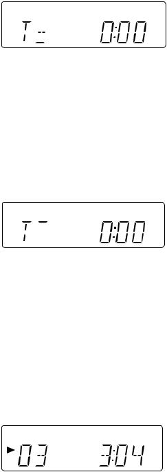
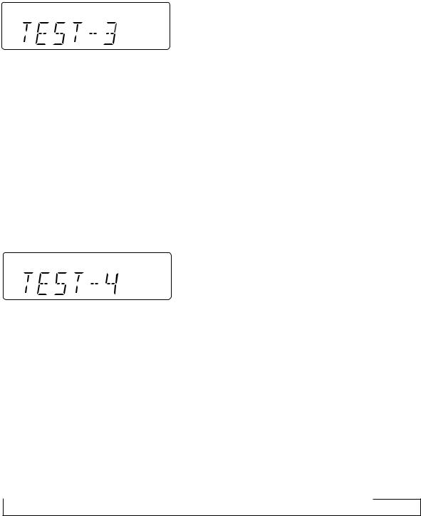
4. Electronic volume Test Mode (TEST 3)
When the test mode is set, the following indication lights for one second.
When this mode is set, BASS/TREBLE is set to 0 (0 dB) and SURROUND mode is set to off, and start-up function is set to CD when volume is -14 dB (STEP 17). The button operations in the test mode are the same as those of ordinary operation excepting sound volume UP/DOWN.
(1)The indication is the same as that of ordinary operation excepting test mode setting.
(2)The sound volume control with the sound volume UP/DOWN button is only the following 3 steps unlike the ordinary state. Volume- ∞ (STEP 0) <-> Volume-14 dB (STEP 23) <-> Volume-0 (STEP 30)
(3)BASS/TREBLE and SURROUND are switched when button operation is performed.
5.Timer test Mode (TEST 4)
When the test mode is set, the following indication lights for one second.
The current time and timer time are set in the following procedure to perform the timer playback.
1.Set the current time to 1:00, set the timer to ON time 1:02, set the function to Tape, and set volume STEP 8. One minute is counted as one second, and the timer playback operation is performed. The fade-in (when playback is started) is executed at a rate of one step for 0.5 sec. After completion of fade-in the fade-out is executed at a rate of one step for 0.5 sec (WAIT 1 sec inserted). After completion of fade-out the power is turned off (after WAIT 1 sec), and the mode is changed to the standby mode.
The indication during operation is the same as that of ordinary timer operation.
6. LCD Test Mode (TEST 5)
When the LCD test mode is set, all the LCD segments are lighted. After that the indication is changed as follows according to the "PLAY" button input.
 Lighting of all segments
  Lighting of odd segments
  Lighting of even segments
– 19 –
XL-560H/E,570H/E
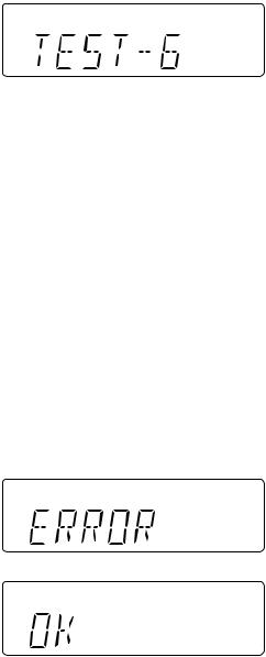
7. Key input diagnosis Test Mode (TEST 6)
When the test mode is set, the following indication appears.
This test mode is intended to check whether all the main unit buttons can be detected. Accordingly, in this test mode checking as to whether the "POWER" button was pressed after all the buttons shown below were pressed is performed. If the result is OK, OK is indicated. Even any one of keys was not pressed, an error is indicated. In case of OK termination or error termination exit from this mode occurs when the "POWER" button is pressed next time, and the standby mode is set.
All the models using this microcomputer do not use the same buttons. Some models do not have specific buttons. Accordingly, the input of the following buttons is detected by using the combination of buttons to be pressed together when this mode is turned on.
The button pressing order is not specified. Checking as to whether all the buttons were pressed is executed.
1. In case of "FF/FWD" + "REC PAUSE" (XL-560E/570E Only)
Since RDS and SURROUND are not provided, the following 11 buttons are detected as all buttons.
PLAY, JOG MODE, BAND, BASS/TREBLE, FUNCTION, MEMORY/SET, REC PAUSE, REW, FF, STOP, CLOCK/TIMER/ SLEEP
2. In case of "FUNCTION" + "RDS PTY-TP" (XL-560H/570H Only)
Since SURROUND and RDS are provided, the following 16 buttons are detected as all buttons.
PLAY, JOG MODE, BAND, BASS/TREBLE, FUNCTION, MEMORY/SET, REC PAUSE, REW, FF, STOP, CLOCK/TIMER/ SLEEP, PTY-TI, EON, APMS, DISPLAY, SURROUND
(RDS circuit is only for XL-560H/570H)
The OK/NG indication of test result is as follows.
– 20 –
 Loading...