


|
- |
|
XG NV4SU |
LCD PROJECTOR |
OPERATION MANUAL |
PROJECTEUR LCD |
MODE D’EMPLOI |
PROYECTOR LCD |
MANUAL DE OPERACION |
ENGLISH
FRANÇAIS
ESPAÑOL
|
|
|
ENGLISH |
|
|
Important |
Information |
|
|
|
|
|
|
|
Before using the LCD projector, please read this operation manual carefully.
OPERATION MANUAL |
ENGLISH |
|
|
IMPORTANT
For your assistance in reporting the loss or theft of your Color LCD Projector, please record the Serial Number located on the bottom of the projector and retain this information. Before recycling the packaging, please be sure that you have checked the contents of the carton thoroughly against the list of “Supplied Accessories” on page 5.
Model No.: XG-NV4SU
Serial No.:
There are two important reasons for prompt warranty registration of your new SHARP LCD Projector, using the REGISTRATION CARD packed with the projector.
1.WARRANTY
This is to assure that you immediately receive the full benefit of the parts, service and labor warranty applicable to your purchase.
2.CONSUMER PRODUCT SAFETY ACT
To ensure that you will promptly receive any safety notification of inspection, modification, or recall that SHARP may be required to give under the 1972 Consumer Product Safety Act,
PLEASE READ CAREFULLY THE IMPORTANT “LIMITED WARRANTY” CLAUSE. |
U.S.A. ONLY |
WARNING: High brightness light source. Do not stare into the beam of light, or view directly. Be especially careful that children do not stare directly into the beam of light.
WARNING: To reduce the risk of fire or electric shock, do not expose this product to rain or moisture.
CAUTION |
RISK OF ELECTRIC SHOCK. |
DO NOT REMOVE SCREWS |
EXCEPT SPECIFIED USER |
SERVICE SCREW. |
CAUTION: TO REDUCE THE RISK OF ELECTRIC SHOCK, |
DO NOT REMOVE COVER. |
NO USER-SERVICEABLE PARTS EXCEPT LAMP UNIT. |
REFER SERVICING TO QUALIFIED SERVICE |
PERSONNEL. |
The lightning flash with arrowhead symbol, within an equilateral triangle, is intended to alert the user to the presence of uninsulated “dangerous voltage” within the product’s enclosure that may be of sufficient magnitude to constitute a risk or electric shock to persons.
The exclamation point within a triangle is intended to alert the user to the presence of important operating and maintenance (servicing) instructions in the literature accompanying the product.
WARNING: FCC Regulations state that any unauthorized changes or modifications to this equipment not expressly approved by the manufacturer could void the user’s authority to operate this equipment.
INFORMATION
This equipment has been tested and found to comply with the limits for a Class A digital device, pursuant to Part 15 of the FCC Rules. These limits are designed to provide reasonable protection against harmful interference when the equipment is operated in a commercial environment. This equipment generates, uses, and can radiate radio frequency energy and, if not installed and used in accordance with the operation manual, may cause harmful interference to radio communications. Operation of this equipment in a residential area is likely to cause harmful interference, in which case the user will be required to correct the interference at his own expense.
The enclosed computer cable and Macintosh adaptor must be used with the device. The cable and adaptor are provided to ensure that the device complies with FCC Class A verification.
E-1
Contents
 Important Information
 Operation
 Useful Features
 Setup & Connections
Maintenance &
Troubleshooting
Appendix
Important Safeguards ……………………………………………………… 3 Usage Guidelines ………………………………………………………… 4 For SHARP Assistance (U.S.A. only) …………………………………… 4 Outstanding Features ……………………………………………………… 5 Supplied Accessories ……………………………………………………… 5 Part Names ………………………………………………………………… 6
Projector ………………………………………………………………… 6 Wireless Mouse Remote Control …………………………………… 7 Operating the Wireless Mouse Remote Control ………………………… 8
Setting Up the Projector (Standard Setup) ……………………………… 10 Adjusting the Height of the Picture ……………………………………… 10 Basic Operations …………………………………………………………… 11 Connecting the Power Cord ………………………………………… 11 Turning on the Main Power …………………………………………… 11 Turning on the Power ………………………………………………… 11 Adjusting the Focus …………………………………………………… 11 Adjusting the Zoom …………………………………………………… 11 Selecting the On-screen Display Language ……………………… 11 Selecting the Video Input System Mode …………………………… 12
Selecting the Input Mode |
…………………………………………… 12 |
|
Checking the Input Mode |
…………………………………………… 13 |
|
Adjusting the Volume |
………………………………………………… 13 |
|
Turning off the Power |
………………………………………………… 13 |
|
Using the Menu Screens |
………………………………………………… 14 |
|
Picture Adjustments ……………………………………………………… 15 Computer Adjustments …………………………………………………… 16 Auto Sync Adjustment ………………………………………………… 16 Manual Adjustment …………………………………………………… 16 Mode Adjustment ……………………………………………………… 16 Initial Reset ……………………………………………………………… 17 Memory Select ………………………………………………………… 17 Computer Mode Memory Adjustments ……………………………… 17 Audio Adjustments ………………………………………………………… 18
Checking the System Setup ……………………………………………… 19 Background Level (VIDEO mode only) ………………………………… 19 Black Screen Function …………………………………………………… 20 Auto Sync Display Function (RGB mode only) ………………………… 20 Blue Screen Function (VIDEO mode only) ……………………………… 21 Using the Input Mode On-screen Display Override Function ………… 21 Using the Reverse/Invert Image Function ……………………………… 22
Relationship between Projector Distance and Picture Size …………… 23 Reversed Image and Ceiling-mount Setups …………………………… 24 Connecting a Computer …………………………………………………… 25 “Plug and Play” Function ……………………………………………… 25 Using the Remote Mouse Receiver and RS-232C Port …………… 25 Connecting to the Computer Input Port …………………………… 26 Connecting Video Equipment …………………………………………… 27
Air Filter Maintenance ……………………………………………………… 28 Lamp/Maintenance Indicators …………………………………………… 29 Replacing the Projection Lamp …………………………………………… 30 Using the Kensington Lock ……………………………………………… 31 Troubleshooting …………………………………………………………… 31
Transporting the Projector ………………………………………………… 32 Connection Pin Assignments ……………………………………………… 33 RS-232C Port Specifications ……………………………………………… 33 Input Signals (Recommended Timing) ………………………………… 35 Specifications ……………………………………………………………… 36 Dimensions ………………………………………………………………… 37
Information |
Important |
|
|
Operation
Features Useful
Connections & Setup
Troubleshooting |
& Maintenance |
|
|
Appendix
E-2

Important |
Information |
|
|
 Important Safeguards
Electrical energy can perform many useful functions. This product has been engineered and manufactured to ensure your personal safety. But IMPROPER USE CAN RESULT IN POTENTIAL ELECTRICAL SHOCK OR FIRE HAZARD. In order not to defeat the safeguards incorporated into this LCD Projector, observe the following basic rules for its installation, use and servicing. For your own protection and reliable usage of your LCD Projector, please be sure to read these “Important Safeguards” carefully before use.
1.Read Instructions—All the safety and operating instructions should be read before the product is operated.
2.Retain Instructions—The safety and operating instructions should be retained for future reference.
3.Heed Warnings—All warnings on the product and in the operating instructions should be adhered to.
4.Follow Instructions—All operating and use instructions should be followed.
5.Cleaning—Unplug this product from the wall outlet before cleaning. Do not use liquid cleaners or aerosol cleaners. Use a damp cloth for cleaning.
6.Attachments—Do not use attachments not recommended by the product manufacturer as they may cause hazards.
7.Water and Moisture—Do not use this product near water – for example, near a bathtub, wash bowl, kitchen sink, or laundry tub; in a wet basement; or near a swimming pool; and the like.
8.Accessories—Do not place this product on an unstable cart, stand, tripod, bracket, or table. The product may fall, causing serious injury to a child or adult, and serious damage to the product. Use only with a cart, stand, tripod, bracket, or table recommended by the manufacturer, or sold with the product. Any mounting of the product should follow the manufacturer’s instructions, and should use a mounting accessory recommended by the manufacturer.
9.A product and cart combination should be moved with care. Quick stops, excessive force,
and uneven surfaces may cause the product and cart combination to overturn. 
10.Ventilation—Slots and openings in the cabinet are provided for ventilation to ensure reliable operation of the product and to protect it from overheating. The openings should never be covered or blocked by placing the product on a bed, sofa, rug, or other similar surface. This product should not be placed in a built-in installation such as a bookcase or rack unless proper ventilation is provided or the manufacturer’s instructions have been adhered to.
11.Power Sources—This product should be operated only from the type of power source indicated on the marking label. If you are not sure of the type of power supply to your home, consult your product dealer or local power company. For products intended to operate from battery power, or other sources, refer to the operating instructions.
12.Grounding or Polarization—This product is equipped with a three-wire grounding-type plug, a plug having a third (grounding) pin. This plug will only fit into a grounding-type power outlet. This is a safety feature. If you are unable to insert the plug into the outlet, contact your electrician to replace your obsolete outlet. Do not defeat the safety purpose of the grounding-type plug.
13.Power-Cord Protection—Power-supply cords should be routed so that they are not likely to be walked on or pinched by items placed upon or against them, paying particular attention to cords at plugs, convenience receptacles, and the point where they exit from the product.
14.Lightning—For added protection for this product during a lightning storm, or when it is left unattended and unused for long periods of time, unplug it from the wall outlet and disconnect the cable system. This will prevent damage to the product due to lightning and power-line surges.
15.Overloading—Do not overload wall outlets, extension cords, or integral convenience receptacles as this can result in a risk of fire or electric shock.
16.Object and Liquid Entry—Never push objects of any kind into this product through openings as they may touch dangerous voltage points or short-out parts that could result in a fire or electric shock. Never spill liquid of any kind on the product.
17.Servicing—Do not attempt to service this product yourself as opening or removing covers may expose you to dangerous voltage or other hazards. Refer all servicing to qualified service personnel.
18.Damage Requiring Service—Unplug this product from the wall outlet and refer servicing to qualified service personnel under the following conditions:
a.If the power-supply cord or plug is damaged.
b.If liquid has been spilled, or objects have fallen into the product.
c.If the product has been exposed to rain or water.
d.If the product does not operate normally by following the operating instructions. Adjust only those controls that are covered by the operating instructions, as an improper adjustment of other controls may result in damage and will often require extensive work by a qualified technician to restore the product to normal operation.
e.If the product has been dropped or damaged in any way.
f.If the product exhibits a distinct change in performance—this indicates a need for service.
19.Replacement Parts—When replacement parts are required, be sure the service technician has used replacement parts specified by the manufacturer or with the same characteristics as the original part. Unauthorized substitutions may result in fire, electric shock, or other hazards.
20.Safety Check—Upon completion of any service or repairs to this product, ask the service technician to perform safety checks to determine that the product is in proper operating condition.
21.Wall or Ceiling Mounting—This product should be mounted to a wall or ceiling only as recommended by the manufacturer.
22.Heat—This product should be situated away from heat sources such as radiators, heat registers, stoves, or other products (including amplifiers) that produce heat.
E-3
 Usage Guidelines
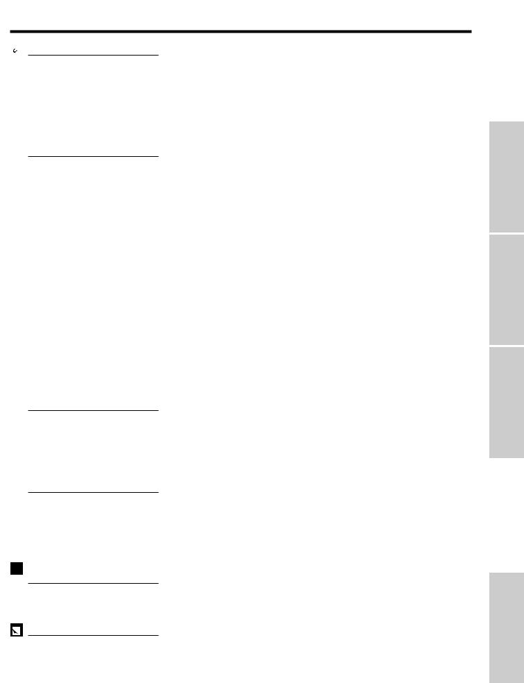
Cautions Concerning the Laser Pointer
The laser pointer on the remote control emits a laser beam from the laser light window. This is a Class II laser which may impair your sight if directed into the eyes. The three marks shown on the right are caution labels for the laser beam.
•Do not look into the laser light window or shine the laser beam on yourself or others. (The laser beam used in this product is harmless when directed onto the skin. However, be careful not to project the beam directly into the eyes.)
•Always use the laser pointer at temperatures between 41°F and 104°F (`5°C and `40°C).
•Use of controls or adjustments, or performance of procedures other than those specified herein may result in hazardous radiation exposure.
CAUTION |
|
"COMPLIES WITH 21 CFR SUBCHAPTER J" |
|||
|
SHARP PLAZA, MAHWAH, NEW JERSEY 07430 |
||||
|
|
SHARP ELECTRONICS CORPORATION |
|||
LASER RADIATION- |
|
TEL : 1-800-BE-SHARP |
|
U.S.A. ONLY |
|
|
|
|
|||
DO NOT STARE INTO BEAM |
|
REMOTE CONTROL |
|
|
|
WAVE LENGTH : 670nm |
|
MODEL NO. : G1462CESA |
|
|
|
|
DC6V (1.5VX4PCS.) |
|
|
|
|
MAX. OUTPUT : 1mW |
|
MADE IN JAPAN |
|
|
|
CLASS II LASER PRODUCT |
|
FABRIQUÉ AU JAPON |
|
|
|
|
|
|
|
|
|
AVOID EXPOSURE-LASER
RADIATION IS EMITTED
FROM THIS APERTURE.
Laser light window
Cautions Concerning the Setup of the Projector
•For minimal servicing and to maintain high image quality, SHARP recommends that this projector be installed in an area free from humidity, dust and cigarette smoke. When the projector is subjected to these environments, the lens and filter must be cleaned more often. Periodically the filter should be replaced and the projector should be cleaned internally. As long as the projector is properly maintained in this manner, use in these environments will not reduce the overall operation life. Please note that all internal cleaning must be performed by an Authorized Sharp Industrial LCD Products Dealer or Service Center.
•Do not expose the projector to extreme heat or cold. Operating temperature: 41°F to 104°F (`5°C to `40°C) Storage temperature: 14°F to 140°F (120°C to `60°C)
•Do not tilt the projector at an angle greater than 5°.
Notes on Operation
•The exhaust vent, the lamp cage cover and adjacent areas may be extremely hot during projector operation. To prevent injury, do not touch these areas until they have sufficiently cooled.
•Allow at least 4 inches (10 cm) of space between the cooling fan (exhaust vent) and the nearest wall or obstruction.
•If the cooling fan becomes obstructed, a protection device will automatically turn off the projector lamp. This does not indicate a malfunction. Remove the projector power cord from the wall outlet and wait at least 10 minutes. Then turn on the power by plugging the power cord back in. This will return the projector to the normal operating condition.
Temperature Monitor Function
If the projector starts to overheat due to setup problems or a dirty air filter, “TEMP.” will flash in the upper- TEMP. left corner of the picture. If the temperature continues to rise, the lamp will turn off, the TEMPERATURE WARNING indicator on the projector will flash, and after a 90-second cooling-off period the power will shut
off. Refer to “Lamp/Maintenance Indicators” on page 29, when “TEMP.” appears on the screen.
•The cooling fan regulates the internal temperature, and its performance is automatically controlled. The sound of the fan may change during projector operation due to changes in the fan speed.
Lamp Monitor Function |
|
|
|
When the projector is turned on after the lamp has been used for 1,900 hours, the LAMP REPLACEMENT |
LAMP |
indicator will light red and “LAMP” will flash in yellow on the screen to advise you to replace the lamp. See |
|
pages 30 and 31 for replacing the lamp. If the lamp has been used for 2,000 hours, the projector power |
|
will automatically turn off and the projector will enter standby mode. Refer to “Lamp/Maintenance Indica- |
|
tors” on page 29, when “LAMP” appears on the screen. |
|
Remote Control Handling Precaution
•Do not expose the remote control to shocks, liquids or high humidity. The remote control may not operate normally if exposed to direct sunlight or other intense light sources. Should this occur, reposition the light source or the projector.
•When not using the remote control, turn off the Main Power switch to avoid draining the batteries.
 For SHARP Assistance (U.S.A. only)
If you encounter any problems during setup or operation of this projector, first take a look at the section “Troubleshooting” on page 31. If this operation manual does not answer your question, please call toll free 1-800-BE-SHARP (1-800-237-4277) for further assistance. Or, send us an e-mail at lcdsupport@sharplcd.com .
Our World Wide Web address is http://www.sharp-usa.com/ .
Information |
Important |
|
|
E-4
Important |
Information |
|
|
 Outstanding Features
The SHARP LCD Projector enables easy projection of large screen, full-color computer and video images that can be projected directly onto a video screen or white wall. This lightweight, convergence-free system allows for easy installation.
DIRECT COMPUTER COMPATIBILITY
A multi-scan RGB input accepts signals from XGA (1,024 dots 2 768 lines compressed), SVGA (800 dots 2 600 lines), VGA (640 dots 2 480 lines) and Macintosh (832 dots 2 624 lines maximum) compatible computers without the need for any additional hardware.
•Due to the native pixel resolution of the LCD panels (804 2 604), this projector will not display Mac 832 2 624 resolution images full screen.
HIGH IMAGE QUALITY
Three LCD panels contain 485,616 2 RGB pixels to achieve exceptionally bright, high quality images.
INTELLIGENT COMPRESSION
XGA images are compressed and projected without image data loss.
VERSATILE WIRELESS MOUSE REMOTE CONTROL
•Built-in wireless mouse allows simultaneous operation of projector and computer.
•Built-in laser pointer enables professional presentations.
FLEXIBLE USE
•In addition to standard front projection, the menu driven functions can be used to instantly reverse the image for rear projection and invert the image for ceiling mounting projection.
•Screen projection size adjustable from 40 to 300 inches.
USE WITH “PLUG AND PLAY”
Plug and Play function compatible with VESA DDC 1 and DDC 2B standards.
MULTILINGUAL ON-SCREEN DISPLAY
On-screen Display can be set to any of eight languages.
AUTO SYNC FUNCTION
Automatically synchronizes RGB input signals from a computer for optimum images.
BUILT-IN SPEAKER
Built-in 2 W amplifier and speaker eliminate the need for external audio components.
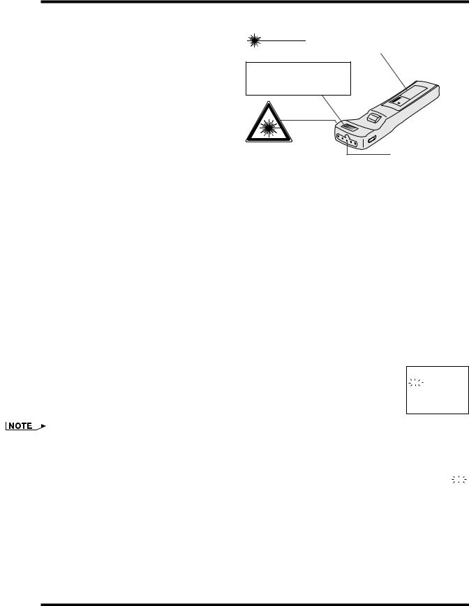
Supplied Accessories
Remote control |
Four AA size |
Computer cable |
Macintosh adaptor |
Remote mouse receiver |
RRMCG1462CESA |
batteries |
QCNW-5108CEZZ |
QPLGJ1512CEZZ |
RUNTK0632CEZZ |
|
Mouse control cable for |
Mouse control cable for |
|
|
Mouse control serial cable |
IBM PS/2 |
Mac |
Computer audio cable |
Extra air filter |
QCNW-5112CEZZ |
QCNW-5113CEZZ |
QCNW-5114CEZZ |
QCNW-4870CEZZ |
PFILD0076CEZZ |
Lens cap |
Power cord |
Carrying bag |
|
|
GCOVH1307CESA |
QACCU5013CEZZ |
GCASN0001CESA |
|
|
E-5
 Part Names
For details on the use of each control and terminal, refer to the page number indicated in the brackets.
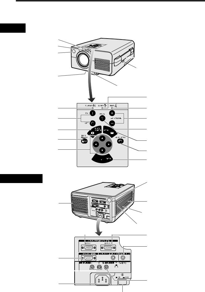
Projector
Front View
Zoom knob [p. 11]
Focus knob [p. 11]
Remote control sensor [p. 8]
Air filter [p. 28]/Cooling fan |
(Intake vent) |
 Carrying handle [p. 32]
 Kensington Security Standard connector [p. 31]
Adjuster release [p. 10]
Information |
Important |
|
|
POWER indicator [pp. 11, 13]
POWER buttons (ON/OFF) [pp. 11, 13, 30, 31]
BLACK SCREEN button [p. 20]
INPUT SELECT button [pp. 12, 13, 16]
ADJUSTMENT buttons (¶/Ä/§ / ©)
[pp. 11, 12, 14–22, 31]
Side and Rear View
Cooling fan (Exhaust vent)
COMPUTER INPUT 1 port (HD-15)  [pp. 8, 25, 26, 33]
RS-232C port (9-pin D-sub) [pp. 8, 25, 33, 34]
AUDIO INPUT terminals: RCA  [p. 27]
AC socket
LAMP REPLACEMENT indicator [pp. 11, 13, 29]
TEMPERATURE WARNING indicator [pp. 4, 29]
VOLUME buttons (`/1) [p. 13]
MUTE button [p. 13]
MENU button [pp. 11, 12, 14–22]
AUTO SYNC button [p. 16]
ENTER button
[pp. 11, 12, 14–22, 31]
Remote control sensor [p. 8]
Speaker
Cooling fan (Intake vent)
Air filter [p. 28]
COMPUTER INPUT 2 port (HD-15) [pp. 8, 25, 26, 33]
AUDIO OUTPUT terminal (3.5 mm stereo minijack) [p. 27]
 COMPUTER AUDIO INPUT terminal
(3.5 mm stereo minijack) [p. 25]
 S-VIDEO INPUT terminal: 4-pin mini DIN [p. 27]
VIDEO INPUT terminal: RCA [p. 27]
MAIN POWER switch  [pp. 8, 11, 13, 28, 30, 31]
E-6
Important |
Information |
|
|
Part Names
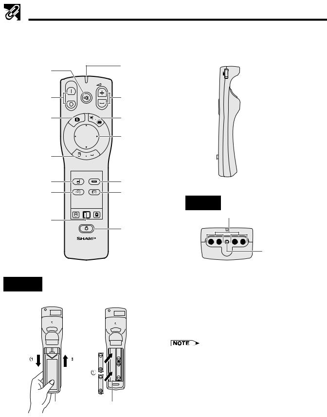
Wireless Mouse Remote Control
Front View |
|
Side View |
|
|
|
MUTE button [p. 13]
POWER buttons (ON/OFF)
[pp. 11, 13, 30, 31]
BLACK SCREEN button [p. 20]
RIGHT-CLICK/ ENTER button [pp. 9, 11, 12, 14–22]
INPUT SELECT button (COMPUTER) [pp. 12, 16]
ON |
VOL |
|
MUTE |
OFF |
|
BLACK |
LASER |
|
|
SCREEN |
MENU |
R-CLICK ENTER
COMPUTER VIDEO
CHECK AUTO SYNC
TRANSMIT indicator
VOLUME buttons (`/1) [p. 13]
LASER POINTER/ MENU button [pp. 9, 11, 12, 14–22]
MOUSE/ ADJUSTMENT buttons (¶/Ä/§/©) [pp. 9, 11, 12, 14–22]
INPUT SELECT button (VIDEO) [pp. 12, 16]
ON R/C OFF

 MAIN POWER switch [pp. 8, 9]
 LEFT-CLICK button [p. 9]
INPUT CHECK |
AUTO SYNC |
(CHECK) button |
button [p. 16] |
[pp. 13, 21] |
|
MOUSE |
ADJ. |
MOUSE/ADJUST- |
LIGHT |
MENT switch |
BACKLIGHT |
|
[pp. 8, 9, 11, |
||
button [p. 9] |
||
14, 31] |
||
LCD PROJECTOR |
||
|
Rear View
Battery |
Battery |
cover |
compartment |
Top View
 Remote control signal transmitter
Laser light window [pp. 4, 9]
Inserting the batteries
1.Press in and downward on the arrow mark and remove the battery cover.
2.Insert four AA size batteries making sure their polarities match the ` and 1 marks inside the battery compartment.
3.Insert the side tabs of the battery cover into their slots and press in the cover until properly seated.
Incorrect use of batteries may cause them to leak or burst.
•Insert the batteries with the ` and 1 polarities as indicated.
•Do not mix different brands of batteries. The life expectancy of the new batteries will be shortened and the old batteries may leak.
•Maintain the batteries in clean condition.
•Remove the batteries if the remote control will not be used for an extended period of time.
•When the batteries have been used up, remove them immediately to prevent leakage and damage. Leaked battery fluid may irritate the skin. Remove any battery fluid by wiping with a cloth.
•Due to storage conditions and the shelf life of the supplied batteries, they may run out after a short time. Should this occur, replace them with new batteries as soon as possible.
E-7
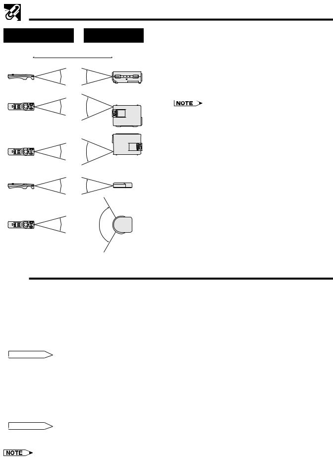
Part Names
Transmission range |
Reception range |
Remote control and remote mouse receiver |
|
positioning |
|||
|
|
||
Max. distance: 238 (7 m) |
The remote control can be used to control the projec- |
||
tor in the ranges shown on the left. |
|||
|
Projector |
The remote mouse receiver can be used with the |
|
30˚ |
30˚ |
remote control in the ranges shown to control the |
|
|
|
mouse functions of a connected computer. (See |
|
|
|
page 25 for details.) |
|
30˚ |
45˚ |
• The signal from the remote control can be reflected off |
|
|
|
||
the screen for easy operation. However, the effective distance of the signal may differ due to the screen material.
30˚ 45˚
Remote mouse receiver
30˚ 30˚
30˚ 120˚
 Operating the Wireless Mouse Remote Control
Information |
Important |
|
|
This remote control can be used for basic operations of the projector as well as operations of a connected computer by using the wireless mouse functions and remote mouse receiver. Together with the laser pointer, this can help you create a more professional presentation.
a. Connecting the projector to the computer
Connect the projector and the computer with the supplied computer cable. When using the remote mouse receiver to operate the computer, connect the remote mouse receiver to the computer. See pages 25 and 26 for details on these connections.
 CAUTION
•Always turn on the projector first, then the computer on.
b.Wireless Mouse Operation
1.After connecting the projector and the computer, turn them on.
2.Slide the MAIN POWER switch on the side of the remote control to ON.
3.When using the remote control as a wireless mouse, slide the MOUSE/ADJUSTMENT switch to the MOUSE position. When using the remote control to operate the projector, slide the switch to the ADJ. position.
 CAUTION
•Do not connect or remove the mouse control cable and the computer cable to or from the computer while it is on. This may damage the computer.
•The wireless mouse or RS-232C function may not operate if your computer port is not correctly set up. Please refer to the operation manual of the computer for details on setting up/installing the correct mouse driver.
E-8
Important |
Information |
|
|
Operating the Wireless Mouse Remote Control
|
|
|
|
|
|
|
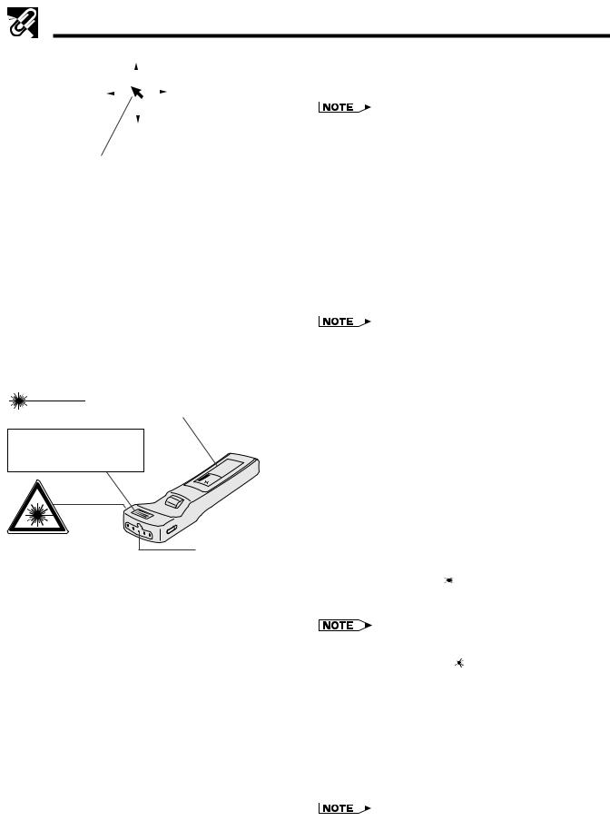
c. Moving the mouse cursor |
|
|
|
|
|
|
|
|
Press ¶/Ä/§/© on the remote control to move |
|
|
|
|
|
|
|
|
||
|
|
|
|
|
|
|
the mouse cursor on the screen. |
|
|
|
|
|
|
|
|
• The amount of pressure applied to the ¶/Ä/§/© buttons |
|
|
|
|
|
|
|
|
||
|
|
|
|
|
|
|
||
|
|
|
|
|
|
|
||
|
|
|
|
|
|
|
determines the speed the mouse cursor travels. If you |
|
|
|
|
|
|
|
|
lightly press the periphery of the ¶/Ä/§/© buttons, the |
|
Mouse cursor |
mouse cursor moves slowly. If you press hard, the mouse |
|||||||
cursor moves quickly. |
||||||||
|
|
|
|
|
|
|
||
•The mouse sensitivity can also be adjusted from your computer’s operating system.
d.Selecting the mouse button for two-
button mouse systems
Use LEFT-CLICK on the back of the remote control to correspond to the left mouse button on two-button mouse systems, and RIGHTCLICK on the front of the remote control to correspond to the right button.
CAUTION |
|
"COMPLIES WITH 21 CFR SUBCHAPTER J" |
|||
|
SHARP PLAZA, MAHWAH, NEW JERSEY 07430 |
||||
|
|
SHARP ELECTRONICS CORPORATION |
|||
LASER RADIATION- |
|
TEL : 1-800-BE-SHARP |
|
U.S.A. ONLY |
|
|
|
|
|||
DO NOT STARE INTO BEAM |
|
REMOTE CONTROL |
|
|
|
WAVE LENGTH : 670nm |
|
MODEL NO. : G1462CESA |
|
|
|
|
DC6V (1.5VX4PCS.) |
|
|
|
|
MAX. OUTPUT : 1mW |
|
MADE IN JAPAN |
|
|
|
CLASS II LASER PRODUCT |
|
FABRIQUÉ AU JAPON |
|
|
|
|
|
|
|
|
|
AVOID EXPOSURE-LASER
RADIATION IS EMITTED
FROM THIS APERTURE.
Laser light window
Button name |
Position of MOUSE/ADJUSTMENT switch |
||
|
MOUSE |
ADJ. |
|
|
|
|
|
LASER POINTER/MENU |
LASER POINTER (GREEN) |
MENU (RED) |
|
|
|
|
|
RIGHT-CLICK/ENTER |
RIGHT-CLICK (GREEN) |
ENTER (RED) |
|
|
|
|
|
MOUSE/ADJUSTMENT |
MOUSE (NOT LIT) |
ADJUSTMENT (NOT LIT) |
|
|
|
|
|
LEFT-CLICK |
ON (NOT LIT) |
— |
|
|
|
|
|
BLACK SCREEN |
|
|
|
|
|
|
|
POWER ON/OFF |
|
|
|
|
|
|
|
VOLUME |
|
|
|
|
|
|
|
MUTE |
ON (RED) |
||
|
|||
COMPUTER |
|||
|
|
||
|
|
|
|
VIDEO |
|
|
|
|
|
|
|
INPUT CHECK |
|
|
|
|
|
|
|
AUTO |
|
|
|
SYNCHRONIZATION |
|
|
|
|
|
|
|
E-9
•For one-button systems, use either the LEFT-CLICK or
RIGHT-CLICK button.
Using the laser pointer
The laser pointer on the remote control emits a laser beam from the laser light window. This is a Class II laser which may impair your sight if directed into the eyes. The three marks shown on the left are caution labels for the laser beam.
•Do not look into the laser light window or shine the laser beam on yourself or others. (The laser beam used in this product is harmless when directed onto the skin. However, be careful not to project the beam directly into the eyes.)
•Always use the laser pointer at temperatures between 41°F and 104°F (`5°C and `40°C).
•Use of controls or adjustments, or performance of procedures other than those specified herein may result in hazardous radiation exposure.
Press LASER POINTER ( ) to activate the laser pointer. When the button is pressed, the light stays on. When the button is released, the light automatically goes off.
•For safety reasons, the laser pointer automatically goes off after 1 minute of continuous use. To turn it on again,
press LASER POINTER ( ) one more time.
Using the remote control in a dark room
When the position of the MOUSE/ADJUSTMENT switch is changed, the functions of certain buttons on the remote control also change. You can determine the function of a button by the color of its backlight display. See the table on the left.
Press BACKLIGHT to turn on the backlights of the operation buttons for about five seconds.
•If the MAIN POWER switch on the remote control is left on for more than 10 minutes without operation, the power will automatically turn off. To turn the power back on, press any button on the remote control for more than one second.
 Setting Up the Projector (Standard Setup)
Optimal image quality can be achieved when the projector is positioned perpendicular to the screen with all feet flat and level.
•Position the screen so that it is not in direct sunlight or room light. Light falling directly onto the screen washes out colors, making viewing difficult. Close the curtains and dim the lights when setting the screen in a sunny or bright room.
Example of a standard setup
Top View |
|
Side View |
|
|
|
90˚ |
90˚ |
Lens center |
Operation |
|
Lens center |
|
The projector lens should be centered in the middle of the screen.
If the lens center is not perpendicular to the screen, the image will be distorted, making viewing difficult.
•For information on projector distance and picture size, see page 23.
•For reversed image and ceiling-mount setups, see page 24.
•A polarizing screen cannot be used with this projector.
 Adjusting the Height of the Picture
You can adjust the height of the picture by raising the projector with the adjuster release.
a |
a. Extending the adjuster leg |
Press the adjuster release and lift the projector to the desired angle.
Adjuster release
b |
b. Locking the adjuster leg in position |
Remove your hand from the adjuster release, and then release the projector once you are sure the adjuster leg has locked in position.
Returning the projector to its original position
While holding the projector, press the adjuster release and slowly lower the projector to its original position.
• The projector is adjustable up to approximately 5° from
Adjuster release the horizontal.
• When an adjustment is made, the image may become distorted, depending on the relative positions of the projector and the screen.
 CAUTION
• Do not press the adjuster release when the adjuster leg is extended without firmly holding the projector.
• Do not hold the lens when lifting or lowering the projector.
• When lowering the projector, be careful not to get your fingers caught in the area between the adjuster leg and the projector.
E-10
Operation
 Basic Operations
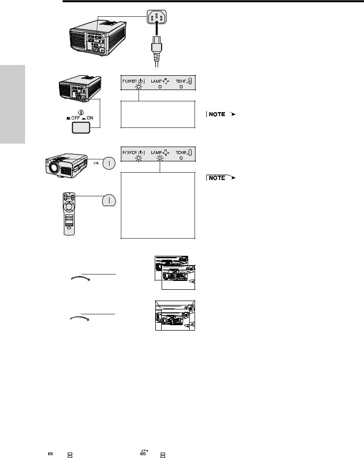
a
b
When the main power is on, the POWER indicator lights up red.
a. Connecting the Power Cord
Plug the supplied power cord into the AC socket on the back of the projector.
b. Turning on the Main Power
Press the MAIN POWER switch on the back of the projector. The POWER indicator lights up red and the projector enters standby mode.
•When the main power is not on, the remote control cannot be used to operate the projector.
c |
|
c. Turning on the Power |
|
|
Press POWER ON on the projector or the |
|
|
remote control. |
or |
When the power is on, |
|
the LAMP REPLACE- |
• The flashing green LAMP REPLACEMENT indicator |
|
ON |
MENT indicator flashes |
shows that the lamp is warming up. Wait until the indica- |
|
to show the operating |
tor stops flashing before operating the projector. |
|
condition of the lamp. |
• If the power is turned off and then immediately turned on |
|
Green: Lamp is ready. |
again, it may take a short while before the lamp turns on. |
|
Flashing green: Warming |
(During this period, the LAMP REPLACEMENT indicator |
|
up. |
flashes.) |
|
Red: Change the lamp. |
• After the projector is unpacked and turned on for the first |
|
|
time, a slight odor may be emitted from the exhaust vent. |
|
|
This odor will soon disappear with use. |
d
Focus knob
e
Zoom knob
d. Adjusting the Focus
Slide the focus knob until the image on the screen becomes clear.
e. Adjusting the Zoom
Slide the zoom knob. The image can be adjusted to the desired size within the zoom range.
|
|
|
On-screen Display |
|||||
f.1 |
|
|
f.2 |
|||||
|
|
|
|
|
|
|
|
|
|
|
|
|
|
|
|
|
|
|
|
|
|
|
|
L A N G U A G E |
|
|
|
|
|
|
|
|
|
|
|
|
R G B 1 A D J . |
|
|
|
|
E N G L I S H |
|
|
|
|
|
|
|
|
|
|
|
|
R G B 1 I N P U T A D J . |
|
|
g |
|
D E U T S C H |
|
|
|
|
|
|
|
|
|
|
|
|
I M A G E A D J . |
|
|
|
E S P A Ñ O L |
|
|
|
|
|
|
|
|
|
|
|
|
|
A U D I O |
|
|
|
N E D E R L A N D S |
|
||
|
|
|
|
|
|
|
||
|
S Y S T E M S E T U P |
|
|
F R A N Ç A I S |
||||
|
|
|
|
|
|
|
|
|
|
L A N G U A G E |
|
|
|
|
I T A L I A N O |
|
|
|
|
|
|
|
|
|
||
|
|
|
|
|
|
S V E N S K A |
|
|
|
|
|
|
|
|
|||
|
|
|
|
|
|
|
|
|
|
: S E L . ENTER : N E X T |
|
|
|
: S E L . ENTER : E N T E R |
|||
|
MENU : E N D |
|
|
|
MENU : E N D |
|||
|
|
|
|
|
|
|
|
|
E-11
f.Selecting the On-screen Display Language
(See page 14 for details on using the
menu screens.)
The On-screen Display is set to “ENGLISH” at the factory. The language for the On-screen Display can be set to English, German, Spanish, Dutch, French, Italian, Swedish or Japanese.
1.Press MENU to display the menu screen. Press ADJUSTMENT ¶/Ä to select “LANGUAGE”. Then press ENTER to display the “LANGUAGE” screen.
2.Press ADJUSTMENT ¶/Ä to select the language you want to display on the screen. Then press ENTER. The On-screen Display is now programed to display in the language selected.
 Loading...