


|
|
|
|
|
|
|
|
|
|
|
|
|
|
|
|
|
|
|
|
|
|
|
|
|
|
|
MICRO COMPONENT SYSTEM |
MODEL |
|
||
|
|
|
XL-30H |
|
|||
|
|
|
OPERATION MANUAL |
|
|||
|
|
|
|
|
|
|
|
|
|
|
|
|
|
|
|
Thank you for purchasing this SHARP product. To obtain the best performance from this product please read this manual carefully.
It will guide you in operating your SHARP product.
XL-30H Micro Component System consisting of XL30H (main unit) and CP-XL40H (speaker system).
CONTENTS |
|
|
Page |
SPESIAL NOTES ........................................... |
1-2 |
ACCESSORIES ................................................. |
3 |
PRECAUTIONS .............................................. |
3-4 |
NAMES OF CONTROLS AND INDICATORS |
.. 5-6 |
PREPARATION FOR USE ............................. |
7-8 |
SETTING THE CLOCK ..................................... |
9 |
SOUND CONTROL ......................................... |
10 |
COMPACT DISC OPERATION .................. |
11-13 |
|
Page |
CASSETTE OPERATION ................................ |
14 |
RADIO OPERATION .................................. |
15-16 |
RECORDING ................................................... |
17 |
HOW TO USE THE BUILT-IN TIMER ......... |
18-19 |
HEADPHONES ................................................ |
20 |
RESETTING THE MICROCOMPUTER ........... |
20 |
MAINTENANCE .............................................. |
20 |
SPECIFICATIONS ........................................... |
21 |
**XL-30H(SUK).FRONT |
1 |
00.2.4, 4:44 PM |
SPECIAL NOTES
NOTE FOR USERS IN THE U.K.
The mains lead of this product is fitted with a nonrewireable (moulded) plug incorporating a 3A fuse. Should the fuse need to be replaced, a BSI or ASTA approved BS 1362 fuse marked  or
or  and of the same rating as above, which is also indicated on the pin face of the plug must be used.
Always refit the fuse cover after replacing the fuse. Never use the plug without the fuse cover fitted.
In the unlikely event of the socket outlet in your home not being compatible with the plug supplied, cut-off the mains plug and fit an appropriate type.
DANGER:
The fuse from the cut-off plug should be removed and the cut-off plug destroyed immediately and disposed of in a safe manner.
Under no circumstances should the cut-off plug be inserted elsewhere into a 13A socket outlet as a serious electric shock may occur.
To fit an appropriate plug to the mains lead, follow the instructions below:
IMPORTANT:
The wires in the mains lead are coloured in accordance with the following code:
Blue : Neutral Brown : Live
As the colours of the wires in the mains lead of this product may not correspond with the coloured markings identifying the terminals in your plug, proceed as follows:
●The wire which is coloured blue must be connected to the plug terminal which is marked N or coloured black.
●The wire which is coloured brown must be connected to the plug terminal which is marked L or coloured red.
Ensure that neither the brown nor the blue wire is connected to the earth terminal in your three pin plug.
Before replacing the plug cover, make sure that:
●If the new fitted plug contains a fuse, its value is the same as that removed from the cut-off plug.
●The cord grip is clamped over the sheath of the mains lead and not simply over the lead wires.
IF YOU HAVE ANY DOUBT, CONSULT A QUALIFIED ELECTRICIAN.
SERVICE INFORMATION
In the unlikely event of your equipment requiring repair, please contact the dealer or supplier from whom it was purchased. Where this is not possible, please contact the telephone number listed below.
You will then be given details of how to obtain service.
- 0345-125387 -
Please note; all calls will be charged at local rate.
Certain replacement parts and accessories may be obtained from our main parts distributor.
WILLOW VALE ELECTRONICS LTD. MANCHESTER 0161-682-1415 READING 01189-876444
In the unlikely event of this equipment requiring repair during the guarantee period, you will need to provide proof of the date of purchase to the repairing company.
Please keep your invoice or receipt, which is supplied at the time of purchase.
1
**XL-30H(SUK)P01-P08 |
1 |
00.2.2, 3:53 PM |
(Continued)
●Recording and playback of any material may require consent, which SHARP is unable to give. Please refer particularly to the provisions of the Copyright Act 1956, the Dramatic and Musical Performers Protection Act 1958, the Performers Protection Acts 1963 and 1972 and to any subsequent statutory enactments and orders.
●This equipment complies with the requirements of Directives 89/336/EEC and 73/23/EEC as amended by 93/68/EEC.
●When the ON/STAND-BY button is set at STAND-BY position, mains voltage is still present inside the unit.
When the ON/STAND-BY button is set at STAND-BY position, the unit may be brought into operation by the timer mode or remote control.
Warning:
●This unit contains no user serviceable parts.
Never remove covers unless qualified to do so. This unit contains dangerous voltages, always remove mains plug from the socket before any service operation and when not in use for a long period.
Warning:
●To prevent fire or shock hazard, do not expose this appliance to dripping or splashing. No objects filled with liquids, such as vases, shall be placed on the apparatus.
CAUTION
Use of controls, adjustments or performance of procedures other than those specified herein may result in hazardous radiation exposure.
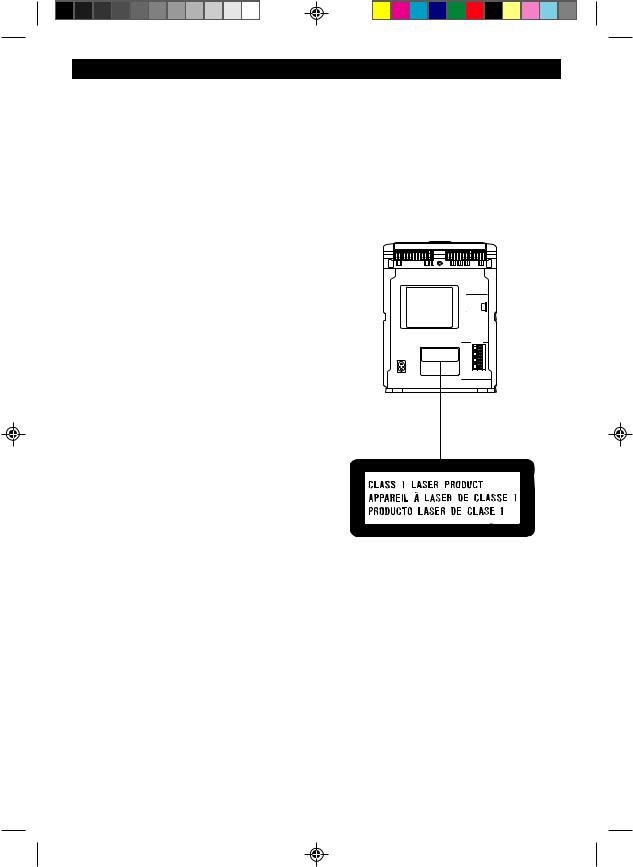
As the laser beam used in this compact disc player is harmful to the eyes, do not attempt to disassemble the cabinet. Refer servicing to qualified personnel only.
2
**XL-30H(SUK)P01-P08 |
2 |
00.2.2, 3:53 PM |
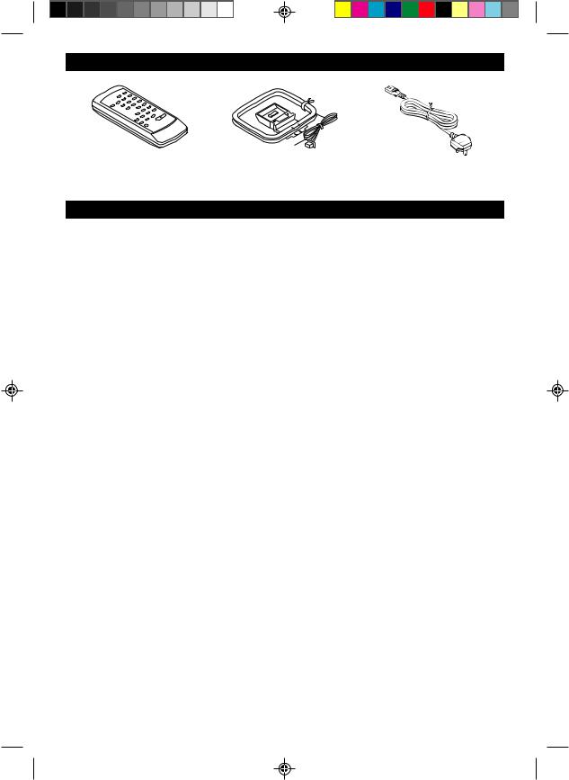
ACCESSORIES
Remote control × 1 |
FM/AM loop aerial × 1 |
AC power lead × 1 |
|
|
|
Note:
Parts and equipment mentioned in this operation manual other than those in the drawing are not included.
PRECAUTIONS
■ General
●Please ensure that the equipment is positioned in a well ventilated area and ensure that there is at least 10cm (4”) of free space along the sides and back. There must also be a minimum of 20cm (8”) of free space on the top of the unit.
●Do not use oil, solvents, petrol, paint thinners or insecticides on the unit.
●Do not expose the unit to moisture, to temperatures higher than 60°C (140°F) or to extreme low temperatures.
●Keep the unit away from direct sunlight, strong magnetic fields, excessive dust, humidity and electronic/electrical equipment (home computers, facsimiles, etc.) which generate electrical noise.
●Hold the AC power plug by the head when removing it from the AC socket, as pulling the lead can damage internal wires.
●When cleaning the heads, pinch roller, etc., remove the AC power plug from the wall socket as the unit contains high voltages.
Do not remove the outer cover, as this may result in electric shock. Refer internal service to your local SHARP service facility.
●Use the unit on a firm, level surface free from vibration, and do not place anything on the top of the unit.
●If an electrical storm is taking place near you, it is suggested that you disconnect the AC power lead from the AC socket for safety.
●The ventilation should not be impeded by covering the ventilation openings with items, such as newspapers, tablecloths, curtains, etc.
●No naked flame sources, such as lighted candles, should be placed on the apparatus.
●Attention should be drawn to the environmental aspects of battery disposal.
●The apparatus is designed for use in moderate climate.
Warning:
The voltage used must be the same as that specified on this unit. Using this product with a higher voltage than that which is specified is dangerous and may result in a fire or other type of accident causing damage.
SHARP will not be held responsible for any damage resulting from use of this unit with a voltage other than that which is specified.
3
**XL-30H(SUK)P01-P08 |
3 |
00.2.2, 3:53 PM |
(Continued)
■ Volume control
The sound level at a given volume setting depends on a combination of speaker efficiency, location and various other factors.
It is advisable to avoid exposure to high volume levels, which occur whilst turning the unit on with the volume control setting up high, or whilst continually listening at high volumes.
■ Condensation
Sudden temperature changes, storage or operation in an extremely humid environment may cause condensation inside the cabinet (CD pickup, tape heads, etc.) or on the transmitter LED on the remote control.
Condensation can cause the unit to malfunction. If this happens, leave the power on with no disc (or cassette) in the unit until normal playback is possible (about 1 hour). Wipe off any condensation on the transmitter LED with a soft cloth before operating the unit.
Warning:
CD players use a laser pickup which can damage the eyes if viewed directly. Do not look at the pickup, and do not touch the pickup directly.
■ Care of compact discs
Compact discs are fairly resistant to damage, however mistracking can occur due to the accumulation of dirt on the disc surface.
Follow the guidelines below for maximum enjoyment from your CD collection and player.
●Do not write on either side of the disc, particularly the non-label side. Signals are read from the non-label side. Do not mark this surface.
●Keep your discs away from direct sunlight, heat, and excessive moisture.
●Always hold the CDs by the edges. Fingerprints, dirt, or water on the CDs can cause noise or mistracking. If a CD is dirty or does not play properly, clean it with a soft, dry cloth, wiping straight out from the centre, along the radius.
■ Cassette tape
●For playback, use normal or low-noise tape for the best sound. (Metal or CrO2 tape is not recommended.)
For recording, use only normal tape.
●Do not use C-120 tapes, tapes with large diameter reels, or poor-quality tapes, as they may cause malfunctions.
●Before loading a tape into the cassette compartment, tighten the slack with a pen or pencil.
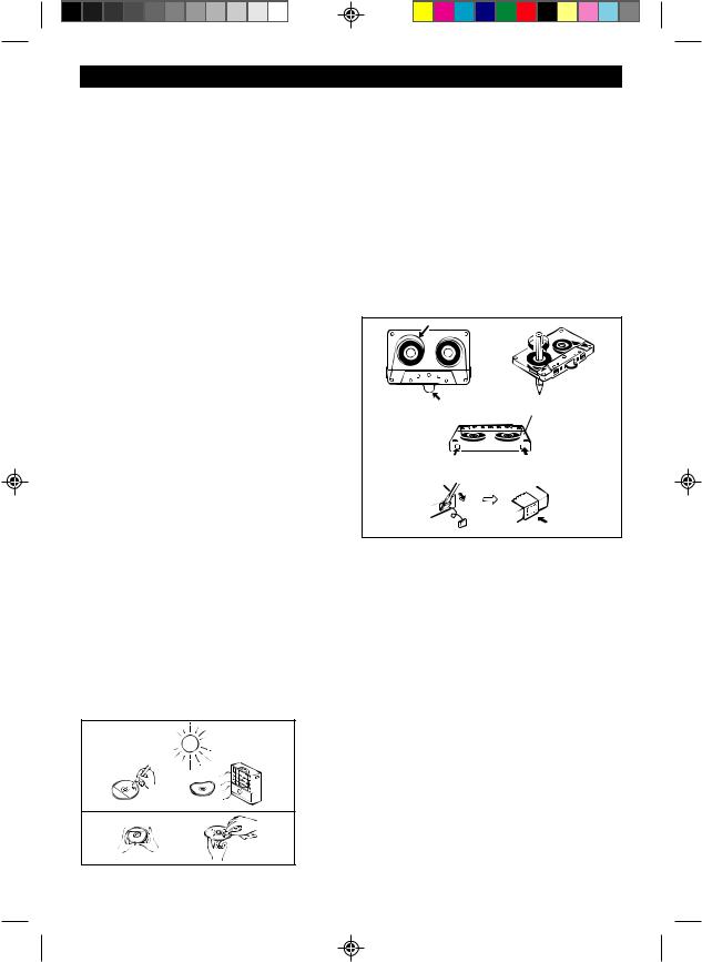
●Cassettes have removable tabs which prevent accidental recording or erasing from taking place. Removing the tab will protect the corresponding side from being erased. Cover the tab holes with adhesive tape to erase or record again.
Side A (1)
Tab for side B (2) Tab for side A (1)
NO
YES
Correct
4
**XL-30H(SUK)P01-P08 |
4 |
00.2.2, 3:53 PM |
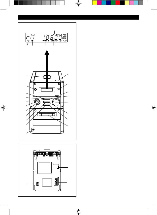
NAMES OF CONTROLS AND INDICATORS
1 2 3
4 |
5 |
6 |
7 |
8 |
9 |
10 |
21 |
|
|
||
11 |
22 |
|
|
||
12 |
23 |
|
24 |
||
13 |
||
|
||
14 |
25 |
|
15 |
|
|
16 |
26 |
|
17 |
||
|
||
18 |
27 |
|
19 |
28 |
|
20 |
|
■Front panel
1.Timer Indicator
2.Record Indicator
3.Sleep Indicator
4.(CD) Repeat Indicator
5.(CD) Play Indicator
6.(CD) Random Indicator
7.(CD/TUNER) Memory Indicator
8.FM Stereo Mode Indicator
9.FM Stereo Indicator
10.CD Compartment
11.On/Stand-by Button
12.(CD/TAPE) Stop Button (TUNER) Memory Clear Button
13.Record Pause Button
14.Bass/Treble Selector Button
15.Memory/Set Button
16.Clock/Timer/Sleep Button
17.Band Selector Button
18.(CD) Review Button (TAPE) Rewind Button
(TUNER) Tuning Down Button
19.Function Selector Button
20.Headphone Socket
21.CD Eject Button
22.Remote Control Sensor
23.Volume Select Button
24.(CD) Play/Pause Button (TAPE) Play Button
25.Jog Dial
26.(CD) Cue Button
(TAPE) Fast Forward Button (TUNER) Tuning Up Button
27.Volume/Jog Dial Selector Button
28.Cassette Compartment
■Rear panel
1.AC Power Input Socket
2.FM/AM Loop Aerial Socket
3.Speaker Terminals
|
2 |
1 |
3 |
|
5
**XL-30H(SUK)P01-P08 |
5 |
00.2.2, 3:53 PM |

(Continued)
|
■ Speaker section |
|
|
1. |
Bass Reflex Duct |
1 |
2. |
Full-Range Speaker |
3. |
Speaker Wire |
|
2
3
|
1 |
|
|
2 |
|
3 |
6 |
|
4 |
7 |
|
5 |
8 |
|
9 |
||
|
||
|
12 |
|
10 |
13 |
|
11 |
14 |
|
15 |
19 |
|
20 |
||
16 |
21 |
|
17 |
|
|
18 |
22 |
■Remote control
1.Remote Control Transmitter LED
●Tuner control section
2.Preset Up/Down Buttons
●CD control section
3.Clear Button
4.Random/Repeat Button
5.Memory Button
6.Stop Button
7.Play/Pause Button
8.Track Down/Review Button
9.Track Up/Cue Button
●Tape control section
10.Record Pause Button
11.Rewind Button
12.Stop Button
13.Play Button
14.Fast Forward Button
●Common section
15.Sleep Button
16.Bass Up/Down Buttons
17.Function Selector Buttons
18.On/Stand-by Button
19.Timer Button
20.Clock Button
21.Treble Up/Down Buttons
22.Volume Up/Down Buttons
6
**XL-30H(SUK)P01-P08 |
6 |
00.2.2, 3:53 PM |
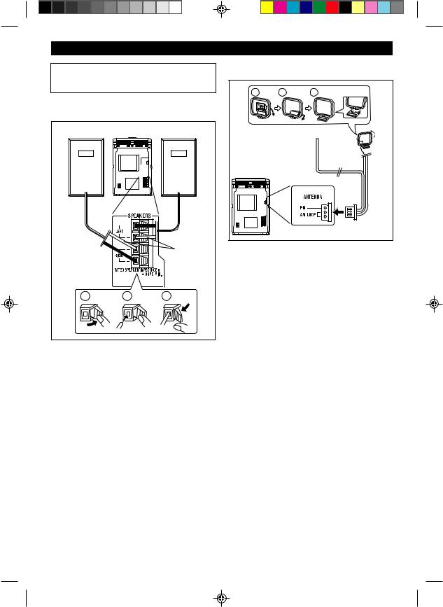
PREPARATION FOR USE
●Unplug the AC power lead from the AC socket before connecting or disconnecting any com-
ponent. |
|
|
■ Speaker connection |
|
|
Right speaker |
|
Left speaker |
|
|
White |
|
|
line |
1 |
2 |
3 |
Connect each speaker wire to the SPEAKER terminals as shown.
Use speakers with an impedance of 4 ohms or more.
Use of speakers with an impedance less than 4 ohms may damage your unit.
Notes:
●Connect the wire with the white line to the minus (-) terminal and the plain wire to the plus (+) terminal.
●Do not mix the right channel and left channel wiring when connecting the speakers to the unit.
●Do not let the bare speaker wires touch each other as this may damage the amplifier and/or speakers.
●The speaker grille is not removable.
■ Aerial connection |
|
||
1 |
2 |
3 |
|
|
FM aerial |
AM |
|
|
|
|
loop |
|
|
|
aerial |
Connect the aerial wire to the ANTENNA socket.
FM aerial
Position the FM aerial wire in the direction where the strongest signal can be received.
AM loop aerial
Position the AM loop aerial for optimum reception. Place the AM loop aerial on a shelf, etc., or attach it to a stand or wall with screws (not supplied).
Notes:
●Do not place the aerial on the main unit as it may result in noise pickup from the internal digital electronics.
Place the aerial away from the unit for better reception.
●If the AM loop aerial and the FM aerial wire are placed near the AC power lead, interference may result.
●Do not connect the attached FM aerial to an external FM aerial. Otherwise, trouble may occur.
7
**XL-30H(SUK)P01-P08 |
7 |
00.2.2, 3:53 PM |
 Loading...