


Order Number: MCUK960901C8
Service Manual
G500 Personal Cellular Telephone Handheld portable
EB-G500
Car mount kit
EB-HF500Z
Dual charger
EB-CR500
DC Adaptor
EB-CD400
Issue 1
Revision 0
This Service Manual is copyright and issued on the strict understanding that it is not to be reproduced, copied, or disclosed to any third party, either in whole or part, without the prior written consent of Matsushita Communication Industrial UK Ltd.
Every care has been taken to ensure that the contents of this manual give an accurate representation of the equipment. However, Matsushita Communication Industrial UK Ltd. accepts no responsibility for inaccuracies which may occur and reserves the right to make changes to specification or design without prior notice.
The information contained in this manual and all rights in any designs disclosed therein, are and remain the exclusive property of Matsushita Communication Industrial UK Ltd.
Other patents applying to material contained in this publication:
BULL CP8 PATENT
INNOVATRON PATENTS
Comments or correspondence concerning this manual should be addressed to:
Customer Support Department,
Matsushita Communication Industrial UK Ltd.,
Colthrop,
Thatcham,
Berkshire. RG19 4ZD.
ENGLAND
© 1996 Matsushita Communication Industrial UK Ltd.
Issue 1 |
ii |
MCUK960901C8 |
Revision 0 |
|
Service Manual |
TABLE OF CONTENTS
1 INTRODUCTION
1.1 |
Purpose of this Manual . . . . . . . . . . . . . . . . . . . . . . . . . . . . . . . . . . . . . . . . . . . . . . . |
. 1-1 |
1.2 |
Structure of the Manual . . . . . . . . . . . . . . . . . . . . . . . . . . . . . . . . . . . . . . . . . . . . . . . . |
1-1 |
1.3 |
Servicing Responsibilities . . . . . . . . . . . . . . . . . . . . . . . . . . . . . . . . . . . . . . . . . . . . . . . |
1-1 |
2 GENERAL DESCRIPTION |
|
|
2.1 |
General . . . . . . . . . . . . . . . . . . . . . . . . . . . . . . . . . . . . . . . . . . . . . . . . . . . . . . . . |
2-1 |
2.2 |
Handportable Main Kit . . . . . . . . . . . . . . . . . . . . . . . . . . . . . . . . . . . . . . . . . . . . . . . . . |
2-1 |
2.3 |
Handsfree Car Mount Kit . . . . . . . . . . . . . . . . . . . . . . . . . . . . . . . . . . . . . . . . . . . . . . . |
2-2 |
2.4 |
Holder Kit . . . . . . . . . . . . . . . . . . . . . . . . . . . . . . . . . . . . . . . . . . . . . . . . . . . . . . . |
2-3 |
2.5 |
DC Adaptor . . . . . . . . . . . . . . . . . . . . . . . . . . . . . . . . . . . . . . . . . . . . . . . . . . . . . . |
2-3 |
2.6 |
Dual Charger and Carry Case . . . . . . . . . . . . . . . . . . . . . . . . . . . . . . . . . . . . . . . . . . . . . |
2-4 |
2.7 |
Battery Packs . . . . . . . . . . . . . . . . . . . . . . . . . . . . . . . . . . . . . . . . . . . . . . . . . . . . . |
2-4 |
2.8 |
PCMCIA Interface Card . . . . . . . . . . . . . . . . . . . . . . . . . . . . . . . . . . . . . . . . . . . . . . . . |
2-5 |
2.8 |
Kit Composition . . . . . . . . . . . . . . . . . . . . . . . . . . . . . . . . . . . . . . . . . . . . . . . . . . . . |
2-6 |
3 OPERATING INSTRUCTIONS |
|
|
3.1 |
General . . . . . . . . . . . . . . . . . . . . . . . . . . . . . . . . . . . . . . . . . . . . . . . . . . . . . . . . |
3-1 |
3.2 |
LCD Display . . . . . . . . . . . . . . . . . . . . . . . . . . . . . . . . . . . . . . . . . . . . . . . . . . . . . . |
3-1 |
3.3 |
Location of Controls . . . . . . . . . . . . . . . . . . . . . . . . . . . . . . . . . . . . . . . . . . . . . . . . . . |
3-2 |
3.4 |
G500 Function Menu Structure . . . . . . . . . . . . . . . . . . . . . . . . . . . . . . . . . . . . . . . . . . . . |
3-3 |
3.5 |
Basic Operation . . . . . . . . . . . . . . . . . . . . . . . . . . . . . . . . . . . . . . . . . . . . . . . . . . . . |
3-4 |
3.6 |
Troubleshooting . . . . . . . . . . . . . . . . . . . . . . . . . . . . . . . . . . . . . . . . . . . . . . . . . . . . |
3-5 |
3.7 |
Error Messages . . . . . . . . . . . . . . . . . . . . . . . . . . . . . . . . . . . . . . . . . . . . . . . . . . . . |
3-5 |
3.8 |
Security Codes . . . . . . . . . . . . . . . . . . . . . . . . . . . . . . . . . . . . . . . . . . . . . . . . . . . . . |
3-7 |
3.9 |
GSM Services Supported by PCMCIA Card . . . . . . . . . . . . . . . . . . . . . . . . . . . . . . . . . . . . . |
3-8 |
3.10 GSM Network Codes and Names . . . . . . . . . . . . . . . . . . . . . . . . . . . . . . . . . . . . . . . . . . |
3-9 |
|
3.11 Glossary of Terms . . . . . . . . . . . . . . . . . . . . . . . . . . . . . . . . . . . . . . . . . . . . . . . . . |
3-12 |
|
4 INSTALLATION GUIDE |
|
|
4.1 |
General . . . . . . . . . . . . . . . . . . . . . . . . . . . . . . . . . . . . . . . . . . . . . . . . . . . . . . . . |
4-1 |
4.2 |
Handsfree Car Mount Kit . . . . . . . . . . . . . . . . . . . . . . . . . . . . . . . . . . . . . . . . . . . . . . . |
4-1 |
4.3 |
DC Adaptor . . . . . . . . . . . . . . . . . . . . . . . . . . . . . . . . . . . . . . . . . . . . . . . . . . . . . . |
4-6 |
5 DISASSEMBLY/REASSEMBLY INSTRUCTIONS |
|
|
5.1 |
General . . . . . . . . . . . . . . . . . . . . . . . . . . . . . . . . . . . . . . . . . . . . . . . . . . . . . . . . |
5-1 |
5.2 |
Handportable Unit . . . . . . . . . . . . . . . . . . . . . . . . . . . . . . . . . . . . . . . . . . . . . . . . . . . |
5-2 |
5.3 |
Dual Charger . . . . . . . . . . . . . . . . . . . . . . . . . . . . . . . . . . . . . . . . . . . . . . . . . . . . . . |
5-8 |
5.4 |
Handsfree Unit . . . . . . . . . . . . . . . . . . . . . . . . . . . . . . . . . . . . . . . . . . . . . . . . . . . . |
5-10 |
MCUK960901C8 |
iii |
Issue 1 |
Service Manual |
|
Revision 0 |
6 TECHNICAL SPECIFICATIONS
6.1 |
General . . . . . . . . . . . . . . . . . . . . . . . . . . . . . . . . . . . . . . . . . . . . . . . . . . . . . . . . |
. 6-1 |
|
6.2 |
Handportable Unit . . . . . . . . . . . . . . . . . . . . . . . . . . . . . . . . . . . . . . . . . . . . . . . . . . |
. 6-1 |
|
6.3 |
Handsfree Unit . . . . . . . . . . . . . . . . . . . . . . . . . . . . . . . . . . . . . . . . . . . . . . . . . . . . |
. 6-5 |
|
6.4 |
Dual Charger . . . . . . . . . . . . . . . . . . . . . . . . . . . . . . . . . . . . . . . . . . . . . . . . . . . . . |
. 6-5 |
|
6.5 |
AC Adaptor . . . . . . . . . . . . . . . . . . . . . . . . . . . . . . . . . . . . . . . . . . . . . . . . . . . . . . |
. 6-6 |
|
6.6 |
DC Adaptor . . . . . . . . . . . . . . . . . . . . . . . . . . . . . . . . . . . . . . . . . . . . . . . . . . . . . . |
. 6-6 |
|
6.7 |
Battery Pack (S) . . . . . . . . . . . . . . . . . . . . . . . . . . . . . . . . . . . . . . . . . . . . . . . . . . . |
. 6-7 |
|
6.8 |
Battery Pack (M) . . . . . . . . . . . . . . . . . . . . . . . . . . . . . . . . . . . . . . . . . . . . . . . . . . . |
. 6-7 |
|
6.9 |
Battery Pack (XL) . . . . . . . . . . . . . . . . . . . . . . . . . . . . . . . . . . . . . . . . . . . . . . . . . . |
. 6-7 |
|
7 TEST AND MEASUREMENT |
|
||
7.1 |
Introduction . . . . . . . . . . . . . . . . . . . . . . . . . . . . . . . . . . . . . . . . . . . . . . . . . . . . . . |
. 7-1 |
|
7.2 Test Command Mode . . . . . . . . . . . . . . . . . . . . . . . . . . . . . . . . . . . . . . . . . . . . . . . . |
. 7-2 |
||
7.3 |
External Testing . . . . . . . . . . . . . . . . . . . . . . . . . . . . . . . . . . . . . . . . . . . . . . . . . . . |
. 7-8 |
|
7.4 |
External Test Commands . . . . . . . . . . . . . . . . . . . . . . . . . . . . . . . . . . . . . . . . . . . . . . |
7-16 |
|
7.5 |
Adjustment Mode . . . . . . . . . . . . . . . . . . . . . . . . . . . . . . . . . . . . . . . . . . . . . . . . . . . |
7-19 |
|
7.6 |
SIM Personalisation . . . . . . . . . . . . . . . . . . . . . . . . . . . . . . . . . . . . . . . . . . . . . . . . . |
7-29 |
|
8 CIRCUIT DIAGRAMS |
|
||
8.1 |
Handheld Unit . . . . . . . . . . . . . . . . . . . . . . . . . . . . . . . . . . . . . . . . . . . . . . . . . . . . |
. 8-1 |
|
8.2 |
Handsfree Unit . . . . . . . . . . . . . . . . . . . . . . . . . . . . . . . . . . . . . . . . . . . . . . . . . . . . |
. 8-3 |
|
9 PCB LAYOUT DIAGRAMS |
|
||
9.1 |
Handheld Unit . . . . . . . . . . . . . . . . . . . . . . . . . . . . . . . . . . . . . . . . . . . . . . . . . . . . |
. 9-1 |
|
8.2 |
Handsfree Unit . . . . . . . . . . . . . . . . . . . . . . . . . . . . . . . . . . . . . . . . . . . . . . . . . . . . |
. 9-3 |
|
10 PARTS LIST |
|
||
10.1 |
Handheld Unit . . . . . . . . . . . . . . . . . . . . . . . . . . . . . . . . . . . . . . . . . . . . . . . . . . . . |
10-1 |
|
10.2 |
Handsfree Unit . . . . . . . . . . . . . . . . . . . . . . . . . . . . . . . . . . . . . . . . . . . . . . . . . . . |
10-2 |
|
10.3 |
Handheld Replacement Parts List . . . . . . . . . . . . . . . . . . . . . . . . . . . . . . . . . . . . . . . . . |
10-3 |
|
10.4 |
Handsfree Replacement Parts List . . . . . . . . . . . . . . . . . . . . . . . . . . . . . . . . . . . . . . . . |
10-15 |
|
10.5 |
Dual Charger . . . . . . . . . . . . . . . . . . . . . . . . . . . . . . . . . . . . . . . . . . . . . . . . . . . |
10-22 |
|
10.6 |
DC Adaptor . . . . . . . . . . . . . . . . . . . . . . . . . . . . . . . . . . . . . . . . . . . . . . . . . . . . |
10-22 |
|
10.7 |
PCMCIA Data Interface Card . . . . . . . . . . . . . . . . . . . . . . . . . . . . . . . . . . . . . . . . . . . |
10-22 |
|
Issue 1 |
iv |
MCUK960901C8 |
Revision 0 |
|
Service Manual |

WARNINGS AND CAUTIONS
WARNINGS AND CAUTIONS
WARNING
The equipment described in this manual contains polarised capacitors utilising liquid electrolyte. These devices are entirely safe provided that neither a short-circuit nor a reverse polarity connection is made across the capacitor terminals. FAILURE TO OBSERVE THIS WARNING COULD RESULT IN DAMAGE TO THE EQUIPMENT OR, AT WORST, POSSIBLE INJURY TO PERSONNEL RESULTING FROM ELECTRIC SHOCK OR THE AFFECTED CAPACITOR EXPLODING. EXTREME CARE MUST BE EXERCISED AT ALL TIMES WHEN HANDLING THESE DEVICES.
Caution
The equipment described in this manual contains electrostatic sensitive devices (ESDs). Damage can occur to these devices if the appropriate handling procedure is not adhered to.
ESD Handling precautions:
A working area where ESDs may be safely handled without undue risk of damage from electrostatic discharge, must be available. The area must be equipped as follows:
Working Surfaces - All working surfaces must have a dissipative bench mat, SAFE for use with live equipment, connected via a 1M2 resistor (usually built into the lead) to a common ground point.
Wrist Strap - A quick release skin contact device with a flexible cord, which has a built in safety resistor of between 5k2 and 1M2 shall be used. The flexible cord must be attached to a dissipative earth point.
Containers - All containers and storage must be of the conductive type.
Batteries
This equipment contains an internal battery in addition to the external battery packs. These batteries are re-cyclable and should be disposed of in accordance with local legislation. They must not be incinerated, or disposed of as ordinary rubbish.
MCUK960901C8 |
v |
Issue 1 |
Service Manual |
|
Revision 0 |
WARNINGS AND CAUTIONS
This page is intentionally blank
Issue 1 |
vi |
MCUK960901C8 |
Revision 0 |
|
Service Manual |
INTRODUCTION
1 INTRODUCTION
1.1 Purpose of this Manual
This Service Manual contains the information and procedures required for installing, operating and servicing the Panasonic GSM Personal Cellular Mobile Telephone system operating on the GSM Digital Cellular Network.
1.2 Structure of the Manual
The manual is structured to provide service engineering personnel with the following information and procedures:
1.General and technical information - provides a basic understanding of the equipment, kits and options, together with detailed information for each of the major component parts.
2.Installation and operating information - provides instructions for unpacking, installing and operating the equipment.
3.Servicing information - provides complete instructions for the testing, disassembly, repair and reassembly of each major component part. Step-by-step troubleshooting information is given to enable the isolation and
identification of a malfunction, and thus determine what corrective action should be taken. The test information enables verification of the integrity of the equipment after any remedial action has been carried out.
4.Illustrated parts list - provided to enable the identification of all equipment components, for the ordering of spare/replacement parts.
1.3 Servicing Responsibilities
The procedures described in this manual must be performed by qualified service engineering personnel, at an authorised service centre.
The service engineering personnel are responsible for fault diagnosis and repair of all equipment described in this manual.
MCUK960901C8 |
Section 1 |
Issue 1 |
Service Manual |
1- 1 |
Revision 1 |
INTRODUCTION
This page is intentionally blank
Issue 1 |
Section 1 |
MCUK960901C8 |
Revision 1 |
1- 2 |
Service Manual |
GENERAL DESCRIPTION
2 GENERAL DESCRIPTION
2.1 General
This section provides a general description and kit composition details for the GSM Handportable Telephone system and optional kits.
The GSM handportable may be configured as:
1.Handportable unit.
2.Vehicle-powered (DC adaptor) handportable unit.
3.Handsfree vehicle-mounted unit.
4.PC fax: send and receive (via PCMCIA Interface card).
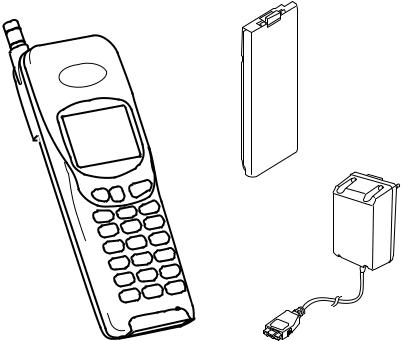
2.2 Handportable Main Kit
The handportable main kit provides a standalone class 4 GSM telephone. The plug-in SIM contains the subscriber and network information necessary to operate the phone on a GSM network.
2
1
3
Figure 1: Handportable Main Unit Kit |
500-0201 |
IDENTIFICATION NUMBER |
DESCRIPTION |
PART NUMBER |
|
|
|
1 |
Main unit |
EB-G500 |
|
|
|
2 |
Battery |
EB-BM500 |
|
|
|
3 |
Adaptor |
EB-CA400 UK/EU/SA/TH |
|
|
|
— |
Operating instructions |
ZD71348A |
|
|
|
MCUK960901C8 |
Section 2 |
Issue 1 |
Service Manual |
2 - 1 |
Revision 0 |
GENERAL DESCRIPTION
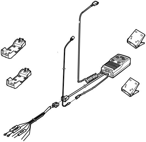
2.3 Handsfree Car Mount Kit
The handsfree car mount kit enables the handportable to be mounted in a vehicle, and to operate in handsfree mode.
The handsfree unit contains a speaker, with separate volume control. Speech is via a microphone mounted on the dashboard or the sun visor.
The handsfree unit also provides external power for the handheld internal charger.
2 |
4 |
6 |
1
3
5
7
Figure 2: Handsfree Car Mount Kit |
500-0202 |
IDENTIFICATION NUMBER |
DESCRIPTION |
PART NUMBER |
|
|
|
1 |
Handsfree unit |
EB-HF400 |
|
|
|
2 |
Holder – G350/G400 |
EB-KA400 |
|
|
|
3 |
Holder – G500 |
EB-KA500 |
|
|
|
4 |
Handsfree microphone |
EBM1177 |
|
|
|
5 |
Adjustable angle bracket |
EBN0001 |
|
|
|
6 |
Adjustable angle bracket |
EBN0002 |
|
|
|
7 |
Power supply cable |
EBW70090 |
|
|
|
Issue 1 |
Section 2 |
MCUK960901C8 |
Revision 0 |
2 - 2 |
Service Manual |
GENERAL DESCRIPTION
2.4 Holder Kit
The holder kit allows convenient mounting of the telephone in a vehicle. In conjunction with the DC adaptor this can make a simple car mount kit. The adjustable angle bracket and telephone holder are attached to a convenient fixing point in the vehicle.
1
2
Figure 3: Holder Kit |
500-0204 |
IDENTIFICATION NUMBER |
DESCRIPTION |
PART NUMBER |
|
|
|
1 |
Holder |
EB-KA500 |
|
|
|
2 |
Adjustable angle bracket |
EBN0002 |
|
|
|
2.5 DC Adaptor
The DC adaptor kit enables the handportable unit to be powered from a vehicle battery, provided that the vehicle has a cigar lighter socket.
One end of the DC adaptor plugs into the handportable with the telephone battery connected. The other end of the adaptor is pushed into the cigar lighter socket.
1 

Figure 4: DC Adaptor |
500-0203 |
IDENTIFICATION NUMBER |
DESCRIPTION |
PART NUMBER |
|
|
|
1 |
DC Adaptor unit |
EB-CD400A |
|
|
|
MCUK960901C8 |
Section 2 |
Issue 1 |
Service Manual |
2 - 3 |
Revision 0 |
GENERAL DESCRIPTION
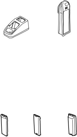
2.6 Dual Charger and Carry Case
The dual charger has two charging slots, enabling the telephone battery to be charged individually or as a part of the whole telephone assembly.
2
1
Figure 5: Dual Charger and Carry Case |
500-0205 |
IDENTIFICATION NUMBER |
DESCRIPTION |
PART NUMBER |
|
|
|
1 |
Dual charger |
EB-CR500 |
|
|
|
2 |
Carry case |
EB-YK400 |
|
|
|
2.7 Battery Packs
There are three battery packs, all of which use Ni-MH. The Battery Pack (S) is 600mAh; the Battery Pack (M) is 850mAh and the Battery Pack (XL) is 1600mAh.
1 |
2 |
3 |
Figure 6: Battery Packs |
500-0206 |
IDENTIFICATION NUMBER |
DESCRIPTION |
PART NUMBER |
|
|
|
1 |
Battery Pack (S) |
EB-BS500 |
|
|
|
2 |
Battery Pack (M) |
EB-BM500 |
|
|
|
3 |
Battery Pack (XL) |
EB-BX500 |
|
|
|
Issue 1 |
Section 2 |
MCUK960901C8 |
Revision 0 |
2 - 4 |
Service Manual |
GENERAL DESCRIPTION
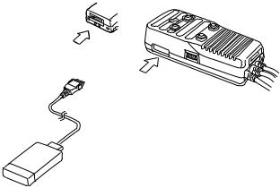
2.8 PCMCIA Interface Card
The PCMCIA interface card is used with the handportable and a laptop personal computer to provide a PC fax and modem facility.
3
2
1
Figure 7: PCMCIA Card |
500-0207 |
IDENTIFICATION NUMBER |
DESCRIPTION |
PART NUMBER |
|
|
|
|
|
1 |
PCMCIA Interface card |
EB-PA400 |
|
|
|
|
|
2 |
Handsfree unit |
— |
|
– connection |
|||
|
|
||
|
|
|
|
3 |
Telephone |
— |
|
– connection |
|||
|
|
||
|
|
|
MCUK960901C8 |
Section 2 |
Issue 1 |
Service Manual |
2 - 5 |
Revision 0 |
GENERAL DESCRIPTION
2.8 Kit Composition
UNIT NAME AND NUMBER |
KIT CONTENTS |
|
|
||
|
|
|
|
|
|
|
EB-G500 |
Main Unit |
|
|
|
|
EB-BM500 |
Battery Pack (M) |
|
||
Main Unit Kit |
EB-CA400 |
AC Adaptor (‘EU’, ‘SA’, ‘TH’ or ‘UK’) |
|||
ZD70052C |
GSM Network Codes and Names |
||||
|
|||||
|
and at least one operating instruction, quick reference and |
||||
|
quick start from below. |
|
|
||
|
|
|
|
|
|
|
Arabic |
ZD71411A |
Chinese |
ZD71412A |
|
|
Czech |
ZD71496A |
Danish |
ZD71349A |
|
|
Dutch |
ZD71350A |
English |
ZD71348A |
|
|
Finnish |
ZD71351A |
French |
ZD71352A |
|
Operating Instructions |
German |
ZD71353A |
Greek |
ZD71354A |
|
Hungarian |
ZD71497A |
Italian |
ZD71355A |
||
|
|||||
|
Norwegian |
ZD71356A |
Polish |
ZD71498A |
|
|
Portuguese |
ZD71357A |
Russian |
ZD71495A |
|
|
Spanish |
ZD71358A |
Swedish |
ZD71359A |
|
|
Turkish |
ZD71360A |
|
|
|
|
|
|
|
|
|
|
Arabic |
ZD71413A |
Chinese |
ZD71414A |
|
|
Czech |
ZD71500A |
Danish |
ZD71362A |
|
|
Dutch |
ZD71363A |
English |
ZD71361A |
|
|
Finnish |
ZD71364A |
French |
ZD71365A |
|
Quick Reference |
German |
ZD71366A |
Greek |
ZD71367A |
|
Hungarian |
ZD71501A |
Italian |
ZD71368A |
||
|
|||||
|
Norwegian |
ZD71369A |
Polish |
ZD71502A |
|
|
Portuguese |
ZD71370A |
Russian |
ZD71499A |
|
|
Spanish |
ZD71371A |
Swedish |
ZD71372A |
|
|
Turkish |
ZD71373A |
|
|
|
|
|
|
|
|
|
|
Arabic |
ZD71428A |
Chinese |
ZD71429A |
|
|
Czech |
ZD71504A |
Danish |
ZD71416A |
|
|
Dutch |
ZD71417A |
English |
ZD71415A |
|
|
Finnish |
ZD71419A |
French |
ZD71418A |
|
Quick Start |
German |
ZD71420A |
Greek |
ZD71421A |
|
Hungarian |
ZD71505A |
Italian |
ZD71422A |
||
|
|||||
|
Norwegian |
ZD71423A |
Polish |
ZD71506A |
|
|
Portuguese |
ZD71424A |
Russian |
ZD71503A |
|
|
Spanish |
ZD71425A |
Swedish |
ZD71426A |
|
|
Turkish |
ZD71427A |
|
|
|
|
|
|
|
|
|
|
EB-HF400 |
H/F Unit |
|
|
|
|
EB-KA400 |
Holder – G350/G400 |
|
||
Car Mount Kit |
EB-KA500 |
Holder – G500 |
|
|
|
EBM1177 |
Microphone |
|
|
||
EB-HF400Z |
|
|
|||
EBN0001 |
AA Bracket |
|
|
||
|
|
|
|||
|
EBN0002 |
AA Bracket 2 |
|
|
|
|
EBW70090 |
Power Supply Cable |
|
||
|
|
|
|
|
|
Holder Kit |
EB-KA500 |
Holder |
|
|
|
EB-KA500Z |
EBN0002 |
AA Bracket 2 |
|
|
|
|
|
|
|
|
|
|
EB-CD400A |
DC Adaptor |
|
|
|
|
EB-CR500 |
Dual Charger |
|
|
|
|
EB-YK400 |
Carry Case |
|
|
|
Other Optional Accessories |
EB-BS500 |
Battery Pack (S) |
|
||
EB-BM500 |
Battery Pack (M) |
|
|||
|
|
||||
|
EB-BX500 |
Battery Pack (XL) |
|
||
|
EB-PA400 |
PCMCIA Data Interface Card |
|
||
|
EB-CA400 |
AC Adaptor |
|
|
|
|
|
|
|
|
|
Issue 1 |
Section 2 |
MCUK960901C8 |
Revision 0 |
2 - 6 |
Service Manual |
OPERATING INSTRUCTIONS
3 OPERATING INSTRUCTIONS
3.1 General
This section provides a brief guide to the operation and facilities available on the G500 handportable unit. Refer to the Operating Instructions for full operational information.
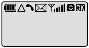
3.2 LCD Display
The G500 handportable unit has a 3 line by 12 character chip on glass liquid crystal display in conjunction with the following icons:
Figure 1: LCD display |
500-0301 |
|
Displays the battery charge level: |
|
|
H Battery is at full charge. |
|
H |
K Battery requires recharging. |
|
|
G The battery icon flashes during charging. |
|
|
During car mount use, when the battery is fully charged, the battery icon will not light. |
|
|
|
|
T |
Indicates that you are registered on a non-home network. |
|
|
|
|
N |
Indicates that a call is in progress or flashes when a call is on hold. |
|
|
|
|
W |
Indicates the reception of a short text message from the Short Message Service (SMS). |
|
This icon will flash when a message has not been read. |
||
|
||
|
|
|
A |
Indicates that it is possible to make an emergency call. |
|
|
|
|
|
Indicates received signal strength: |
|
R |
AR Strong signal area. |
|
|
AY Weak signal area. |
|
|
|
|
v |
Indicates that the V and U keys can be pressed. |
|
|
|
|
o |
Indicates that the O key can be pressed. |
|
|
|
Following some operations the display will automatically clear after three seconds or after pressing any key except E.
The display will also show other symbols that will indicate which key can be pressed next or the current setting of a function:
` The S key can be pressed or this is the active call when there are two calls. » This is the held call when there are two calls.
> This is the current setting for the chosen function. ¼ The P key can be pressed.
F:a{}A Pressing the F key will toggle between upper and lower case.
MCUK960901C8 |
Section 3 |
Issue 1 |
Service Manual |
3 - 1 |
Revision 0 |
OPERATING INSTRUCTIONS
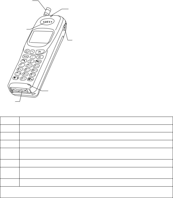
3.3 Location of Controls
Antenna |
Incomming/Charge |
Incoming/Charge indicator: |
|
indicator |
|
|
Green – incoming call. |
|
|
|
|
|
|
Red – charging battery pack. |
Earpiece
Display |
Vibration alert |
|
|
|
switch |
Microphone
Extrenal connector
Vibration alert switch:
ON – telephone will vibrate with an incoming call. OFF – telephone will ring with an incoming call.
External connector:
Used to connect to external accessories or charging equipment.
Figure 2: Location of controls for G500 |
500-0302 |
V and U Increases or decreases volume, scrolls through options or function menu.
OEnters data, selects an option or confirms an action.
MRecords or plays back voice memo.
FEnters function menu or changes between upper and lower case letters.
PRecalls memory, accesses short messages, displays the rest of a telephone number or name tag when pressed and held.
SMakes a call.
CClears the last digit entered, clears all digits when pressed and held or returns to the previous display.
EEnds a call or switches the telephone on/off when pressed and held.
Digit keys 0 to 9, * and #. Where appropriate the 0 key will enter the international access code “+”, wild numbers or pauses when pressed and held.
Issue 1 |
Section 3 |
MCUK960901C8 |
Revision 0 |
3 - 2 |
Service Manual |
OPERATING INSTRUCTIONS
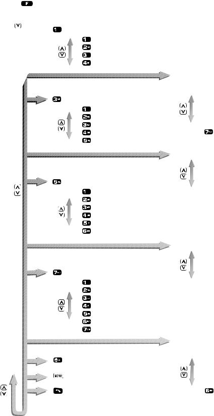
3.4 G500 Function Menu Structure
 Call bar
 All outgoing
 Outgoing international
 Outgoing international except home
 All incoming
 Incoming while roaming
 Status
New password
 Call waiting
 Set call waiting
 Status
 Networks
 Manual network selection
 Preferred network list
 My telephone number
 Security
 Lock level
 New lock code
 PIN on/off
 New PIN
 New PIN2
Fixed dial
Figure 3: Function menu |
400-0640 |
MCUK960901C8 |
Section 3 |
Issue 1 |
Service Manual |
3 - 3 |
Revision 0 |
OPERATING INSTRUCTIONS
3.5 Basic Operation
FUNCTION |
KEY OPERATION |
|
|
To switch ON/OFF |
E and hold |
|
|
To receive a telephone call |
Any key except E |
|
|
To make a telephone call: |
|
Manually |
Telephone number + S |
|
|
From memory |
P followed by phone book number + S |
|
|
|
|
To clear misdialled digit(s): |
|
Last digit |
C |
All digits |
C and hold |
|
|
To check overflow digits |
P and hold |
|
|
To redial last number: |
|
Last dialled number |
S S |
Other number in last dialled number list |
S V or U S |
|
|
To adjust volume: |
|
Key volume – during standby |
U to increase, V to decrease |
Ear volume – during a call |
U to increase, V to decrease |
Ring volume |
F 7 2, U to increase, V to decrease |
|
|
To end a telephone call |
E |
|
|
Emergency calls |
112 + S |
|
|
Store a telephone number in memory |
telephone number + P |
|
|
Recall a number from memory |
P – the display must not show any numbers |
|
|
Issue 1 |
Section 3 |
MCUK960901C8 |
Revision 0 |
3 - 4 |
Service Manual |
OPERATING INSTRUCTIONS
3.6 Troubleshooting
The user is given the following information and advised to contact the dealer if the problems persist:
Problem |
Causes and Solutions |
|
|
|
|
Telephone will |
Check that the battery pack is fully charged and correctly connected to the telephone. |
|
not switch on |
||
|
||
|
|
|
|
Battery life is affected by the network you are using and the condition of the battery pack. |
|
|
The life of the battery pack is affected by improper charging, this is inherent in all Ni-MH and |
|
Short battery life |
Ni-Cd batteries. To maintain maximum performance always use until the low battery warning |
|
and then fully recharge the battery pack. To revive the battery pack use the telephone until it |
||
|
||
|
switches off and then fully recharge three times. However, the battery pack will eventually |
|
|
wear out and must be replaced with a new one. |
|
|
|
|
Battery level |
If a battery is deeply discharged it will take a short time before there is sufficient power in the |
|
indicator (H) |
telephone to display the battery level indicator (H). |
|
does not light |
The battery pack must be charged in a temperature no lower than +5°C and no higher than |
|
when charging |
+35°C. |
|
|
|
|
Calls cannot be |
Calls cannot be made when the telephone is locked or outgoing calls are barred. |
|
Check that the telephone is registered to a network. Move to a coverage area and operate |
||
made |
||
your telephone after it has registered with a network. |
||
|
||
|
|
|
Calls cannot be |
Check the telephone number is stored in Fixed Dial Memory or your SIM supports Fixed Dial |
|
made from Fixed |
||
Memory. |
||
Dial Memory |
||
|
||
|
|
|
Calls cannot be |
To receive a call the telephone must be switched on. |
|
received |
Calls cannot be received when incoming calls are barred. |
|
|
|
|
Emergency calls |
Check that the antenna symbol A is displayed. Move to a coverage area and operate your |
|
cannot be made |
telephone when the antenna symbol is displayed. |
|
|
|
|
Telephone |
|
|
numbers cannot |
Memory cannot be recalled when the telephone is fully locked or “Fixed Dial” is switched on. |
|
be recalled |
|
|
|
|
3.7 Error Messages
The following table is a list of error messages that may occur during use of the telephone, with a description and suggested course of action:
AREA NOT |
Roaming in the selected area is not allowed. |
|
ALLOWED |
||
|
||
|
|
|
BLACKLIST |
Blacklist of unsuccessfully dialled numbers is full. Switch the telephone off and then on |
|
FULL |
again. Telephone numbers are removed from the blacklist after twenty-four hours. |
|
|
|
|
INVALID SIM |
Your SIM cannot be used in the telephone. The telephone may be personalised to a |
|
particular SIM or network. Contact your service provider. |
||
|
||
|
|
|
LOCK CODE |
A wrong lock code has been entered. Re-enter the correct lock code. |
|
INVALID |
||
|
||
|
|
|
LOW BATTERY |
The battery power is low. Replace with a fully recharged battery pack or recharge the battery |
|
pack. |
||
|
||
|
|
|
MESSAGE |
A message has been received but the message area is full. To receive messages delete |
|
REJECTED |
some of the currently stored messages or set messages to automatically clear. |
|
|
|
MCUK960901C8 |
Section 3 |
Issue 1 |
Service Manual |
3 - 5 |
Revision 0 |
OPERATING INSTRUCTIONS
NETWORK |
The message sent has failed because of a network error. Check that the Message Centre |
|
ERROR |
number is correct or wait for a short while and retry. |
|
|
|
|
NETWORK NOT |
Roaming with the selected network is not allowed. |
|
ALLOWED |
||
|
||
|
|
|
NETWORK |
The supplementary service requested has been rejected by the network because of a system |
|
REJECTED |
failure. Wait for a short while and retry. |
|
|
|
|
NO SIM |
The telephone has not detected a SIM. If a SIM is present remove and then replace it and |
|
PRESENT |
make sure that the SIM holder is locked shut. |
|
|
|
|
NOT ALLOWED |
The entered security code is too short. Enter an appropriate security code. |
|
|
|
|
TEL. NUMBER |
The memory capacity for storing overflow digits in your SIM is full. You cannot enter more |
|
TOO LONG |
than twenty digits until some of the overflow telephone numbers stored in memory are |
|
MAX = 20 |
deleted. |
|
|
|
|
PASSWORD |
A wrong password has been entered. Enter the correct password. |
|
INVALID |
||
|
||
|
|
|
PIN BLOCKED/ |
The PIN/PIN2 is blocked because the wrong number has been entered three times. The |
|
telephone will ask you to enter the PUK/PUK2 then you will have to enter a new PIN/PIN2. |
||
PIN2 BLOCKED |
||
The PUK/PUK2 is supplied by your service provider. |
||
|
||
|
|
|
PIN INVALID/ |
A wrong PIN/PIN2 has been entered. Enter the correct PIN/PIN2. |
|
PIN2 INVALID |
||
|
||
|
|
|
PIN2 |
The PIN2 is blocked permanently because the wrong PUK2 has been entered ten times. |
|
INVALIDATED |
Supplementary services controlled by PIN2 cannot be used. Contact your service provider. |
|
|
|
|
PLEASE RETRY |
The supplementary service requested has failed. Wait for a short while and retry. |
|
|
|
|
PUK INVALID/ |
A wrong PUK/PUK2 has been entered. Enter the correct PUK/PUK2. |
|
PUK2 INVALID |
||
|
||
|
|
|
SECURITY |
The network has detected authentication failure because your SIM is not registered with that |
|
FAILURE |
network. Contact your service provider. |
|
|
|
|
SIM BLOCKED |
The SIM is blocked because the wrong PUK has been entered ten times. Contact your |
|
service provider. |
||
|
||
|
|
|
SIM ERROR |
The telephone has detected a problem with the SIM. Switch the telephone off and then back |
|
on. If the message does not disappear contact your service provider. |
||
|
||
|
|
|
STORE FULL |
Phone Book/Fixed Dial Memory is full. Delete an entry or overwrite old information. |
|
|
|
|
SUBSCRIPTION |
The supplementary service requested has been revoked because the wrong password has |
|
REVOKED |
been entered four times. Contact your service provider. |
|
|
|
|
VACANT |
There is no information in the memory location that you selected. To clear this display press |
|
C. |
||
|
||
|
|
|
XX XXXXX X |
There is a permanent error in the telephone. Switch the telephone off and then back on. If |
|
XXXX |
the message re-appears, contact your dealer. |
|
|
|
Issue 1 |
Section 3 |
MCUK960901C8 |
Revision 0 |
3 - 6 |
Service Manual |
OPERATING INSTRUCTIONS
3.8 Security Codes
CODE TYPE |
NUMBER OF |
DESCRIPTION |
|
DIGITS |
|||
|
|
||
|
|
|
|
Personal Identification |
4 to 8 |
Controls SIM security. Supplied by the service provider. |
|
Number (PIN) |
|||
|
|
||
|
|
|
|
PIN 2 |
4 to 8 |
Controls memory security. Supplied by the service provider. |
|
|
|
|
|
|
|
Used to unblock PIN and PIN 2. A PIN or PIN 2 will become |
|
PIN/PIN 2 Unblocking Key |
|
blocked if the wrong PIN or PIN 2 is entered three times. |
|
8 |
When the blocked PIN or PIN 2 is unblocked, a new PIN or |
||
(PUK/PUK 2) |
PIN 2 must be entered. If the wrong PUK or PUK 2 is entered |
||
|
|||
|
|
10 times, your SIM will be unusable. |
|
|
|
Supplied by the service provider. |
|
|
|
|
|
|
|
Controls the call bar function. If the wrong password is |
|
Password |
4 |
entered three times, this service will be revoked. Supplied by |
|
|
|
the service provider. |
|
|
|
|
|
Lock Code |
4 |
Controls telephone security. |
|
Factory set to “0000”. |
|||
|
|
||
|
|
|
MCUK960901C8 |
Section 3 |
Issue 1 |
Service Manual |
3 - 7 |
Revision 0 |
OPERATING INSTRUCTIONS
3.9 GSM Services Supported by PCMCIA Card
Bearer |
|
Access |
|
Information |
Error |
|
Service |
Bearer Service Rate |
Access Rate |
Correction |
|||
Structure |
Transfer |
|||||
Number |
|
|
Options |
|||
|
|
|
|
|||
|
|
|
|
|
|
|
21 |
Asynchronous 300 bps |
Asynch |
300 bps |
UDI or |
T or NT |
|
modem |
||||||
|
|
|
|
|
||
|
|
|
|
|
|
|
22 |
Asynchronous 1.2 kbps |
Asynch |
1.2 kbps |
UDI or |
T or NT |
|
modem |
||||||
|
|
|
|
|
||
|
|
|
|
|
|
|
23 |
Asynchronous 1200/75 bps |
Asynch |
1200/75 bps |
UDI or |
T or NT |
|
modem |
||||||
|
|
|
|
|
||
|
|
|
|
|
|
|
24 |
Asynchronous 2.4 kbps |
Asynch |
2.4 kbps |
UDI or |
T or NT |
|
modem |
||||||
|
|
|
|
|
||
|
|
|
|
|
|
|
25 |
Asynchronous 4.8 kbps |
Asynch |
4.8 kbps |
UDI or |
T or NT |
|
modem |
||||||
|
|
|
|
|
||
|
|
|
|
|
|
|
26 |
Asynchronous 9.6 kbps |
Asynch |
9.6 kbps |
UDI or |
T or NT |
|
modem |
||||||
|
|
|
|
|
||
|
|
|
|
|
|
|
41 |
Dedicated PAD Access 300 |
Asynch |
300 bps |
UDI |
T or NT |
|
bps |
||||||
|
|
|
|
|
||
|
|
|
|
|
|
|
42 |
Dedicated PAD Access 1.2 |
Asynch |
1.2 kbps |
UDI |
T or NT |
|
kbps |
||||||
|
|
|
|
|
||
|
|
|
|
|
|
|
44 |
Dedicated PAD Access 2.4 |
Asynch |
2.4 kbps |
UDI |
T or NT |
|
kbps |
||||||
|
|
|
|
|
||
|
|
|
|
|
|
|
45 |
Dedicated PAD Access 4.8 |
Asynch |
4.8 kbps |
UDI |
T or NT |
|
kbps |
||||||
|
|
|
|
|
||
|
|
|
|
|
|
|
46 |
Dedicated PAD Access 9.6 |
Asynch |
9.6 kbps |
UDI |
T or NT |
|
kbps |
||||||
|
|
|
|
|
||
|
|
|
|
|
|
UDI = Unrestricted Digital Information
T = Transparent (non-error corrected)
NT = Non-Transparent (error corrected)
AT commands to select these services are: +CBST, /N and +CIWF.
Issue 1 |
Section 3 |
MCUK960901C8 |
Revision 0 |
3 - 8 |
Service Manual |
OPERATING INSTRUCTIONS
3.10 GSM Network Codes and Names
Country |
Access |
Network |
|
|
|
|
|
|
|
|
|
|
|||
Code |
Operator |
Name |
Abbreviation |
Code |
|
||
|
|
||||||
|
|
|
|||||
|
|
|
|
|
|
|
|
AND |
+37 |
STA ANDORRA |
MOBILAND |
M-AND |
213 |
03 |
|
|
|
|
|
|
|
|
|
AUS |
+61 |
TELECOM Australia |
MOBILENET |
M-NET |
505 |
01 |
|
|
|
|
|
|
|
|
|
AUS |
+61 |
OPTUS Communications Pty Ltd. |
OPTUS |
OPTUS |
505 |
02 |
|
Mobile |
|||||||
|
|
|
|
|
|
||
|
|
|
|
|
|
|
|
AUS |
+61 |
Vodafone PTY |
VODAFONE |
VFONE |
505 |
03 |
|
|
|
|
|
|
|
|
|
A |
+43 |
PTV Austria |
A1 |
A1 |
232 |
01 |
|
|
|
|
|
|
|
|
|
BEL |
+32 |
Belgacom Mobile |
PROXIMUS |
PROXI |
206 |
01 |
|
|
|
|
|
|
|
|
|
BG |
+359 |
MOBILTEL AD |
CITRON GSM |
CITRON |
284 |
01 |
|
|
|
|
|
|
|
|
|
BHR |
+973 |
BAHREIN Telecommunications Co. |
MOBILE |
M.PLUS |
426 |
01 |
|
PLUS |
|||||||
|
|
|
|
|
|
||
|
|
|
|
|
|
|
|
CH |
+41 |
Swiss Telecom PTT |
NATEL D |
NAT D |
228 |
01 |
|
GSM |
|||||||
|
|
|
|
|
|
||
|
|
|
|
|
|
|
|
CHN |
+86 |
China United Telecommuni-cations |
CHINA |
CU-GSM |
460 |
01 |
|
Corporation |
UNICOM |
||||||
|
|
|
|
|
|||
|
|
|
|
|
|
|
|
CY |
+357 |
Cyprus Telecommunication Authority |
CYTAGSM |
CY-GSM |
280 |
01 |
|
|
|
|
|
|
|
|
|
D |
+49 |
DeTeMobil GmbH |
Mobilfunk D1 |
D1 |
262 |
01 |
|
|
|
|
|
|
|
|
|
D |
+49 |
Mannesmann Mobilfunk |
D2 PRIVAT |
D2 |
262 |
02 |
|
|
|
|
|
|
|
|
|
E |
+34 |
TELEFONICA MOVILES |
MOVISTAR |
MSTAR |
214 |
07 |
|
|
|
|
|
|
|
|
|
E |
+34 |
AIRTEL SPAIN |
AIRTEL |
AIRTL |
214 |
01 |
|
|
|
|
|
|
|
|
|
EE |
+372 |
Eesti Mobiiltelefon |
EMT GSM |
EMT |
248 |
01 |
|
|
|
|
|
|
|
|
|
EE |
+372 |
RADIOLINJA EESTI AS |
EESTI |
RLE |
248 |
02 |
|
|
|
|
|
|
|
|
|
DK |
+45 |
TELE Danmark Mobile |
TDK-MOBIL |
TD MOB |
238 |
01 |
|
|
|
|
|
|
|
|
|
DK |
+45 |
Dansk Mobil Telefon DMT |
SONOFON |
SONO |
238 |
02 |
|
|
|
|
|
|
|
|
|
F |
+33 |
France Telecom |
Itineris |
Itine |
208 |
01 |
|
|
|
|
|
|
|
|
|
F |
+33 |
SFR |
SFR |
SFR |
208 |
10 |
|
|
|
|
|
|
|
|
|
F |
+33 |
SRR |
SFR |
SFR RU |
647 |
10 |
|
REUNION |
|||||||
|
|
|
|
|
|
||
|
|
|
|
|
|
|
|
F |
+33 |
TIKIPHONE |
VINI |
VINI |
547 |
20 |
|
|
|
|
|
|
|
|
|
FI |
+358 |
Telecom Finland |
TELECOM |
TELE |
244 |
91 |
|
FIN |
|||||||
|
|
|
|
|
|
||
|
|
|
|
|
|
|
|
FI |
+358 |
OY Radiolinja AB |
RADIOLINJA |
RL |
244 |
05 |
|
|
|
|
|
|
|
|
|
GIB |
+350 |
GIBTEL |
GIBTEL |
GIBTEL |
266 |
01 |
|
|
|
|
|
|
|
|
|
GR |
+30 |
Panafon S.A |
PANAFON |
PAN |
202 |
05 |
|
|
|
|
|
|
|
|
|
GR |
+30 |
STET HELLAS |
TELESTET |
TLSTET |
202 |
10 |
|
|
|
|
|
|
|
|
|
H |
+36 |
Westel 900 GSM RT |
WESTEL 900 |
W-900 |
216 |
30 |
|
|
|
|
|
|
|
|
MCUK960901C8 |
Section 3 |
Issue 1 |
Service Manual |
3 - 9 |
Revision 0 |
OPERATING INSTRUCTIONS
Country |
Access |
Network |
|
|
|
|
|
|
|
|
|
|
|
||
Code |
Operator |
Name |
|
Abbreviation |
Code |
|
|
|
|
|
|||||
|
|
|
|
||||
|
|
|
|
|
|
|
|
H |
+36 |
Pannon GSM RT |
PANNON |
|
PANNON |
216 |
01 |
GSM |
|
||||||
|
|
|
|
|
|
|
|
|
|
|
|
|
|
|
|
HK |
+852 |
Hong Kong Telecom CSL Ltd. |
TCSL GSM |
|
TCSL |
454 |
00 |
|
|
|
|
|
|
|
|
HK |
+852 |
Hutchison Telephone Co. Ltd. |
HTCLGSM |
|
HTCL |
454 |
04 |
|
|
|
|
|
|
|
|
HK |
+852 |
SmarTone Mobile Communications Ltd. |
SMARTONE |
|
HKSMC |
454 |
06 |
|
|
|
|
|
|
|
|
HR |
+95 |
HPT |
CRONET |
|
CRON |
219 |
01 |
|
|
|
|
|
|
|
|
I |
+39 |
OMNITEL PRONTO ITALIA |
OMNITEL |
|
OMNI |
222 |
10 |
|
|
|
|
|
|
|
|
I |
+39 |
TELECOM ITALIA MOBILE |
ITALIA |
|
TIM |
222 |
01 |
MOBILE |
|
||||||
|
|
|
|
|
|
|
|
|
|
|
|
|
|
|
|
INA |
+91 |
Bharti Cellular Limited |
AirTel |
|
AIRTL |
404 |
10 |
|
|
|
|
|
|
|
|
INA |
+91 |
BPL SYSTEMS & PROJECTS LTD. INDIA |
BPL - MOBILE |
|
BPL |
404 |
21 |
|
|
|
|
|
|
|
|
IND |
+62 |
PT Telekomunikasi Indonesia |
TELKOMSEL |
|
T-SEL |
510 |
10 |
|
|
|
|
|
|
|
|
IND |
+62 |
PT. SATELIT PALAPA INDONESIA |
SATELINDOCE |
|
SAT-C |
510 |
01 |
|
|
|
L |
|
|
|
|
IND |
+62 |
PT EXCELCOMINDO PRATAMA |
EXCELCOM |
|
EX-CEL |
510 |
11 |
|
|
|
|
|
|
|
|
IRL |
+353 |
Telecom Ireland |
EIRCELL-GSM |
|
E-GSM |
272 |
01 |
|
|
|
|
|
|
|
|
KSA |
+966 |
ELECTRONIC APPLICATIONS |
EAE-ALJAWW |
|
EAE |
420 |
07 |
|
|
ESTABLISHMENT |
AL |
|
|
|
|
KT |
+96 |
Mobile Telecommunications Co. |
MTCNet |
|
MTC |
419 |
02 |
|
|
|
|
|
|
|
|
L |
+352 |
P & T Luxembourg |
LUXGSM |
|
P&T L |
270 |
01 |
|
|
|
|
|
|
|
|
LV |
+371 |
Latvian Mobile Telephone Co.Ltd. |
LMT GSM |
|
LMT |
247 |
01 |
|
|
|
|
|
|
|
|
MAC |
+853 |
C.T.M. |
TELEMOVEL+ |
|
CTMGSM |
455 |
01 |
|
|
|
|
|
|
|
|
MOR |
+212 |
ONPT MOROCCO |
ONPT |
|
ONPT |
604 |
01 |
|
|
|
|
|
|
|
|
MRU |
+60 |
MAURITIUS TELECOM LTD. |
CELLPLUS |
|
CELL + |
617 |
01 |
|
|
|
|
|
|
|
|
MY |
+60 |
BINARIANG COMMUNICATIONS SDN |
maxis mobile |
|
maxis |
502 |
12 |
BHD. |
|
||||||
|
|
|
|
|
|
|
|
|
|
|
|
|
|
|
|
N |
+47 |
Telenor Mobil AS |
Telenor Mobil |
|
Tele N |
242 |
01 |
|
|
|
|
|
|
|
|
N |
+47 |
NetCom GSM A/S |
NetCom GSM |
|
N COM |
242 |
02 |
|
|
|
|
|
|
|
|
NL |
+31 |
LIBERTEL |
LIBERTEL |
|
LIBTEL |
204 |
04 |
|
|
|
|
|
|
|
|
NL |
+31 |
PTT Telecom |
PTT |
|
NL PTT |
204 |
08 |
TELECOM |
|
||||||
|
|
|
|
|
|
|
|
|
|
|
|
|
|
|
|
NZ |
+64 |
BELLSOUTH |
BELLSOUTH |
|
BSNZ |
530 |
01 |
|
|
|
|
|
|
|
|
P |
+351 |
Telecomunicaçoes Moveis Nacionais |
TMN |
|
TMN |
268 |
06 |
(TMN) |
|
||||||
|
|
|
|
|
|
|
|
|
|
|
|
|
|
|
|
P |
+351 |
TELECEL |
TELECEL |
|
TLCL |
268 |
01 |
|
|
|
|
|
|
|
|
PH |
+63 |
Globe Telecom GMCR Inc |
Globe |
|
GLOBE |
515 |
02 |
Telecom |
|
||||||
|
|
|
|
|
|
|
|
|
|
|
|
|
|
|
|
Issue 1 |
Section |
3 |
MCUK960901C8 |
Revision 0 |
3 - 10 |
|
Service Manual |
OPERATING INSTRUCTIONS
Country |
Access |
Network |
|
|
|
|
|
|
|
|
|
|
|||
Code |
Operator |
Name |
Abbreviation |
Code |
|
||
|
|
||||||
|
|
|
|||||
|
|
|
|
|
|
|
|
PH |
+63 |
Isla Communications Co. Inc. |
Islacom |
ISLA |
515 |
01 |
|
|
|
|
|
|
|
|
|
QAT |
+974 |
Q-TEL |
QATARNET |
Q-NET |
427 |
01 |
|
|
|
|
|
|
|
|
|
ROC |
+886 |
LDTA |
LDTA GSM |
LDGSM |
466 |
92 |
|
|
|
|
|
|
|
|
|
RL |
+961 |
Telecom Finland International |
LibanCell |
LibCL |
415 |
03 |
|
|
|
|
|
|
|
|
|
RUS |
+701 |
Mobile Telesystems |
MTS |
MTS |
250 |
01 |
|
|
|
|
|
|
|
|
|
RUS |
+701 |
North-West GSM |
North-West |
NWGSM |
250 |
02 |
|
GSM |
|||||||
|
|
|
|
|
|
||
|
|
|
|
|
|
|
|
S |
+46 |
Telia Mobitel |
TELIA |
TELIA |
240 |
01 |
|
MOBITEL |
|||||||
|
|
|
|
|
|
||
|
|
|
|
|
|
|
|
S |
+46 |
COMVIQ GSM AB |
COMVIQ |
IQ |
240 |
07 |
|
|
|
|
|
|
|
|
|
S |
+46 |
EUROPOLITAN AB |
EUROPOLITAN |
EURO |
240 |
08 |
|
|
|
|
|
|
|
|
|
SA |
+27 |
VODACOM |
VodaCom |
VODA |
655 |
01 |
|
|
|
|
|
|
|
|
|
SA |
+27 |
Mobile Telephone Networks |
MTN |
MTN |
655 |
10 |
|
|
|
|
|
|
|
|
|
SGP |
+65 |
Singapore Telecom |
ST-GSM |
STGSM |
525 |
01 |
|
|
|
|
|
|
|
|
|
SRI |
+94 |
MTN NETWORKS (PVT) SRI LANKA |
DIALOG |
DALOG |
413 |
02 |
|
|
|
|
|
|
|
|
|
SYR |
+963 |
Mobile Syria |
MOBILE |
SYR MOB |
417 |
09 |
|
SYRIA |
|||||||
|
|
|
|
|
|
||
|
|
|
|
|
|
|
|
TH |
+66 |
Advanced Info Service Public Company |
AIS GSM |
TH AIS |
520 |
01 |
|
Limited |
|||||||
|
|
|
|
|
|
||
|
|
|
|
|
|
|
|
TR |
+90 |
PTT Turkey |
TURKCELL |
TCELL |
286 |
01 |
|
GSM |
|||||||
|
|
|
|
|
|
||
|
|
|
|
|
|
|
|
TR |
+90 |
PTT Turkey |
PTT TELSIM |
TLSIM |
286 |
02 |
|
GSM |
|||||||
|
|
|
|
|
|
||
|
|
|
|
|
|
|
|
UAE |
+971 |
ETISALAT |
ETISALAT |
ETSLT |
424 |
02 |
|
|
|
|
|
|
|
|
|
UK |
+44 |
Cellnet |
CELLNET |
CLNET |
234 |
10 |
|
|
|
|
|
|
|
|
|
UK |
+44 |
GUERNSEY TELECOMS |
GUERNSEY |
GSY-TEL |
234 |
55 |
|
TEL |
|||||||
|
|
|
|
|
|
||
|
|
|
|
|
|
|
|
UK |
+44 |
Jersey Telecoms |
Jersey Tele |
JER1 |
234 |
50 |
|
|
|
|
|
|
|
|
|
UK |
+44 |
MANX TELECOM |
PRONTO |
MANX |
234 |
58 |
|
GSM |
|||||||
|
|
|
|
|
|
||
|
|
|
|
|
|
|
|
UK |
+44 |
Vodafone |
VODAFONE |
VODA |
234 |
15 |
|
|
|
|
|
|
|
|
MCUK960901C8 |
Section |
3 |
Issue 1 |
Service Manual |
3 - 11 |
|
Revision 0 |
OPERATING INSTRUCTIONS
3.11 Glossary of Terms
DTMF |
Dual Tone Multiple Frequency tones. The numeric keys 0 to 9, and and # will generate |
|
different DTMF tones when pressed during conversation. These are used to access voice |
||
|
mail, paging and computerised home banking. |
|
|
|
|
GSM |
Global System for Mobile communications. The name given to the advanced digital |
|
technology that your telephone uses. |
||
|
||
|
|
|
Home country |
The country where your home network operates. |
|
|
|
|
Home network |
The GSM network on which your subscription details are held. |
|
|
|
|
Lock code |
Used for security of your telephone. Factory set to “0000”. |
|
|
|
|
|
Where messages are sent before they are forwarded onto their destination. The Message |
|
Message Centre |
Centre telephone number may be programmed into your SIM or supplied by your service |
|
|
provider. |
|
|
|
|
Network |
The organisation responsible for operating a GSM network. Each country will have at least |
|
operator |
one network operator. |
|
|
|
|
Password |
Used for the control of the call bar function. Supplied by your service provider. |
|
|
|
|
PIN |
Personal Identification Number used for SIM security. Supplied by your service provider. |
|
|
|
|
PIN2 |
Personal Identification Number used for the control of Fixed Dial Memory and call charge |
|
metering. Supplied by your service provider. |
||
|
||
|
|
|
PUK/ PUK2 |
PIN/PIN2 Unblocking Key. Used to unblock the PIN/PIN2. Supplied by your service provider. |
|
|
|
|
Registration |
The act of locking on to a GSM network. This is usually performed automatically by your |
|
telephone. |
||
|
||
|
|
|
Roaming |
The ability to use your telephone on networks other than your Home network. |
|
|
|
|
Service provider |
The organisation responsible for providing access to the GSM network. |
|
|
|
|
|
Subscriber Identification Module. A small smart-card which stores unique subscriber and |
|
SIM |
user-entered information such as Phone Book, Fixed Dial Memory and short messages. |
|
|
Supplied by your service provider. |
|
|
|
|
Supplementary |
Network-controlled GSM functions which your telephone will support. Supplementary services |
|
service |
may only be available on a subscription bases. |
|
|
|
|
Wild numbers |
Spaces in a stored telephone number. When the telephone number is recalled pressing a |
|
numeric key will fill in a space. This can be used to restrict dialling to a specific area. |
||
|
||
|
|
Issue 1 |
Section |
3 |
MCUK960901C8 |
Revision 0 |
3 - 12 |
|
Service Manual |
INSTALLATION GUIDE
4 INSTALLATION GUIDE
4.1 General
This section describes the procedure used to install the GSM handportable unit into a negative-grounded vehicle.
Caution:
Do not attempt to install this equipment into a positive-grounded vehicle.
Do not attempt to supply power to the equipment from a positive-grounded vehicle.
Installation will be performed using either of the following kits:
1.Handsfree car mount kit
2.DC adaptor.
4.2 Handsfree Car Mount Kit
Figure 1: Handsfree Car Mount Kit |
500-0401 |
MCUK960901C8 |
Section 4 |
Issue 1 |
Service Manual |
4 - 1 |
Revision 0 |
INSTALLATION GUIDE
4.2.1 Selecting the Location for the Handsfree Unit
The following points should be considered when choosing a location for the handsfree unit: Ensure that the location does not obstruct normal operation/functioning of the vehicle.
Ensure that the location does not affect passenger accommodation, or is subject to excessive shocks. Ensure that the location will allow easy operation of the unit.
Ensure that the location provides a secure fixing for the unit.
Avoid direct exposure to the sun’s rays, or to rain.
Ensure that the location takes due consideration of cable routing requirements.
Considering the points listed above, the recommended locations for mounting the handsfree unit are the Dashboard, Arm Rest Storage Compartment or the Centre Console.
Figure 2: Handsfree Cradle Unit Locations |
500-0402 |
Issue 1 |
Section 4 |
MCUK960901C8 |
Revision 0 |
4 - 2 |
Service Manual |

INSTALLATION GUIDE
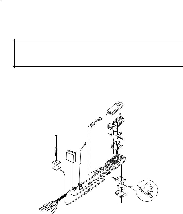
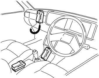
4.2.2 Wiring
Locations for the handsfree unit will vary according to the type of vehicle, as will the routing of power and interconnecting cables. The following precautions should be observed:
DO NOT install or connect the unit into a positive (+) grounded vehicle. This equipment must be installed into a 12V negative (-) ground vehicle.
Mount cables to the vehicle so that they are not prone to displacement or disconnection through vibration. Route cables through existing holes in the dashboard, bulkheads etc. where possible.
Site cables so that contact with moving parts (brake/clutch pedals, seat mechanisms etc.) is avoided. Site cables as far away as possible from existing cabling, to avoid electrical induction.
Shield cables to protect interference with the vehicle electronics.
When connecting cables to the vehicle circuitry, ensure that the vehicle functions are not affected.
A typical car installation is illustrated below, the actual location of units may vary according to vehicle type.:
Figure 3: Car installation |
500-0403 |
Wiring guide
Colour |
Connection |
Fuse |
|
|
|
|
|
Black |
Ground |
4A |
|
|
|
|
|
Blue |
Ignition |
3A |
|
|
|
|
|
Red |
Battery (+) |
3A |
|
|
|
|
|
Yellow |
Radio Mute |
— |
|
|
|
|
|
White |
Logic power |
— |
|
Black |
Battery (+) |
||
|
|||
|
|
|
NOTE:
The black and white paired wires are designed for use with an antenna compensator. Panasonic do not manufacture an antenna compensator and do not recommend the use of any third party antenna compensator.
MCUK960901C8 |
Section 4 |
Issue 1 |
Service Manual |
4 - 3 |
Revision 0 |

INSTALLATION GUIDE
4.2.3 Installation with the Adjustable Angle Bracket
The Adjustable Angle Bracket can be used to install the Handsfree Unit in the following configurations:

 HANDSFREE
ADJUSTABLE
 ANGLE BRACKET
SCREW
(XB4 + 10FN) Ø 4 mm 


 SCREW Ø 4 mm
SELF-TAPPING SCREW (XTB4 + 25RFN) Ø 4 mm
Ø 2 mm HOLE
30 mm
38 mm
30 mm
16 mm
38 mm
Ø 2 mm HOLE
 HANDSFREE
ADJUSTABLE 


 ANGLE BRACKET
SCREW


 (XB4 + 10FN) Ø 4 mm
SELF-TAPPING SCREW (XTB4 + 25RFN) Ø 4 mm
Figure 4: Adjustable angle bracket configurations |
500-0404 |
Issue 1 |
Section 4 |
MCUK960901C8 |
Revision 0 |
4 - 4 |
Service Manual |
 Loading...