


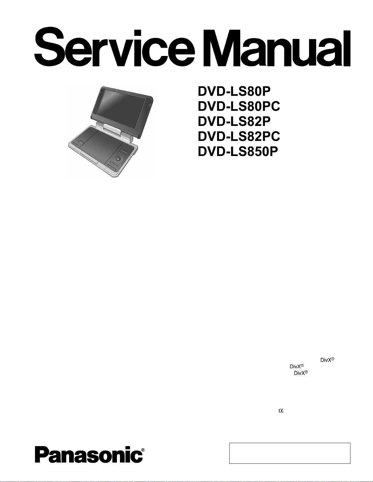
DVDLS-80-PC
)
r
s
ofv
S
l
s
:
LCDs
:
C
ORDER NO.CHM0703008CE
Portable DVD/CD PLAYER
RAE1909Z-C Mechanism Series
Colour
(S).................Silver Type (LS82)
(K).................Black Type (LS80/LS850)
B12
Specifications
Operating temperature
range: +5to +35°C (+41 to +95°F
Operating humidity range: 5-85% RH (no condensation)
Region number: Region No.1
Discs played
[8cm (3”) or 12cm (5”)]:
DVD [DVD-Video, DivX(*6,8)]
DVD-RAM [DVD-VR(*9),
JPEG(*4,6,7), MP3(*2,6),
MPEG4(*5,6), DivX(*6.8)]
DVD-R [DVD-Video,DVD-VR(*9),
JPEG(*4,6,7), MP3(*2,6),
MPEG4(*5,6), DivX(*6.8)]
DVD-R DL [DVD-Video,DVD-VR(*9)]
DVD-RW [DVD-Video,DVD-
VR(*9),JPEG(*4,6,7), MP3(*2,6),
MPEG4(*5,6), DivX(*6.8)]
+R/RW (Video)
+R DL (Video)
CD, CD-R/RW [CD-DA, Video-CD,
SVCD(*1), MP3(*2, 6), WMA(*3, 6),
JPEG (*4,6,7), MPEG4(*5,6),
DivX(*6.8),HighMAT Level 2 (Audio
and Image)]
*1:Conforming to IEC62107
*2:MPEG-1 Layer3,MPEG-2Layer3
*3:Windows Media Audio Ver9.0L3.
Not compatible with Multiple Bit Rate
(MBR)
igna
ystem
creen
omposite-videooutput/
input:
*4: Exif Ver 2.1JPEGBaselinefiles
Picture resolution: between 160×120
and 6144×4096 pixels (sub sampling
is 4:0:0, 4:2:0, 4:2:2 or 4:4:4)
*5: MPEG4 datarecorded withthe
Panasonic SD multi cameras or DVD
recorders.
Conforming toSDVIDEO
specifications (ASF standard)/MPEG4
(Simple Profile) video system/G.726
audio system.
*6: The total combinedmaximum
number of recognizable audio, picture
and movie contents and groups:
4000 audio, picture and movie
contents and 400 groups.
*7: Extremely longandslende
pictures may not be displayed.
*8: Plays all version
(including
playback of
Certified to the DivX Home Theater
Profile.
*9: CPRM doesn’tcope withit.
NTSC
8.5” -Si, TFT wide-screenLCD
6) with standard
media files.
ideo
© 2007 Matsushita Electric Industrial Co., Ltd. All
rights reserved. Unauthorized copying and
distribution is a violation of law.
)
DCo
1
CarDCa
DCo
1
B
y
p
m
i
D
V
7
C
2
D
V
7
C
4
D
2
x
4
D
:
[
D
[
]
M
D
:
a
D
a
M
8
s
:
T
N
S
s
ares
t
toc
.
DVD-LS80P / DVD-LS80PC / DVD-LS82P / DVD-LS82PC / DVD-LS850P
Output/input level: 1Vp-p (75W)
Output/input terminal: 3.5mm (1/8”) mini-jack
Number of terminals: 1system(output/input selectable)
Audio output/input:
Output/input level: 1.5Vrms(1kHz, 0dB, 10kW
Output/input terminal: 3.5mm (1/8”) stereo mini-jack
Number of terminals: 1system(output/input selectable)
Audio performance:
(1) Frequency response:
lDVD (linear audio): 4Hz-22kHz (48kHz sampling)
4Hz-44kHz (96kHz sampling)
lCD audio: 4Hz-20kHz
(2) S/N ratio:
lCD audio: 115dB
(3) Dynamic range:
lDVD (linear audio): 91dB
lCD audio: 92dB
(4) Total harmonic distortion:
lCD audio: 0.01%
Headphone output:
Output: 3.5mm (1/8”) stereo mini-jack
Number of terminals: 2systems
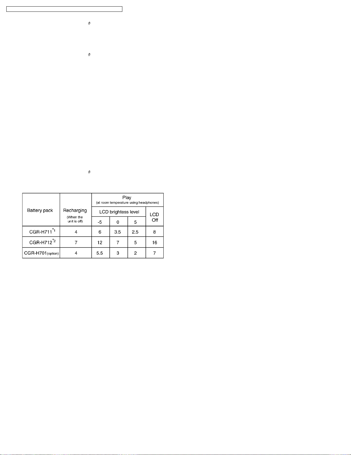
Battery duration (Hours):
utput:
2V, 1.3A
daptor:
utput:
2V 1.5A (Vehicle with12Vbattery
only)
atter
ack(lithiu
on):
VD-LS80,DVD-LS850
CGR-H711 (included):
oltage:
apacity:
.2V
250 mAh
VD-LS82
CGR-H712 (included):
oltage:
apacity:
imensions(excluding
protrusions and battery):
.2V
500 mAh
42.6(W) x 173.5(D)
9
[9
*23.9mm (
VD-LS80,DVD-LS850
D=173.5mm (627/32”)including
battery]
[H=46.6mm (1
VD-LS82:
D=179.3mm (71/16”)includingbattery
[H=51.5mm (21/32”) including battery]
ass(includingbattery):
VD-LS80,DVD-LS850
VD-LS82:
ass(withoutbattery):
pproximately 1032g(36.40oz)
pproximately 1120g(39.51oz)
90g (31.39 oz)
older
hismodelusesleadfreesolder (PbF).
ote
pecification
ubjec
hange without notice
Mass and dimensions are approximate.
6.0*(H)mm
/16”(W)x627/32”(D)x113/16”(H)]
15
/16”) at lowest point
27
/32”) including battery]
*1 included with DVD-LS80, DVD-LS850 (not available asoption).
*2 included with DVD-LS82.
lThe time indicated above may differdepending on use.
Pickup:
Wave length: 662nm/ 785nm (DVD/CD)
Laser power:
(For U.S.A.) CLASS II/ CLASS I (DVD/CD)
(For Canada) CLASS 1M/ CLASS 1M (DVD/CD)
Power supply: DC 12V (DC IN terminal) /
DC 7.2V (Exclusive battery terminal)
Power consumption
14W (Unit only: 12W)
(Using included AC adaptor):
Power consumption in
0.4W
Standby mode
(Using included AC adaptor):
Power consumption in
12W
Recharge mode
(Using included AC adaptor):
AC adaptor:
Power source: AC 100-240V, 50/60Hz
Power consumption: 22W
2
DVD-LS80P / DVD-LS80PC / DVD-LS82P / DVD-LS82PC / DVD-LS850P
CONTENTS
Page Page
1 SAFETY PRECAUTIONS 5
1.1. GENERAL GUIDELINES
2 PREVENTION OF ELECTRO STATIC DISCHARGE (ESD) TO
ELECTROSTATICALLY SENSITIVE (ES) DEVICES
3 PRECAUTION OF LASER DIODE
4 HOW TO REPLACE THE LITHIUM BATTERY
5 LITHIUM ION BATTERY
6 Service caution based on legal restrictions
6.1. General description about Lead Free Solder (PbF)
7 HANDLING PRECAUTIONS FOR TRAVERSE DECK
7.1. Handling of optical pickup
5
5
6
7
7
8
8
9
9
7.2. Grounding for electrostatic breakdown prevention
8 DISASSEMBLY, REASSEMBLY AND SERVICE POSITION
8.1. Disassembly
8.2. P.C.B. location
8.3. Main cabinet of the unit
8.4. Traverse assembly
8.5. Optical pick-up unit
8.6. Disc motor
8.7. Main P.C.B.
8.8. Operation P.C.B.
8.9. Monitor assembly
3
10
11
12
12
13
14
14
15
15
15
9

DVD-LS80P / DVD-LS80PC / DVD-LS82P / DVD-LS82PC / DVD-LS850P
8.10. Disc cover 16
8.11. Monitor cover
8.12. Mono arm
8.13. Inverter P.C.B.
8.14. LCD panel
8.15. Replacing the fuse in the car dc adaptor
8.16. Service position
9 SELF-DIAGNOSIS FUNCTION AND SERVICE MODE
9.1. Optical Pickup Breakdown Diagnosis
9.2. UHF displays
9.3. Service Mode Table 1
9.4. DVD Self Diagnostic Function-Error Code
9.5. Last Error Code saved during NO PLAY
9.6. Service mode table
9.7. Lens cleaning
10 SERV ICE PREC AUTIONS
10.1. Recovery after the dvd player is repaired
10.2. Firmware version-up of the DVD player
11 ADJUSTMENT PROC EDURES
11.1. Service Tools and Equipment
11.2. Important points in adjustment
11.3. Storing and Handling Test Discs
11.4. Optical adjustment
11.5. Electrical adjustment (LCD)
11.6. Electrical check (Video output check)
12 Abbreviations
13 VOL TAGE CHART
13.1. MAIN P.C.B.
14 BLOCK DIAGRAM
14.1. OVERALL BLOCK DIAGRAM
14.2. POWER SUPPLY BLOCK DIAGRAM
14.3. SERVO BLOCK DIAGRAM
14.4. AUDIO BLOCK DIAGRAM
14.5. VIDEO BLOCK DIAGRAM
15 INTERCONN ECTION SCHE MATIC DIAGRAM & SCHEMATIC
16
17
18
18
18
19
20
20
21
22
22
23
24
24
25
25
25
26
26
26
26
26
29
30
31
33
33
37
37
38
39
40
41
DIAGRAM NOTES
15.1. INTERCONNECTION SCHEMATIC DIAGRAM
15.2. SCHEMATIC DIAGRAM NOTES
16 SCHE MATIC DIAGRAM
16.1. CHARGE BATTERY SECTION (MAIN P.C.B. (1/9))
SCHEMATIC DIAGRAM
16.2. POWER SUPPLY SECTION (MAIN P.C.B. (2/9))
SCHEMATIC DIAGRAM
16.3. OPTICAL PICK UP/SERVO SECTION (MAIN P.C.B. (3/9))
SCHEMATIC DIAGRAM
16.4. DV5 SECTION (MAIN P.C.B. (4/9)) SCHEMATIC
DIAGRAM
16.5. VIDEO OUT SECTION (MAIN P.C.B. (5/9)) SCHEMATIC
DIAGRAM
16.6. AUDIO OUT SECTION (MAIN P.C.B. (6/9)) SCHEMATIC
DIAGRAM
16.7. OPERATION SECTION (MAIN P.C.B. (7/9)) SCHEMATIC
DIAGRAM
16.8. LCD IF SECTION (MAIN P.C.B. (8/9)) SCHEMATIC
DIAGRAM
16.9. CN SECTION (MAIN P.C.B. (9/9)) SCHEMATIC
DIAGRAM
16.10. OPERATION SECTION (OPERATION P.C.B.)
SCHEMATIC DIAGRAM
17 CIRCU IT BOARD ASSEMBLY
17.1. MAIN P.C.B. (1/2) (COMPONENT SIDE)
17.2. MAIN P.C.B. (2/2) (FOIL SIDE)
17.3. OPERATION P.C.B.
18 EXPLO DED VIEWS
18.1. Casing Parts & Mechanism Section Exploded View
18.2. Mechanism Section Exploded View
18.3. Packing & Accessories Exploded View
19 REPL ACEMENT PARTS LIST
20 Schematic Diagra m for printing with A4
43
43
44
45
45
46
47
48
49
50
51
52
53
54
55
55
56
57
59
59
60
61
63
71
4
DVD-LS80P / DVD-LS80PC / DVD-LS82P / DVD-LS82PC / DVD-LS850P
1 SAFETY PRECAUTIONS
1.1. GENERAL GUIDELINES
1. When servicing, observe the original lead dress. If a short circuit is found, replace all parts which have been overheated or
damaged by the short circuit.
2. After servicing, see to it that all the protective devices such as insulation barriers, insulation papers shields are properly
installed.
3. After servicing, make the following leakage current checks to prevent the customer from being exposed to shock hazards.
1.1.1. LEAKAGE CURRENT COLD
CHECK
1. Unplug the AC cord and connect a jumper between the two
prongs on the plug.
2. Measure the resistance value, with an ohmmeter, between
the jumpered AC plug and each exposed metallic cabinet
part on the equipment such as screwheads, connectors,
control shafts, etc. When the exposed metallic part has a
return path to the chassis, the reading should be between
1MW and 5.2MW.
When the exposed metal does not have a return path to
the chassis, the reading must be
.
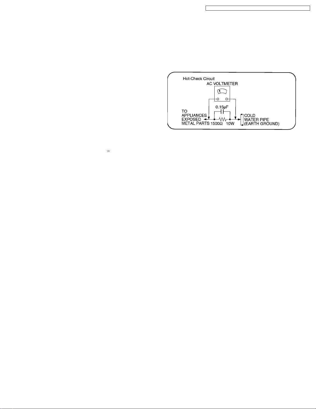
1.1.2. LEAKAGE CURRENT HOT CHECK
1. Plug the AC cord directly into the AC outlet. Do not use an
isolation transformer for this check.
2. Connect a 1.5kW, 10 watts resistor, in parallel with a 0.15µF
capacitors, between each exposed metallic part on the set
and a good earth ground such as a water pipe.
3. Use an AC voltmeter, with 1000 ohms/volt or more
sensitivity, to measure the potential across the resistor.
4. Check each exposed metallic part, and measure the
voltage at each point.
5. Reverse the ACplug in the AC outlet and repeat each of the
above measurements.
6. The potential at any point should not exceed 0.75 volts
RMS. A leakage current tester (Simpson Model 229 or
equivalent) may be used to make the hot checks, leakage
current must not exceed 1/2 milliamp. In case a
measurement is outside of the limits specified, there is a
possibility of a shock hazard, and the equipment should be
repaired and rechecked before it is returned to the
customer.
2 PREVENTION OF ELECTRO STATIC DISCHARGE (ESD)
TO ELECTROSTATICALLY SENSITIVE (ES) DEVICES
Some semiconductor (solid state) devices can be damaged easily by static electricity. Such components commonly are called
Electrostatically Sensitive (ES) Devices. Examples of typical ES devices are integrated circuits and some field-effect transistors and
semiconductor "chip" components. The following techniques should be used to help reduce the incidence of component damage
caused by electro static discharge (ESD).
1. Immediately before handling any semiconductor component or semiconductor-equipped assembly, drain off any ESD on your
body by touching a known earth ground. Alternatively, obtain and wear a commercially available discharging ESD wrist strap,
which should be removed for potential shock reasons prior to applying power to the unit under test.
2. After removing an electrical assembly equipped with ES devices, place the assembly on a conductive surface such as alminum
foil, to prevent electrostatic charge buildup or exposure of the assembly.
3. Use only a grounded-tip soldering iron to solder or unsolder ES devices.
4. Use only an anti-static solder removal device. Some solder removal devices not classified as "anti-static (ESD protected)" can
generate electrical charge sufficient to damage ES devices.
5. Do not use freon-propelled chemicals. These can generate electrical charges sufficient to damage ES devices.
6. Do not remove a replacement ES device from its protective package until immediately before you are ready to install it. (Most
replacement ES devices are packaged with leads electrically shorted together by conductive foam, alminum foil or comparable
conductive material).
7. Immediately before removing the protective material from the leads of a replacement ES device, touch the protective material
to the chassis or circuit assembly into which the device will be installed.
Caution
Be sure no power is applied to the chassis or circuit, and observe all other safety precautions.
5
DVD-LS80P / DVD-LS80PC / DVD-LS82P / DVD-LS82PC / DVD-LS850P
8. Minimize bodily motions when handling unpackaged replacement ES devices. (Otherwise hamless motion such as the brushing
together of your clothes fabric or the lifting of your foot from a carpeted floor can generate static electricity (ESD) sufficient to
damage an ES device).
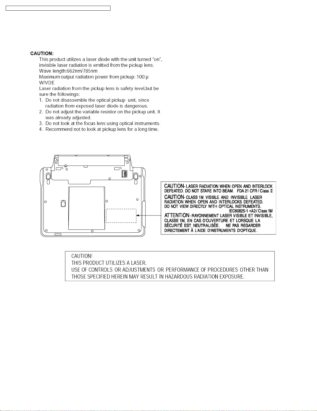
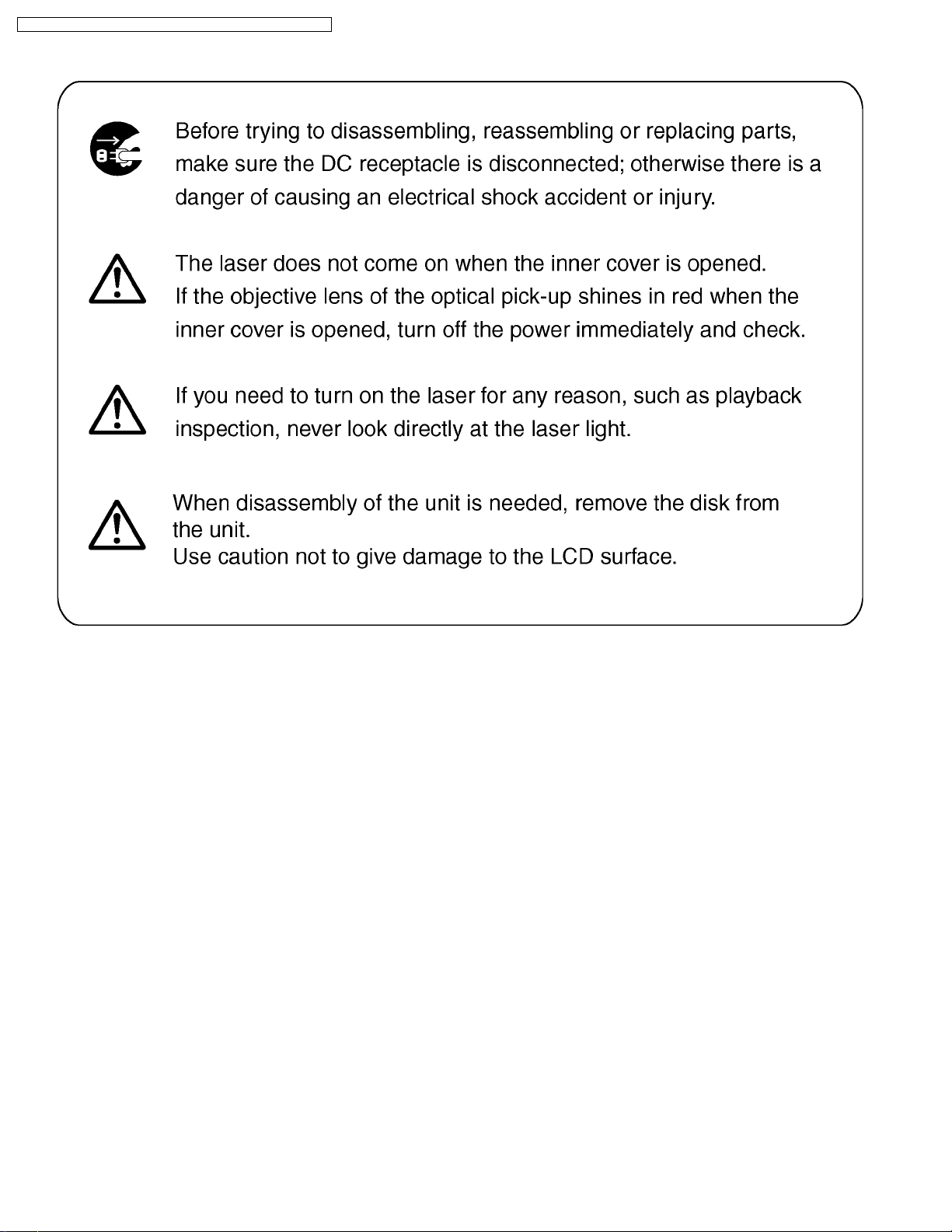
3 PRECAUTION OF LASER DIODE
6
DVD-LS80P / DVD-LS80PC / DVD-LS82P / DVD-LS82PC / DVD-LS850P
4 HOW TO REPLACE THE LITHIUM BATTERY
This model is using a lithium battery for the remote control ass’y.
NOTE:
The lithium battery is a critical component. ( Type No.: CR2025 Manufactured by Panasonic. )
It must never be subjected to excessive heat or discharge.
It must therefore only be fitted in equipment designed specifically for its use.
Replacement batteries must be of the same type and manufacture.
They must be fitted in the same manner and location as the original battery, with the correct polarity contacts observed.
Do not attempt to re-charge the old battery or re-use it for any other purpose.
It should be disposed of in waste products destined for burial rather than incineration.
5 LITHIUM ION BATTERY
7
DVD-LS80P / DVD-LS80PC / DVD-LS82P / DVD-LS82PC / DVD-LS850P
6 Service caution based on legal restrictions
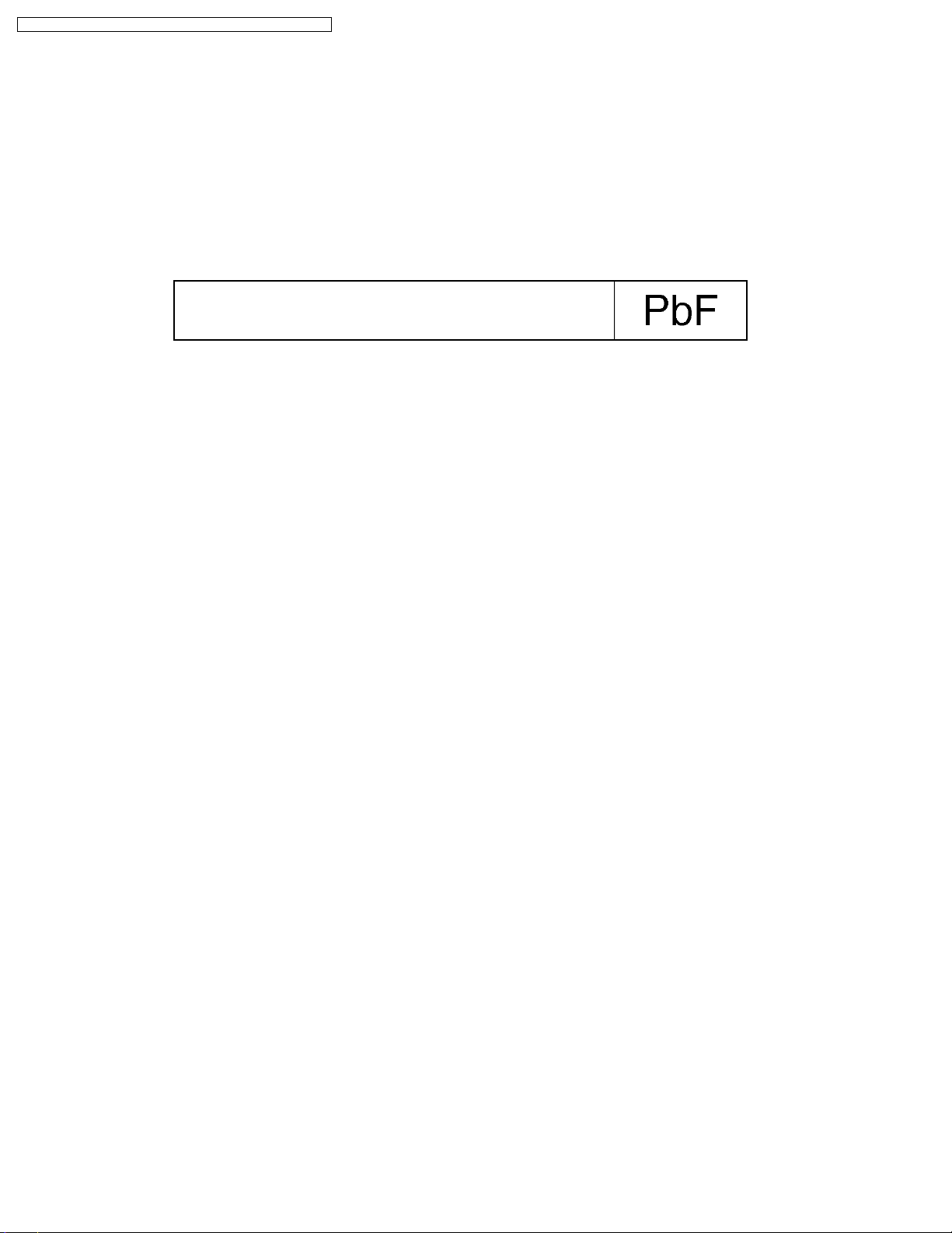
6.1. General description about Lead Free Solder (PbF)
The lead free solder has been used in the mounting process of all electrical components on the printed circuit boards used for this
equipment in considering the globally environmental conservation.
The normal solder is the alloy of tin (Sn) and lead (Pb). On the other hand, the lead free solder is the alloy mainly consists of tin
(Sn), silver (Ag) and Copper (Cu), and the melting point of the lead free solder is higher approx.30 degrees C (86 F) more than that
of the normal solder.
Definition of PCB Lead Free Solder being used
The letter of “PbF” is printed either foil side or components side on the PCB
using the lead free solder. (See right figure)
Service caution for repair work using Lead Free Solder (PbF)
- The lead free solder has to be used when repairing the equipment for which the lead free solder is used.(Definition: The letter
of "PbF" is printed on the PCB using the lead free solder.)
- To put lead free solder, it should be well molten and mixed with the original lead free solder.
- Remove the remaining lead free solder on the PCB cleanly for soldering of the new IC.
- Since the melting point of the lead free solder is higher than that of the normal lead solder, it takes the longer time to melt the
lead free solder.
- Use the soldering iron (more than 70W) equipped with the temperature control after setting the temperature at 350+-30
degrees C (662+-86 F).
Recommended Lead Free Solder (Service Parts Route.)
- The following 3 types of lead free solder are available through the service parts route.
RFKZ03D01K-----------(0.3mm 100g Reel)
RFKZ06D01K-----------(0.6mm 100g Reel)
RFKZ10D01K-----------(1.0mm 100g Reel)
Note
* Ingredient: tin (Sn) 96.5%, silver (Ag) 3.0%, Copper (Cu) 0.5%, Cobalt (Co) / Germanium (Ge) 0.1 to 0.3%
8
DVD-LS80P / DVD-LS80PC / DVD-LS82P / DVD-LS82PC / DVD-LS850P
7 HANDLING PRECAUTIONS FOR TRAVERSE DECK
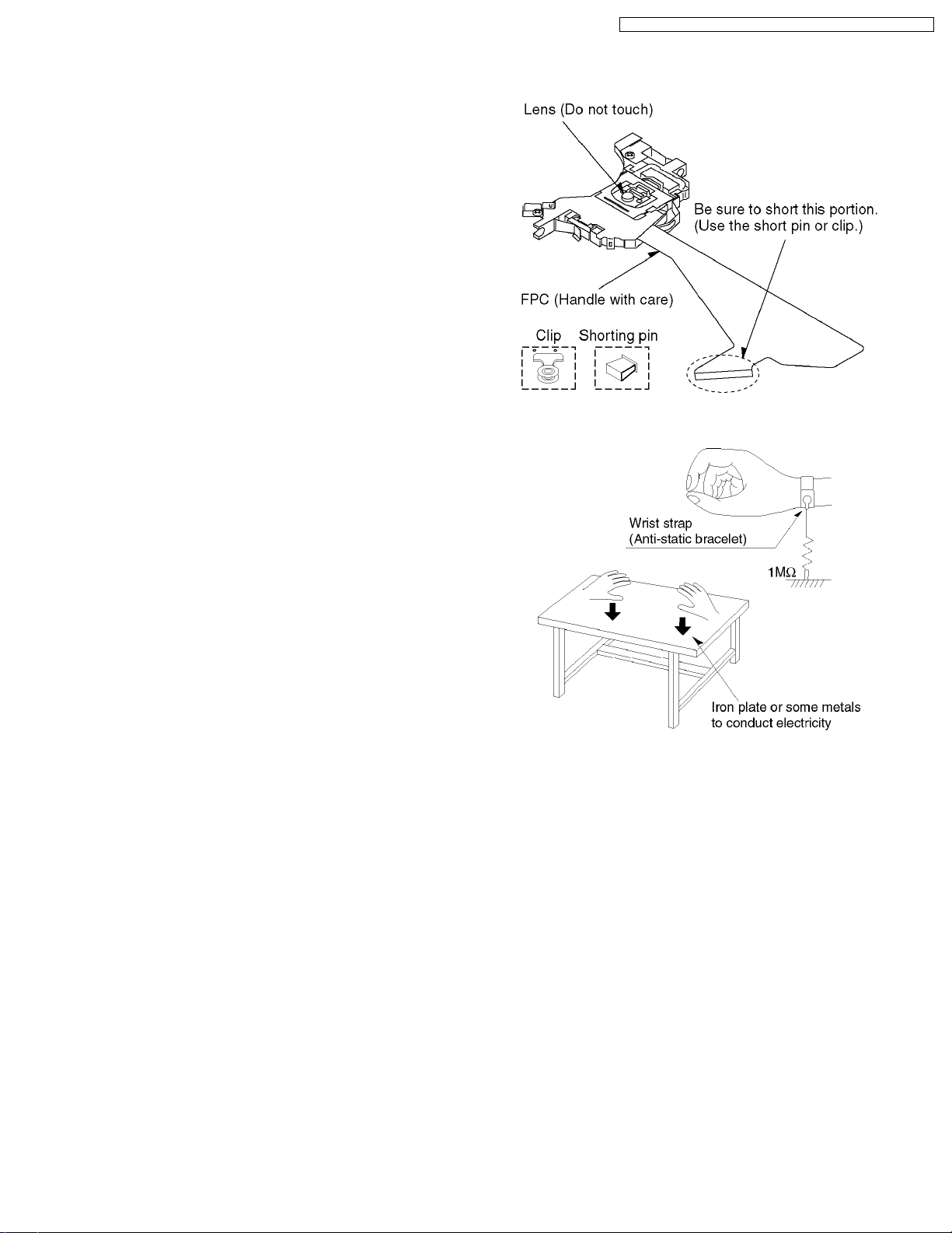
The laser diode in the optical pickup may break down due to
potential difference caused by static electricity of clothes or
human body.
So be careful of electrostatic break down during repair of the
optical pickup.
It has already been adjusted.
7.1. Handling of optical pickup
1. Do not subject the optical pickup to static electricity as it is
extremely sensitive to electrical shock.
2. To prevent the breakdown of the laser diode, an antistatic
shorting pin is inserted into the flexible board (FPC Board).
When removing or connecting the short pin, finish the job in
as short times as possible.
3. Be careful not to apply excessivestress to theflexible board
(FPC Board).
4. Do not turn the variable resistor (Laser power adjustment).
7.2. Grounding for electrostatic breakdown prevention
1. Human body grounding
Use the antistatic wrist strap to discharge the static
electricity from your body.
2. Work table grounding
Put a conductive material (sheet) or steel sheet on the area
where the optical pickup is placed and ground the sheet.
Caution
The static electricity of your clothes will not be grounded
through the wrist strap. So take care not to let your
clothes touch the optical pickup.
9
DVD-LS80P / DVD-LS80PC / DVD-LS82P / DVD-LS82PC / DVD-LS850P
8 DISASSEMBLY, REASSEMBLY AND SERVICE POSITION
10

8.1. Disassembly
DVD-LS80P / DVD-LS80PC / DVD-LS82P / DVD-LS82PC / DVD-LS850P
11
DVD-LS80P / DVD-LS80PC / DVD-LS82P / DVD-LS82PC / DVD-LS850P
8.2. P.C.B. location
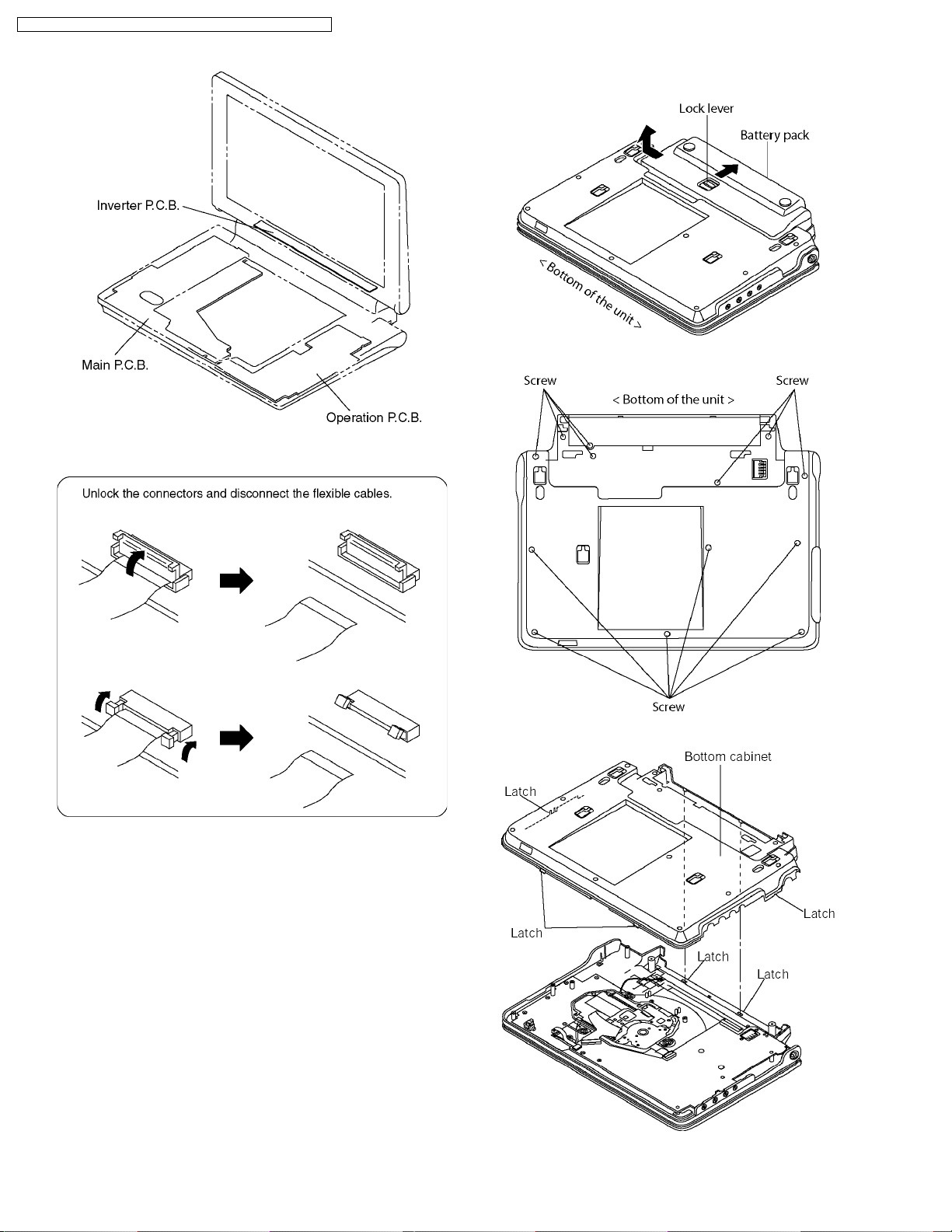
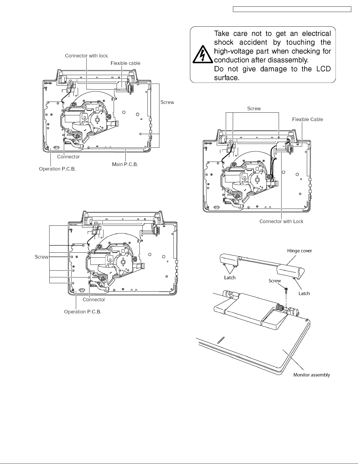
8.3. Main cabinet of the unit
<Removing battery pack>
Release the lock lever and remove the battery pack in the
direction of the arrow.
1. Remove the 13 screws from the bottom of the unit.
2. Release the latches and remove the bottom cabinet.
12
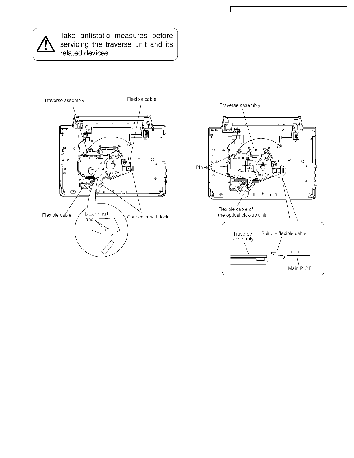
8.4. Traverse assembly
8.4.1. Removing traverse assembly
1. Solder the 2 laser short lands on the flexible cable.
2. Unlock the connectors and remove the flexible cables.
DVD-LS80P / DVD-LS80PC / DVD-LS82P / DVD-LS82PC / DVD-LS850P
8.4.2. Reinstalling traverse assembly
1. Reinstall the traverse assembly to the specified pin of the
unit.
2. Reinstall the flexible cable of the optical pickpup unit and
lock it securely.
3. Remove the solder of each laser short land of the flexible
cable.
Caution:
Remove the solders completely: otherwise the laser
diode won’t emit light.
4. Reinstall the spindle flexible cable as shown figure.
13
DVD-LS80P / DVD-LS80PC / DVD-LS82P / DVD-LS82PC / DVD-LS850P
8.5. Optical pick-up unit
8.5.1. Removing optical pick-up unit
8.5.2. Reinstalling optical pick-up unit
The optical pick-up unit is factory adjusted. Do not touch the
adjustment screw.
1. Reassemble the disassembled parts in the reverse order of
disassembly.
2. When reinstalling the traverse assembly on the main unit
after installing the optical pick-up unit, make sure to remove
the solder from each of the two laser short lands on the
flexible cable.
Caution:
·
· Remove the solders completely; otherwise the laser
· ·
diode won´t emit light.
·
· After replacing the optical pick-up unit, check the quality
· ·
of images played back and make optical adjustment.
8.6. Disc motor
8.6.1. Removing disc motor
1. Remove the adjustment screws A, B, and C.
2. Remove the disc motor.
Make sure that the traverse assembly removed before trying to
remove the optical pick-up unit.
When removing the traverse assembly, solder the two laser
short lands on the flexible cable of the optical pick-up unit.
1. Remove the two screws securing the main shaft retainer.
2. Remove the main shaft retainer.
3. Slide the main shaft in the direction indicated by the arrow
to remove the optical pick-up unit.
8.6.2. Caution to be taken when
replacing the disc motor
1. The mounting screws of the disc motor also serve as
adjustment screws. When reinstalling the disc motor, first
turn the screws A, B, and C as far as they go by usual force
to secure them (do not overtighten).
2. Back off the adjustment screws Aand C two complete turns
and secure them.
3. Back off the adjustment screw B one and a half turns and
secure them.
·
· This makes it nearly possible to play back disks and
· ·
adjust the jitter.
Thereafter, adjust the adjustment screws C and A as
indicated.
14
8.7. Main P.C.B.
1. Unlock the connector and remove the flexible cable.
2. Remove the connector.
3. Remove the 3 screws and remove the main P.C.B..
DVD-LS80P / DVD-LS80PC / DVD-LS82P / DVD-LS82PC / DVD-LS850P
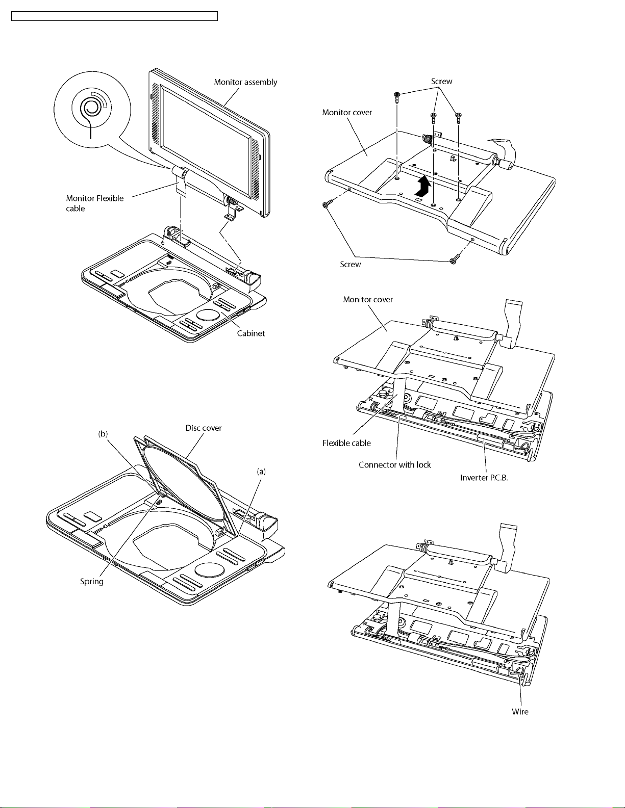
8.9. Monitor assembly
1. Unlock the connector and remove the flexible cable.
2. Remove the 3 screws.
8.8. Operation P.C.B.
1. Remove the connector.
2. Remove the 7 screws and remove the operation P.C.B.
3. Release the latches and remove the hinge cover.
4. Remove the screw and remove the monitor assembly.
15
DVD-LS80P / DVD-LS80PC / DVD-LS82P / DVD-LS82PC / DVD-LS850P
<Caution to be taken when installing monitor assembly>
1. Roll the flexible cable as shown figure.
2. Install the monitor assembly on the cabinet.
8.11. Monitor cover
1. Remove the 5 screws
2. Remove the monitor cover into the direction of the arrow.
3. Unlock the connector and remove the flexible cable.
8.10. Disc cover
1. Remove the disc cover in order of (a) and (b).
Caution:
Please don’t lose the spring
<Caution to be taken when installing monitor cover>
Please do not nip the wire.
16
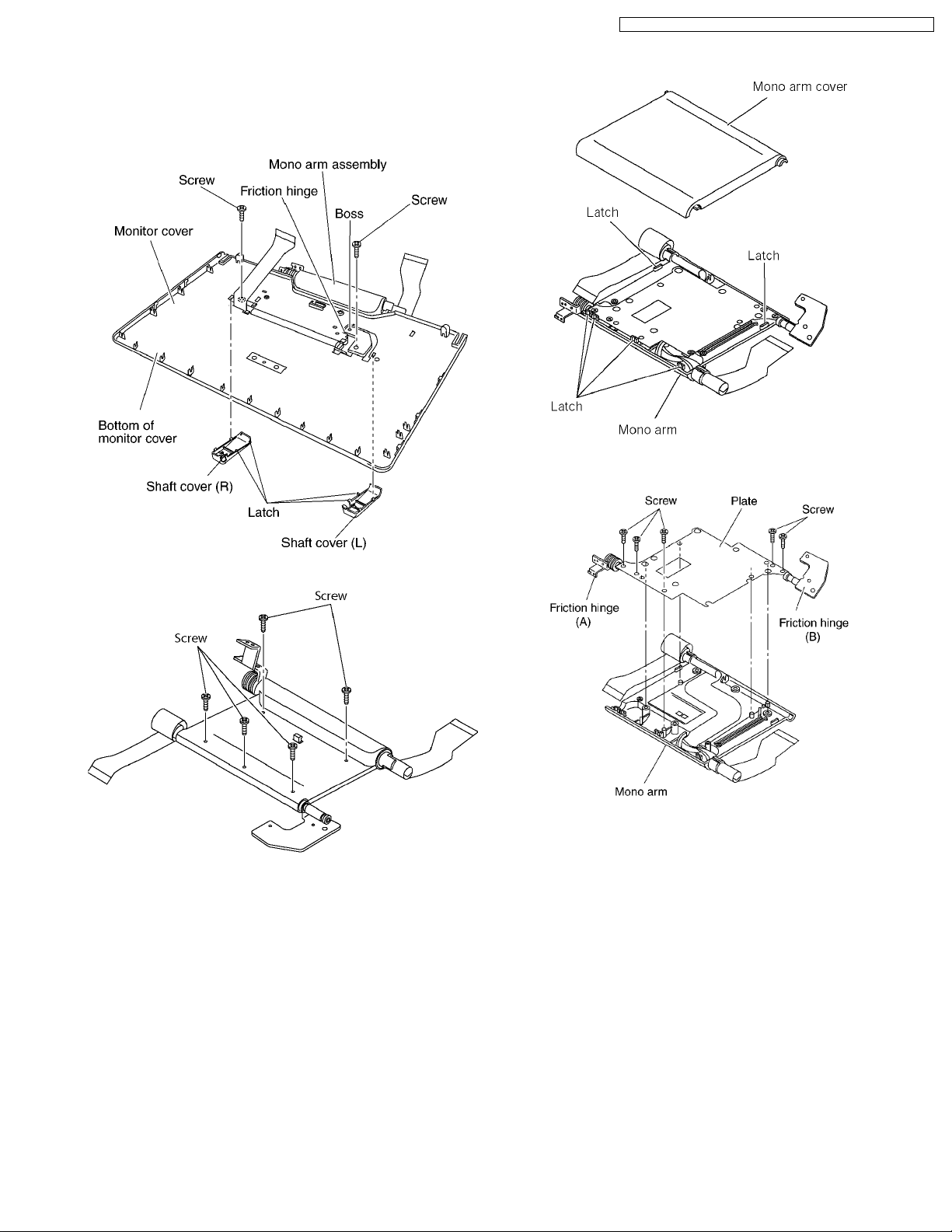
8.12. Mono arm
1. Remove the 2 screws.
2. Release the latches and remove the shaft covers.
3. Release the friction hinge from boss and remove the mono
arm assembly.
DVD-LS80P / DVD-LS80PC / DVD-LS82P / DVD-LS82PC / DVD-LS850P
5. Release the latches and remove the mono arm cover
6. Remove the plate and friction hinge (A)/(B).
4. Remove the 5 screws.
17

DVD-LS80P / DVD-LS80PC / DVD-LS82P / DVD-LS82PC / DVD-LS850P
<Caution to be taken when installing mono arm>
1. Roll the flexible cables as shown figure and install it to
mono arm c over.
2. Install mono arm.
3. Roll 3 turns of the flexible cable and Install the shaft
cover (R) to flexible cable.
4. Pass the flexible cable and the friction hinge into the
holes in the monitor cover.
5. Install the shaft covers to monitor cover.
8.13. Inverter P.C.B.
1. Unlock the connector and remove the flexible cable.
2. Remove the 4 screws.
3. Remove the monitor support angle.
4. Remove the connector and remove the inverter P.C.B. and
2 speaker.
8.14. LCD panel
1. Remove the LCD panel into the direction of the arrow.
8.15. Replacing the fuse in the car
dc adaptor
·
· Replace only with the specified 125V/250V, 3A fuse. Use of
· ·
any other type can cause fire.
18

DVD-LS80P / DVD-LS80PC / DVD-LS82P / DVD-LS82PC / DVD-LS850P
8.16. Service position
8.16.1. Board checks
1. Connect the main P.C.B and the traverse assembly with an extension cable.
2. Install the traverse assembly to the tilt adjustment jig using three screws and three washers.
Caution:
·
· Remove the rubber cushion from the traverse assembly to prevent it from getting damaged.
· ·
3. Install a dick on the traverse assembly.
Caution:
·
· Make sure the disk is securely installed on the disk motor.
· ·
4. Remove the main P.C.B., operation P.C.B., inverter P.C.B., and LCD panel as shown below.
5. The disk cannot be played back with the disk cover removed.
19
DVD-LS80P / DVD-LS80PC / DVD-LS82P / DVD-LS82PC / DVD-LS850P
9 SELF-DIAGNOSIS FUNCTION AND SERVICE MODE
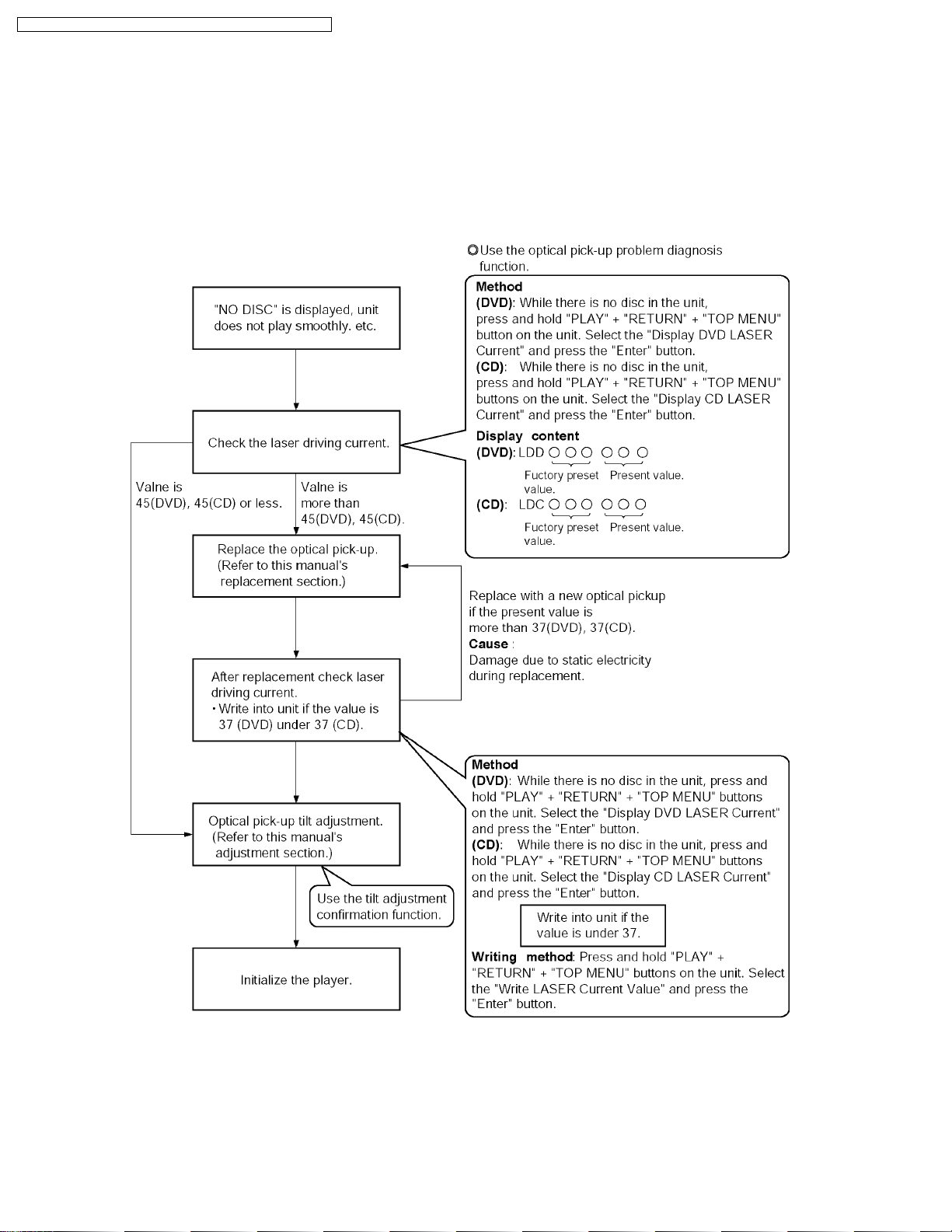
9.1. Optical Pickup Breakdown Diagnosis
As a new feature, this unit has an “optical pick-up problem diagnosis function” and “a tilt adjustment confirmation function” built
in. Use the following procedure to efficiently determine the problem and adjust tilt.If "NO DISC" is displayed, before exchanging
the optical pick-up, carry out problem diagnosis first. If the present laser driving current is over 55, the optical pick-up may need
to be exchanged.
Note:
Carry out diagnosis within 3 minutes of turning the unit on. (T he player’s current can increase as it warms up, so turn the unit
off and allow it to cool down before diagnosis.)
20

Cautions to be taken when replacing the optical pickup
The optical pickup may break down due to the static
electricity of human body. Take proper protection measures
against static electricity before repairing the parts around
the optical pickup. (See the page describing the
PREVENTION OF STATIC ELECTRICITY DISCHARGE.)
1. Do not touch the areas around the laser diode and
actuator.
2. Do not judge the laser diode with a tester. (The tester
will be damaged easily.)
3. It is recommended to use a destaticized soldering iron
DVD-LS80P / DVD-LS80PC / DVD-LS82P / DVD-LS82PC / DVD-LS850P
for short-circuiting or removing the laser diode.
(Recommended soldering iron) HAKKO ESD Product
4. Solder the land of the flexible cable in the optical pickup.
Note:
·
· When using a soldering iron which is not
· ·
destaticized, short-circuit the terminal face of the
flexible case with a clip. After that, short-circuit
the land.
·
· After the repairing work is completed, remove the
· ·
solder according to the correct procedure shown
in this Technical Guide.
9.2. UHF displays
Use the internal service mode for evaluation of malfunctions.
Display Method Display Diagnosis
Items displayed when in use CHECK THE
Press the [PLAY] + [RETURN] + [TOP MENU] buttons
on the unit. Select the “Display ErrorCode” and press
the “Enter” button.
The last error code generated is saved in the EEPROM
DISC
H01 Inner cover trouble
H02 Spindle servo error
H03 Traverse error
H04 Tracking servo error
H05 Seek error
F0** Disc format error
F1** Disc code error
F2** Decoder LSI error
F5** DSC
F6** ECC error
F7** Microcomputer error
F8** Microcomputer error
Focus error
21
 Loading...