


 Loading...
NEC NP4100W-10ZL, NP4100W-09ZL, NP4100W-08ZL, NP4100W-06FL, NP4100W-07ZL User Manual
...Projector
NP4100/NP4100W
User’s Manual
Second edition, March 2009
•DLP, BrilliantColor and DynamicBlack are trademarks of Texas Instruments.
•IBM is a trademark or registered trademark of International Business Machines Corporation.
•Macintosh, Mac OS X and PowerBook are trademarks of Apple, Inc., registered in the U.S. and other countries.
•Windows, PowerPoint, Internet Explorer, Windows 98, Windows Me, Windows 2000, Windows XP or Windows Vista are trademarks or registered trademarks of Microsoft Corporation.
•VESA is a registered trademark of Video Electronics Standards Association.
•Trademark PJLink is a trademark applied for trademark rights in Japan, the United States of America and other countries and areas.
•Other product and company names mentioned in this user's manual may be the trademarks or registered trademarks of their respective holders.
Notes
(1)The contents of this user’s manual may not be reprinted in part or whole without permission.
(2)The contents of this user’s manual are subject to change without notice.
(3)Great care has been taken in the preparation of this user’s manual; however, should you notice any questionable points, errors or omissions, please contact us.
(4)Notwithstanding article (3), NEC will not be responsible for any claims on loss of profit or other matters deemed to result from using the Projector.
Important Information
Safety Cautions
Precautions
Please read this manual carefully before using your NEC NP4100/NP4100W projector and keep the manual handy for future reference. Your serial number is located on the bottom of your projector.
Record it here:
CAUTION:
To turn off main power, be sure to remove the plug from power outlet. The power outlet socket should be installed as near to the equipment as possible, and should be easily accessible.
CAUTION:
•TO PREVENT SHOCK, DO NOT OPEN THE CABINET.
• THERE ARE HIGH-VOLTAGE COMPONENTS INSIDE.
•REFER SERVICING TO QUALIFIED SERVICE PERSONNEL.
This symbol warns the user that un-insulated voltage within the unit may be sufficient to cause electrical shock. Therefore, it is dangerous to make any kind of contact with any part inside of the unit.
This symbol alerts the user that important information concerning the operation and maintenance of this unit has been provided.
The information should be read carefully to avoid problems.
WARNING:
To prevent fire or shock, do NOT expose this unit to rain or moisture. Do NOT use this unit’s plug with an extension cord or in an outlet unless all the prongs can be fully inserted.
DOC Compliance Notice (for Canada only)
This Class B digital apparatus meets all requirements of the Canadian InterferenceCausing Equipment Regulations.
Machine Noise Information Regulation - 3. GPSGV (for Germany only)
The highest sound pressure level is less than 70 dB (A) in accordance with EN ISO 7779.
i
Important Information
Laser Rating
This label is on the side of the remote control.
This mark is on the top of the remote control.
CAUTION |
Use of controls or adjustments or performance of procedures other than |
|
|
|
those specified herein may result in hazardous radiation exposure. |
CAUTION |
Do not look into the laser pointer while it is on and do not point the laser |
|
|
|
beam at a person. Serious injury could result. |
Disposing of your used product
EU-wide legislation as implemented in each Member State requires that used electrical and electronic products carrying the mark (left) must be disposed of separately from normal household waste. This includes projectors and their electrical accessories or lamps. When you dispose of such products, please follow the guidance of your local authority and/or ask the shop where you purchased the product. After collecting the used products, they are reused and recycled in a proper way. This effort will help us reduce the wastes as well as the negative impact such as mercury contained in a lamp to the human health and the environment at the minimum level. The mark on the electrical and electronic products only applies to the current European Union Member States.
WARNING TO CALIFORNIA RESIDENTS:
Handling the cables supplied with this product will expose you to lead, a chemical known to the State of California to cause birth defects or other reproductive harm. Wash hands after handling.
ii

Important Information
RF Interference (for USA only)
WARNING:
The Federal Communications Commission does not allow any modifications or changes to the unit EXCEPT those specified by NEC Display Solutions of America, Inc. in this manual. Failure to comply with this government regulation could void your right to operate this equipment. This equipment has been tested and found to comply with the limits for a Class B digital device, pursuant to Part 15 of the FCC Rules. These limits are designed to provide reasonable protection against harmful interference in a residential installation. This equipment generates, uses, and can radiate radio frequency energy and, if not installed and used in accordance with the instructions, may cause harmful interference to radio communications. However, there is no guarantee that interference will not occur in a particular installation.
If this equipment does cause harmful interference to radio or television reception, which can be determined by turning the equipment off and on, the user is encouraged to try to correct the interference by one or more of the following measures:
Reorient or relocate the receiving antenna.
Increase the separation between the equipment and receiver.
Connect the equipment into an outlet on a circuit different from that to which the receiver is connected.
Consult the dealer or an experienced radio / TV technician for help.
For UK only: In UK, a BS approved power cable with molded plug has a Black (five Amps) fuse installed for use with this equipment. If a power cable is not supplied with this equipment please contact your supplier.
Important Safeguards
These safety instructions are to ensure the long life of your projector and to prevent fire and shock. Please read them carefully and heed all warnings.
Installation
• Do not place the projector in the following conditions:
On an unstable cart, stand, or table.
Near water, baths or damp rooms.
In direct sunlight, near heaters or heat radiating appliances.
In a dusty, smoky or steamy environment.
On a sheet of paper or cloth, rugs or carpets.
iii
Important Information
• If you wish to have the projector installed on the ceiling:
Do not attempt to install the projector yourself.
The projector must be installed by qualified technicians in order to ensure proper operation and reduce the risk of bodily injury.
In addition, the ceiling must be strong enough to support the projector and the installation must be in accordance with any local building codes.
Please consult your dealer for more information.
CAUTION:
When shipping the projector, remove the optional lens beforehand. The lens and the lens shift mechanism may encounter damage caused by improper handling during transportation.
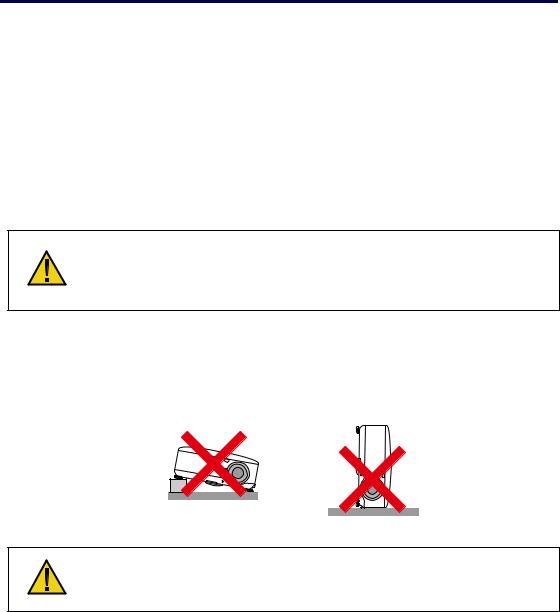
Place the projector in a horizontal position
Do not put the projector on its side when the lamp is turned on. Doing so may cause damage to the projector.
CAUTION:
Do not drop the projector on your hand or fingers while lifting the projector to replace the filters. Doing so could injure your hand or fingers.
iv
Important Information
Fire and Shock Precautions
•Ensure that there is sufficient ventilation and that vents are unobstructed to prevent the build-up of heat inside your projector (see page ix, x).
•Do not try to touch the ventilation outlet on the rear as it can become heated while the projector is turned on and immediately after the projector is turned off.
•Prevent foreign objects such as paper clips and bits of paper from falling
into your projector. Do not attempt to retrieve any objects that might fall into your projector. Do not insert any metal objects such as a wire or screwdriver into your project. If something should fall into your projector, disconnect it immediately and have the object removed by qualified service personnel.
•Do not place any objects on top of the projector.
•Do not touch the power plug during a thunderstorm. Doing so can cause electrical shock or fire.
•The projector is designed to operate on a power supply of 100-240V AC 50/60 Hz. Ensure that your power supply fits this requirement before attempting to use your projector.
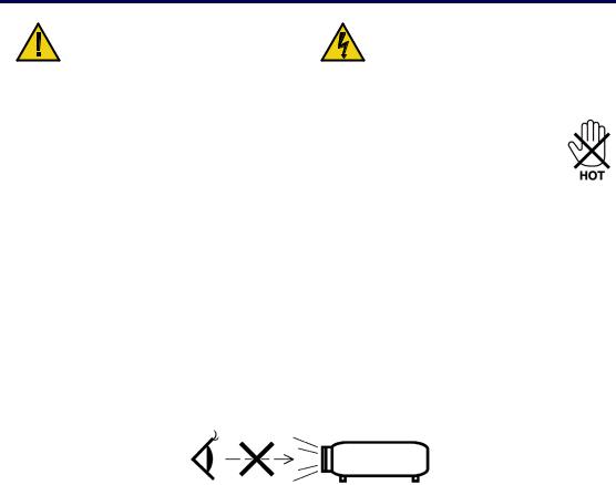
•Do not look into the lens while the projector is on. Serious damage to your eyes could result.
•Keep any items such as magnifying glass out of the light path of the projector. The light being projected from the lens is extensive, therefore any kind of abnormal objects that can redirect light coming out of the lens, can cause unpredictable outcome such as fire or injury to the eyes.
•Do not cover the lens with the black lens cap or equivalent while the projector is on. Doing so can lead to melting of the cap and possibly burning your hands due to the heat emitted from the light output.
•Do not place any objects, which are easily affected by heat, in front of the projector lens or a projector exhaust vent. Doing so could lead to the object melting or getting your hands burned from the heat that is emitted from the light output and exhaust.
•Handle the power cable carefully. A damaged or frayed power cable can cause electric shock or fire.
Do not use any power cables other than the one supplied by NEC. Do not bend or tug the power cable excessively.
Do not place the power cable under the projector, or any heavy object. Do not cover the power cable with other soft materials such as rugs. Do not heat the power cable
Do not handle the power plug with wet hands.
v

Important Information
•Turn off the projector, unplug the power cable and have the projector serviced by qualified service personnel under the following conditions:
When the power cable or plug is damaged or frayed.
If liquid has been spilled into the projector, or if it has been exposed to rain or water.
If the projector does not operate normally when you follow the instructions described in this user's manual.
If the projector has been dropped or the cabinet has been damaged.
If the projector exhibits a distinct change in performance, indicating a need for service.
•Disconnect the power cable and any other cables before carrying the projector.
•Turn off the projector and unplug the power cable if the projector is not to be used for an extended period of time.
•When using a LAN cable:
For safety, do not connect to the connector for peripheral device wiring that might have excessive voltage.
•Turn off the projector and unplug the power cable before cleaning the cabinet or replacing the lamp.
CAUTION:
•Always carry your projector by using the carrying handle.
•Do not use the tilt-foot for purposes other than originally intended. Misuses such as using the tilt foot to carry or hang (from the wall or ceiling) the projector can cause damage to the projector.
•Do not send the projector in the soft case by parcel delivery service or cargo shipment. The projector inside the soft case could be damaged.
•Do not unplug the power cable from the wall outlet or projector when the projector is powered on. Doing so can cause damage to the AC IN connector of the projector and (or) the prong plug of the power cable.
•To turn off the AC power supply when the projector is powered on, use a power strip equipped with a switch and a breaker.
•The projector can be unplugged during its cool down period after it is turned off.
•Do not try to touch the ventilation outlet on the rear as it can become heated while the projector is turned on and immediately after the projector is turned off.
•Do not turn off the AC power for 60 seconds after the lamp is turned on and while the POWER indicator is blinking green. Doing so could cause premature lamp failure.
•Do not place your hands near the lens opening while shifting the lens. Shifting the lens could pinch your fingers or hands causing injury.
vi

Important Information
Remote Control Precautions
•Handle the remote control carefully.
•If the remote control gets wet, wipe it dry immediately.
•Avoid excessive heat and humidity.
•Do not heat, take apart, or throw batteries into fire.
•If you will not be using the remote control for a long time, remove the batteries.
•Ensure that you have the batteries' polarity (+/–) aligned correctly.
•Do not use new and old batteries together, or use different types of batteries together.
•Dispose of used batteries according to your local regulations.
Lamp Replacement
To replace either of the lamps, follow all instructions provided on page 112. Be sure to replace the lamp when the following is displayed on the screen:
If you continue to use the lamp after the lamp has reached the end of its usable life, the lamp bulb may shatter, and pieces of glass may be scattered in the lamp case. Do not touch them as the pieces of glass may cause injury.
If this happens, contact your dealer for lamp replacement.
Important Lamp Characteristic
The projector has a high-pressure mercury lamp as a light source.
A characteristic of mercury lamps is that brightness gradually decreases with age. Also repeatedly turning the lamp on and off will increase the possibility of reduced brightness.
CAUTION:
When removing the lamp from a ceiling-mounted projector, make sure that no one is under the projector. Glass fragments could fall if the lamp has been burned out.
CAUTION:
In rare cases the lamp bulb may burn out during normal operation and cause glass dust or shards to be discharged outward from the rear exhaust vent.
Do not inhale or do not touch glass dust or shards. Doing so could result in injury.
vii
Important Information
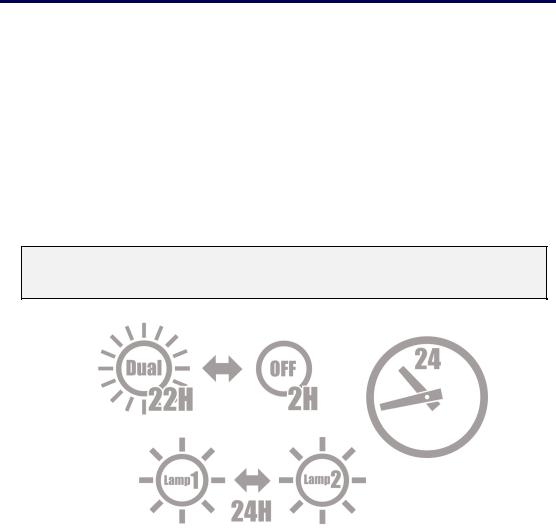
[Important 1] Operating the Lamp Continuously
If using the projector continuously for a long period, use of the menu (OSD) is recommended in order to properly cycle the lamps as described below.
To use the projector continuously in the dual lamp mode
Allow 2 hours per day of non usage time per lamp. Do this for both lamps at the same time or for “Lamp 1” and “Lamp 2” at separate 2 hour intervals.
To use the projector continuously in single lamp mode
Use the two lamps (Lamp 1 and Lamp 2) alternately in a cycle of 24 hours or less. Allow 2 hours or longer per day of no-use time for each lamp.
Contact your dealer for more details.
Note:
If using the menu, select "Off" for "Lamp Interval" from the on-screen menu (see page 82).
viii
Important Information
[Important 2] Clearance for Installing the Projector
Allow ample clearance between the projector and its surroundings as shown below. Avoid installing the projector in a place where air movement from the HVAC is directed at the projector.
Heated air from the HVAC can be taken in by the projector's intake vent. If this happens, the temperature inside the projector will rise too high causing the over-temperature protector to automatically turn off the projectors power.
Example 1 – If there are walls on both sides of the projector.
Note:
The drawing shows the proper clearance required for the front, back and top of the projector.
Example 2 – If there is a wall behind the projector.
(1) For floor installation:
Note:
The drawing shows the proper clearance required for the back, sides and top of the projector.
(2) For ceiling mounting:
Note:
1. The drawing shows the proper clearance required for the front, sides, back and bottom of the projector.
2. If suspending the projector 30 cm/12 inches away from the ceiling, allow ample clearance for all four sides and the under the projector.
ix

Important Information
(3) Upward or downward projection:
When using the projector in an upward projection angle, allow 1 m/ 40 inches or greater between the exhaust vent and the wall.
When using the projector in a downward projection angle, allow 0.5 m/ 20 inches or greater between the exhaust vent and the wall.
x

Table of Contents
IMPORTANT INFORMATION............................................................................................................. |
I |
SAFETY CAUTIONS................................................................................................................................ |
I |
1. INTRODUCTION .............................................................................................................................. |
1 |
WHAT’S IN THE BOX? ...................................................................................................................... |
1 |
INTRODUCTION TO THE PROJECTOR............................................................................................... |
2 |
Features you’ll enjoy:.................................................................................................................... |
2 |
PART NAMES OF THE PROJECTOR.................................................................................................. |
3 |
Front-right view.............................................................................................................................. |
3 |
Top View......................................................................................................................................... |
4 |
Carrying the Projector................................................................................................................... |
5 |
Bottom view.................................................................................................................................... |
6 |
TOP FEATURES................................................................................................................................ |
7 |
Lens Controls................................................................................................................................. |
7 |
OSD Controls and Status LEDS ................................................................................................. |
8 |
TERMINAL PANEL FEATURES ........................................................................................................ |
10 |
PART NAMES OF THE REMOTE CONTROL..................................................................................... |
12 |
Battery Installation....................................................................................................................... |
14 |
Operating Range for Wireless Remote Control ...................................................................... |
15 |
Remote Control Precautions ..................................................................................................... |
15 |
Using the Remote Control in Wired Operation ....................................................................... |
16 |
2. INSTALLATION AND CONNECTIONS...................................................................................... |
17 |
SETTING UP THE SCREEN AND THE PROJECTOR ......................................................................... |
17 |
SELECTING A LOCATION................................................................................................................ |
18 |
INSTALLING OR REMOVING THE OPTIONAL LENS ......................................................................... |
19 |
Removing the Existing Lens From the Projector .................................................................... |
19 |
Installing the New Lens .............................................................................................................. |
21 |
Installing the New Lens Using the anti-theft screw ................................................................ |
21 |
THROW DISTANCE AND SCREEN SIZE .......................................................................................... |
22 |
NP4100 Throw Distance and Screen Size Values................................................................. |
23 |
NP4100W Throw Distance and Screen Size Values ............................................................. |
24 |
REPLACING COLOR WHEEL .......................................................................................................... |
27 |
MAKING CONNECTIONS................................................................................................................. |
31 |
Connecting Your PC or Macintosh Computer......................................................................... |
31 |
Connecting an External Monitor................................................................................................ |
33 |
Connecting Your DVD Player with Component Output ......................................................... |
34 |
Connecting Your VCR ................................................................................................................ |
35 |
CONNECTING TO A NETWORK ....................................................................................................... |
36 |
CONNECTING THE SUPPLIED POWER CABLE ............................................................................... |
37 |
3. PROJECTING AN IMAGE (BASIC OPERATION) ................................................................... |
38 |
TURNING ON THE PROJECTOR ...................................................................................................... |
38 |
Note on Startup Screen (Menu Language Select screen) .................................................... |
39 |
SELECTING A SOURCE .................................................................................................................. |
40 |
ADJUSTING THE PICTURE POSITION AND PICTURE SIZE.............................................................. |
41 |
Adjusting Picture Position Manually ......................................................................................... |
41 |
xi |
|

|
Table of Contents |
Lens Shift Adjustable Range ..................................................................................................... |
43 |
From the Remote Control Unit .................................................................................................. |
43 |
Adjusting the Projector Level..................................................................................................... |
45 |
OPTIMIZING AN RGB IMAGE AUTOMATICALLY.............................................................................. |
46 |
Adjusting the Image Using Auto Adjust.................................................................................... |
46 |
ADJUSTING VOLUME UP AND DOWN............................................................................................. |
47 |
TURNING OFF THE PROJECTOR .................................................................................................... |
48 |
About Direct Power Off............................................................................................................... |
49 |
After Use....................................................................................................................................... |
49 |
4. CONVENIENT FEATURES .......................................................................................................... |
50 |
TURNING OFF THE IMAGE AND SOUND ......................................................................................... |
50 |
FREEZING A PICTURE .................................................................................................................... |
50 |
ADJUSTING THE FOCUS/ZOOM MANUALLY................................................................................... |
51 |
Adjusting by Using the OSD Control Panel............................................................................. |
51 |
CHANGING LAMP MODE ................................................................................................................ |
52 |
Changing Lamp Mode by Using the Projector's OSD Control Panel................................... |
52 |
Changing Lamp Mode by Using the Remote Control ............................................................ |
53 |
GETTING INFORMATION................................................................................................................. |
54 |
ADJUSTING POSITION/CLOCK ....................................................................................................... |
55 |
Adjusting Position/Clock/Phase by Using the OSD Control Panel ...................................... |
55 |
Correcting Keystone by Using the Remote Control ............................................................... |
56 |
PREVENTING THE UNAUTHORIZED USE OF THE PROJECTOR ...................................................... |
58 |
Locking the Projector .................................................................................................................. |
58 |
Unlocking the Projector .............................................................................................................. |
60 |
USING THE PHYSICAL LOCK .......................................................................................................... |
61 |
Using the Kensington Lock ........................................................................................................ |
61 |
Using the Security Chain Lock .................................................................................................. |
61 |
5. USING ON-SCREEN DISPLAY ................................................................................................... |
62 |
USING THE MENUS ........................................................................................................................ |
62 |
Navigating the OSD .................................................................................................................... |
62 |
MENU TREE ................................................................................................................................... |
64 |
MENU ELEMENTS .......................................................................................................................... |
66 |
SOURCE MENU DESCRIPTIONS AND FUNCTIONS ......................................................................... |
67 |
ADJUST MENU DESCRIPTIONS AND FUNCTIONS .......................................................................... |
68 |
Picture menu................................................................................................................................ |
68 |
Image Options Menu .................................................................................................................. |
69 |
Video Menu .................................................................................................................................. |
73 |
DETAIL SETTINGS MENU DESCRIPTIONS AND FUNCTIONS .......................................................... |
76 |
General ......................................................................................................................................... |
76 |
White Balance.............................................................................................................................. |
78 |
Color Correction .......................................................................................................................... |
79 |
SETUP MENU DESCRIPTIONS AND FUNCTIONS ............................................................................ |
80 |
General ......................................................................................................................................... |
80 |
Installation .................................................................................................................................... |
86 |
Network Settings ......................................................................................................................... |
93 |
Options.......................................................................................................................................... |
94 |
INFORMATION MENU DESCRIPTIONS AND FUNCTIONS............................................................... |
101 |
Usage Time................................................................................................................................ |
101 |
Source......................................................................................................................................... |
102 |
LAN.............................................................................................................................................. |
103 |
xii

Table of Contents |
|
Version........................................................................................................................................ |
104 |
RESET MENU DESCRIPTIONS AND FUNCTIONS .......................................................................... |
106 |
6. MAINTENANCE............................................................................................................................ |
107 |
CLEANING THE PROJECTOR ........................................................................................................ |
107 |
Cleaning the Cabinet ................................................................................................................ |
107 |
Cleaning the Lens ..................................................................................................................... |
107 |
Cleaning the Filters ................................................................................................................... |
108 |
REPLACING CONSUMABLE PARTS .............................................................................................. |
110 |
Replacing the Filters ................................................................................................................. |
110 |
Replacing the Lamps ................................................................................................................ |
112 |
Resetting the Lamp Hours Counter........................................................................................ |
114 |
7. APPENDIX..................................................................................................................................... |
115 |
USING THE OPTIONAL REMOTE MOUSE RECEIVER (NP01MR)................................................ |
115 |
Connecting the remote mouse receiver to your computer .................................................. |
115 |
When operating a computer through the remote mouse receiver ..................................... |
115 |
When connecting using the USB terminal ............................................................................. |
116 |
Operating your computer’s mouse from the remote control ............................................... |
116 |
About Drag Mode ...................................................................................................................... |
116 |
TROUBLESHOOTING .................................................................................................................... |
117 |
Indicator Messages................................................................................................................... |
117 |
Common Problems and Solutions .......................................................................................... |
119 |
Tips for Troubleshooting........................................................................................................... |
119 |
IMAGE PROBLEMS ....................................................................................................................... |
120 |
Lamp Problems.......................................................................................................................... |
121 |
Remote Control Problems........................................................................................................ |
121 |
Audio Problems ......................................................................................................................... |
122 |
HAVING THE PROJECTOR SERVICED .......................................................................................... |
123 |
8. SPECIFICATIONS........................................................................................................................ |
124 |
PROJECTOR SPECIFICATIONS..................................................................................................... |
124 |
Optical Specifications ............................................................................................................... |
124 |
Electrical Specifications............................................................................................................ |
125 |
Mechanical Specifications........................................................................................................ |
126 |
Environmental Considerations ................................................................................................ |
126 |
Regulations ................................................................................................................................ |
126 |
CABINET DIMENSIONS ................................................................................................................. |
127 |
PIN ASSIGNMENTS OF MINI D-SUB 15 PIN INPUT CONNECTOR ................................................ |
128 |
COMPATIBLE INPUT SIGNAL LIST ................................................................................................ |
129 |
PC CONTROL CODES AND CABLE CONNECTIONS ..................................................................... |
131 |
SCREEN TRIGGER ....................................................................................................................... |
133 |
OPERATION USING HTTP BROWSER......................................................................................... |
134 |
Overview..................................................................................................................................... |
134 |
Preparation Before Use............................................................................................................ |
134 |
Handling of the Address for Operation via a Browser.......................................................... |
134 |
Configuring Network Settings.................................................................................................. |
135 |
Structure of the HTTP Server.................................................................................................. |
137 |
15 PIN GPIO CONTROL ............................................................................................................. |
139 |
9. TROUBLESHOOTING CHECK LIST........................................................................................ |
140 |
xiii
1. Introduction
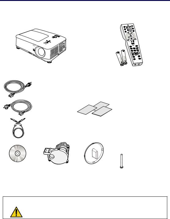
What’s in the Box?
Carefully unpack the projector and check that the following items are included:
NP4100/NP4100W Projector
North America (AC 120V) (79TD5701)
Europe (AC 230V) (79TD5711)
Remote Cable 10m/33ft (79TD5481)
CD-ROM |
6 Segment Color |
(This User’s manual) |
Wheel |
(79TD6131) |
(79TD5371) |
Remote Control (79TD5521) (with Two AA alkaline batteries)
Lens Hole Cap
(Installed)
Quick setup guide (79TD6151) Important Information (79TD6141)
For North America Only: Registration Card Limited Warranty
For customers in Europe: You will find our current valid Guarantee Policy on our Web Site: www.nec-display-solutions.com
Anti-Theft Screw for lens x 1 (79TD5811) Security Sticker
Contact your dealer immediately if any items are missing, appear damaged, or if the unit does not work.
CAUTION
Avoid using the projector in dusty environments.
1

1. Introduction
Introduction to the Projector
Features you’ll enjoy:
DLP projector with high resolution Native WXGA support (NP4100W only)
A WXGA (1280 x 800) resolution provides wide screen display with an aspect ratio of 16:10.
High brightness
High brightness output of 6200 and 5500 lumens (NP4100 and NP4100W respectively) is achieved using the 4-segment color wheel.
Dual Lamp system
Two lamp system offers increased lamp life and energy savings along with redundancy. Extensive optional lens with bayonet mount
Five types of optional lenses are available.
Powered Lens Shift, Zoom, and Focus offer installation flexibility
Powered Horizontal and Vertical lens shift provides the ability to project from off center screen installations. Powered zoom and focus provide quick and easy adjustment.
Direct Power Off and Auto Power On
The projector has a feature called “Direct Power Off”. This feature allows the projector to be turned off (even when projecting an image) using a power strip equipped with a switch and a breaker.
Note:
Before using Direct Power Off, be sure to allow at least 20 minutes immediately after turning on the projector and starting to display an image.
Also, the power cable can be removed immediately after turning off the projector. Auto Start eliminates the need to always use the POWER (ON/STANDBY) button on the remote control or projector cabinet.
A variety of input ports and a comprehensive array of system control interfaces
This projector supports input signals including BNC, DVI-D, analog RGB, component, S-video, and composite.
3W+3W Stereo speaker
Built in 3W x 2 speakers are provided. Preventing unauthorized use of the projector
Enhanced smart security settings for password protection, cabinet control panel lock to help prevent unauthorized access, adjustments and theft deterrence.
Integrated RJ-45 connector for wired networking capability for property management.
Combination of BrilliantColor™ and 6-segment color wheel offers a more true color reproduction
2
1. Introduction
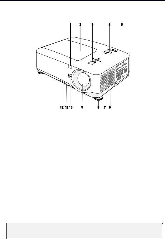
Part Names of the Projector
Front-right view
|
|
|
|
|
|
|
|
|
|
|
|
|
ITEM |
|
|
LABEL |
|
|
DESCRIPTION |
|
|
SEE PAGE: |
|
|
|
|
|
|
|
|
|
|
|
|
|
|
1. |
|
|
IR receiver |
|
|
Receiver for IR signal from remote control |
|
12 |
|
|
|
2. |
|
|
Lamp cover |
|
|
Remove cover to replace lamp or color wheel |
|
112 |
|
|
|
3. |
|
|
Lens control panel |
|
|
See Lens Controls |
|
7 |
|
|
|
|
|
|
|
|
|
|
|
|
|
|
|
4. |
|
|
OSD control panel |
|
|
See OSD Controls and Status LEDS |
|
8 |
|
|
|
|
|
|
|
|
|
|
|
|
|
|
|
5. |
|
|
I/O connector panel |
|
|
Connect various input devices |
|
10 |
|
|
|
6. |
|
|
Intake vent |
|
|
Lamp cooling vent – do not obstruct |
|
|
— |
|
|
7. |
|
|
Speakers |
|
|
Built-in stereo speakers |
|
|
— |
|
|
8. |
|
|
Height adjuster |
|
|
Adjusts level of projector |
|
6, 45 |
|
|
|
9. |
|
|
Lens |
|
|
Remove lens hole cap before use |
|
|
— |
|
|
10. |
|
|
Lens release button |
|
|
Press the release button before removing the |
|
|
— |
|
|
|
|
|
|
lens |
|
|
|
|||
|
|
|
|
|
|
|
|
|
|
|
|
|
11. |
|
|
Anti-Theft Screw |
|
|
Prevent theft of the lens |
|
|
— |
|
|
12. |
|
|
Intake vent and front |
|
|
Keeps the front fan free of dust |
|
108 |
|
|
|
|
|
|
|
– clean regularly for optimum performance |
|
|
||||
|
|
|
filter |
|
|
|
|
||||
|
|
|
|
|
|
– do not obstruct |
|
|
|
|
|
|
|
|
|
|
|
|
|
|
|
|
|
Important:
Grill openings on the projector allow for good air circulation, which keeps the projector lamp cool. Do not obstruct any of the grill openings.
3
1. Introduction
Top View
|
|
|
|
|
|
|
|
|
|
|
|
|
|
ITEM |
|
|
LABEL |
|
|
|
DESCRIPTION |
|
|
SEE PAGE: |
|
|
|
|
|
|
|
|
|
|
|
|
|
|
|
1. |
|
|
Lens control panel |
|
|
See Lens3 |
Controls |
|
7 |
|
|
|
|
|
|
|
|
|
|
|
|
|
|
|
|
2. |
|
|
Right-hand speaker |
|
|
Right-hand speaker |
|
|
— |
|
|
|
|
|
|
|
|
|
|
|
|
|
||
|
3. |
|
|
Lamp cover |
|
|
Remove cover to replace lamp or color wheel |
|
112 |
|
||
|
|
|
|
|
|
|
|
|
|
|
|
|
|
4. |
|
|
Exhaust vent |
|
|
Exhaust vent – do not obstruct |
|
|
— |
|
|
|
|
|
|
|
|
|
|
|
|
|
|
|
|
5. |
|
|
OSD control panel |
|
|
See OSD3 |
Controls and Status LEDS |
|
8 |
|
|
|
|
|
|
|
|
|
|
|
|
|
|
|
|
6. |
|
|
Rear intake vent |
|
|
Rear cooling intake – do not obstruct |
|
|
— |
|
|
|
|
|
|
|
|
|
|
|
|
|
|
|
|
7. |
|
|
Left intake vent |
|
|
Left-hand cooling intake – do not obstruct |
|
|
— |
|
|
|
|
|
|
|
|
|
|
|
|
|
|
|
4
1. Introduction
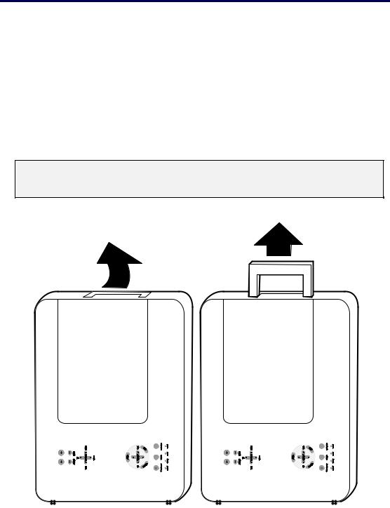
Carrying the Projector
Always carry your projector by the handle.
Before moving or carrying the projector, disconnect the power cable and any other cables that may be attached to it.
When moving the projector or when the projector is not in use, cover the lens with the lens cap.
To extend the projector handle, refer to the following guide.
1. Stand the projector on its end with the control panels at the bottom.
Note:
Stand the projector on its end by lifting the cabinet. Do not use the handle to place the projector upright.
2. Lift the handle in the direction shown until it is fully extended.
5 |
1. Introduction
Bottom view
|
|
|
|
|
|
|
|
|
|
|
|
|
|
|
|
|
|
|
|
|
|
|
|
|
|
|
|
|
|
|
|
|
|
|
|
|
|
|
|
|
|
|
|
|
|
|
|
|
|
|
|
|
|
|
|
|
|
|
|
|
|
|
|
|
|
|
|
|
|
|
|
|
|
|
|
|
|
|
|
|
|
|
|
|
|
|
|
|
|
|
|
|
|
|
|
|
|
|
|
|
|
|
|
|
|
|
|
|
|
|
|
|
|
|
|
|
|
|
|
|
|
|
|
|
|
|
|
|
|
|
|
|
|
|
|
|
|
|
|
|
|
|
|
|
|
|
|
|
|
|
|
|
|
|
|
|
|
|
|
|
|
|
|
|
|
|
|
|
|
|
|
|
|
|
|
|
|
|
|
|
|
|
|
|
|
|
|
|
|
|
|
|
|
|
|
|
|
|
|
|
|
|
|
|
|
|
|
|
|
|
|
|
|
|
|
|
|
|
|
|
|
|
|
|
|
|
|
|
|
|
|
|
|
|
|
|
|
|
|
|
|
|
|
|
|
|
|
|
|
|
|
|
|
|
|
|
|
|
|
|
|
|
|
|
|
|
|
|
|
|
|
|
|
|
|
|
|
|
|
|
|
|
|
|
|
|
|
|
|
|
|
|
|
|
|
|
|
|
|
|
|
|
|
|
|
|
|
|
|
|
|
|
|
|
|
|
|
|
|
|
|
|
|
|
|
|
|
|
|
|
|
|
|
|
|
|
|
|
|
|
|
|
|
|
|
|
|
|
|
|
|
|
|
|
|
|
|
|
|
|
|
|
|
|
|
|
|
|
|
|
|
|
|
|
|
|
|
|
|
|
|
|
|
|
|
|
|
|
|
|
|
|
|
|
|
|
|
|
|
|
|
|
|
|
|
|
|
|
|
|
|
|
|
|
|
|
|
|
|
|
|
|
|
|
|
|
|
|
|
|
|
|
|
|
|
|
|
|
|
|
|
|
|
|
|
|
|
|
|
|
|
|
|
|
|
|
|
|
|
|
|
|
|
|
|
|
|
|
|
|
|
|
|
|
|
|
|
|
|
|
|
|
|
|
|
|
|
|
|
|
|
|
|
|
|
|
|
|
|
|
|
|
|
|
|
|
|
|
|
|
|
|
|
|
|
|
|
|
|
|
|
|
|
|
|
|
|
|
|
|
|
|
|
|
|
|
|
|
|
|
|
|
|
|
|
|
|
|
|
|
|
|
|
|
|
|
|
|
|
|
|
|
|
|
|
|
|
|
|
|
|
|
|
|
|
|
|
|
|
|
|
|
|
|
|
|
|
|
|
|
|
|
|
|
|
|
|
|
|
|
|
|
|
|
|
|
|
|
|
|
|
|
|
|
|
|
|
|
|
|
|
|
|
|
|
|
|
|
|
|
|
|
|
|
|
|
|
|
|
|
|
|
|
|
|
|
|
|
|
|
|
|
|
|
|
|
|
|
|
|
|
|
|
|
|
|
|
|
|
|
|
|
|
|
|
|
|
|
|
|
|
|
|
|
|
|
|
|
|
|
|
|
|
|
|
|
|
|
|
|
|
|
|
|
|
|
|
|
|
|
|
|
|
|
|
|
|
|
|
|
|
|
|
|
|
|
|
|
|
|
|
|
|
|
|
|
|
|
|
|
|
|
|
|
|
|
|
|
|
|
|
|
|
|
|
|
|
|
|
|
|
|
|
|
|
|
|
|
|
|
|
|
|
|
|
|
|
|
|
|
|
|
|
|
|
|
|
|
|
|
|
|
|
|
|
|
|
|
|
|
|
|
|
|
|
|
|
|
|
|
|
|
|
|
|
|
|
|
|
|
|
|
|
|
|
|
|
|
|
|
|
|
|
|
|
|
|
|
|
|
|
|
|
|
|
|
|
|
|
|
|
|
|
|
|
|
|
|
|
|
|
|
|
|
|
|
|
|
|
|
|
|
|
|
|
|
|
|
|
|
|
|
|
|
|
|
|
|
|
|
|
|
|
|
|
|
|
|
|
|
|
|
|
|
|
|
|
|
|
|
|
|
|
|
|
|
|
|
|
|
|
|
|
|
ITEM |
|
|
|
LABEL |
|
|
|
|
|
|
|
|
|
|
|
|
DESCRIPTION |
|
|
SEE PAGE: |
|
|||||||||||||||||||||
|
|
|
|
|
|
|
|
|
|
|
|
|
|
|
|
|
|
|
|
|
|
|
|
|
|
|
|||||||||||||||||
|
1. |
|
|
Height adjusters |
|
|
Adjust projection height |
|
45 |
|
|
||||||||||||||||||||||||||||||||
|
|
|
|
|
|
|
|
|
|
|
|
|
|
|
|
|
|
|
|
|
|
|
|
|
|
|
|
||||||||||||||||
|
2. |
|
|
Intake vent |
|
|
Color wheel cooling vent – do not obstruct |
|
|
— |
|
||||||||||||||||||||||||||||||||
|
|
|
|
|
|
|
|
|
|
|
|
|
|
|
|
|
|
|
|
|
|
|
|
|
|
|
|
|
|
|
|
||||||||||||
|
3. |
|
|
Front filter |
|
|
Keep the fan free of dust – clean regularly for |
|
108 |
|
|
||||||||||||||||||||||||||||||||
|
|
|
|
|
optimum performance |
|
|
|
|||||||||||||||||||||||||||||||||||
|
|
|
|
|
|
|
|
|
|
|
|
|
|
|
|
|
|
|
|||||||||||||||||||||||||
|
|
|
|
|
|
|
|
|
|
|
|
|
|
|
|
|
|
|
|
|
|
|
|
|
|
|
|
|
|
|
|
||||||||||||
|
4. |
|
|
Ceiling support holes |
|
|
Contact your dealer for information on |
|
|
— |
|
||||||||||||||||||||||||||||||||
|
|
|
|
|
mounting the projector on a ceiling |
|
|
|
|||||||||||||||||||||||||||||||||||
|
|
|
|
|
|
|
|
|
|
|
|
|
|
|
|
|
|
|
|||||||||||||||||||||||||
|
|
|
|
|
|
|
|
|
|
|
|
|
|
|
|
|
|
|
|
|
|
|
|
|
|
|
|
||||||||||||||||
|
5. |
|
|
Security chain |
|
|
Attach anti-theft device – |
|
61 |
|
|
||||||||||||||||||||||||||||||||
|
|
|
opening |
|
|
see Using the Physical Lock |
|
|
|
||||||||||||||||||||||||||||||||||
|
|
|
|
|
|
|
|
|
|
|
|
||||||||||||||||||||||||||||||||
|
|
|
|
|
|
|
|
|
|
|
|
|
|
|
|
|
|
|
|
|
|
|
|
|
|
|
|
|
|
|
|
|
|
|
|
|
|
|
|
||||
|
6. |
|
|
Rear filter |
|
|
Keep the fans free of dust – |
|
108 |
|
|
||||||||||||||||||||||||||||||||
|
|
|
|
|
|
|
|
|
|
|
|
|
|
|
|
|
|||||||||||||||||||||||||||
|
7. |
|
|
Side filter |
|
|
clean regularly for optimum performance |
|
|
|
|||||||||||||||||||||||||||||||||
|
|
|
|
|
|
|
|
|
|
||||||||||||||||||||||||||||||||||
|
|
|
|
|
|
|
|
|
|
|
|
|
|
|
|
|
|
|
|
|
|
|
|
|
|
|
|
|
|
|
|
|
|
|
|||||||||
|
|
|
|
|
|
|
|
|
|
|
|
|
|
|
|
|
|
|
|
|
|
|
|
|
|||||||||||||||||||
|
|
|
|
|
|
|
|
|
|
|
|
|
|
|
|
|
|
|
|
|
|
|
|||||||||||||||||||||
|
|
CAUTION |
With ceiling installation, use approved mounting hardware & M4 screws; |
|
|
||||||||||||||||||||||||||||||||||||||
|
|
maximum depth of screw: 12 mm; distance from ceiling/ wall: 50/50 cm, |
|
|
|||||||||||||||||||||||||||||||||||||||
|
|
|
|
|
|
20/20 inch for proper ventilation; distance from fluorescent lamps: at least |
|
|
|||||||||||||||||||||||||||||||||||
|
|
|
|
|
|
50 cm front and back of then projector. For permanent installations, follow |
|
|
|||||||||||||||||||||||||||||||||||
|
|
|
|
|
|
local codes. |
|
|
|
|
|
|
|
|
|
|
|
|
|
|
|
|
|
|
|
|
|
|
|
|
|
|
|
|
|
|
|
|
|||||
|
|
|
|
|
|
|
|
|
|
|
|
|
|
|
|
|
|
|
|
|
|
|
|
|
|
|
|
|
|
|
|
|
|
|
|
|
|
|
|
|
|
|
|
6
1. Introduction
Top Features
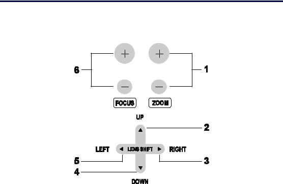
Lens Controls
|
|
|
|
|
|
|
|
|
|
|
|
|
ITEM |
|
|
LABEL |
|
|
DESCRIPTION |
|
|
SEE PAGE: |
|
|
|
|
|
|
|
|
|
|
|
|
|
|
1. |
|
|
ZOOM |
|
|
Increase/decrease projected image size |
|
51 |
|
|
|
|
|
|
|
|
|
|
|
|
|
|
|
2. |
|
|
UP CURSOR |
|
|
|
|
|
|
|
|
|
|
|
|
|
|
|
|
|
|
|
|
3. |
|
|
RIGHT CURSOR |
|
|
Move image left, right, up, or down |
|
|
|
|
|
|
|
|
|
|
|
|
|
|
|
|
|
4. |
|
|
DOWN CURSOR |
|
|
|
|
|
|
|
|
|
|
|
|
|
|
|
|
|
||
|
|
|
|
|
|
|
|
|
|
|
|
|
5. |
|
|
LEFT CURSOR |
|
|
|
|
|
|
|
|
|
|
|
|
|
|
|
|
|
||
|
6. |
|
|
FOCUS |
|
|
Focus the projected image |
|
51 |
|
|
|
|
|
|
|
|
|
|
|
|
|
|
7
1. Introduction
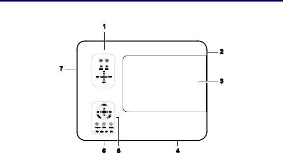
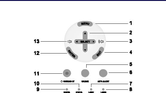
OSD Controls and Status LEDS
|
|
|
|
|
|
|
|
|
|
|
|
|
|
ITEM |
|
|
LABEL |
|
|
|
DESCRIPTION |
|
|
SEE PAGE: |
|
|
|
|
|
|
|
|
|
|
|
|
|
|
|
1. |
|
|
MENU |
|
|
Open / Close the OSD |
|
62 |
|
||
|
|
|
|
|
|
|
|
|
|
|
|
|
|
2. |
|
|
SELECT PAD |
|
|
Navigate and change settings in the OSD |
|
62 |
|
||
|
|
|
|
|
|
|
|
|
|
|
|
|
|
3. |
|
|
RIGHT CURSOR/ |
|
|
|
|
|
47 |
|
|
|
|
|
VOLUME |
|
|
Increase volume |
|
|
||||
|
|
|
|
INCREASE |
|
|
|
|
|
|
|
|
|
|
|
|
|
|
|
|
|
|
|
|
|
|
4. |
|
|
EXIT |
|
|
Exit the On-Screen Display (OSD) |
|
63 |
|
||
|
|
|
|
|
|
|
|
|
|
|
|
|
|
5. |
|
|
SOURCE |
|
|
Change or select the input device |
|
40 |
|
||
|
|
|
|
|
|
|
|
|
|
|
|
|
|
6. |
|
|
AUTO ADJUST |
|
|
Optimize image size, position, and resolution |
|
46 |
|
||
|
|
|
|
|
|
|
|
|
|
|
|
|
|
|
|
|
|
|
|
Green |
|
|
|
|
|
|
7. |
|
|
LAMP 1 |
|
|
|
See Indicator Messages |
|
118 |
|
|
|
|
|
|
|
Flashing |
|
||||||
|
|
|
|
|
|
|
|
|
|
|
|
|
|
|
|
|
|
|
|
|
|
|
|
|
|
8
|
|
|
|
|
|
|
|
|
1. Introduction |
|
|
|||
|
|
|
|
|
|
|
|
|
|
|
|
|
||
|
|
|
|
|
|
|
|
|
|
|
|
|
|
|
|
ITEM |
LABEL |
|
|
|
DESCRIPTION |
SEE PAGE: |
|
||||||
|
|
|
|
|
|
|
|
|
|
|
|
|
|
|
|
|
|
|
|
|
|
|
Green |
|
|
|
|
|
|
|
8. |
|
|
LAMP 2 |
|
|
|
See Indicator Messages |
|
118 |
|
|
||
|
|
|
|
|
Flashing |
|
|
|||||||
|
|
|
|
|
|
|
|
|
|
|
|
|
|
|
|
|
|
|
|
|
|
|
|
|
|
|
|
|
|
|
|
|
|
|
|
|
|
Green |
|
|
|
|
|
|
|
9. |
|
|
POWER (LED) |
|
|
|
See Indicator Messages |
|
117 |
|
|
||
|
|
|
|
|
Orange |
|
|
|
||||||
|
|
|
|
|
|
|
|
|
|
|
|
|
|
|
|
|
|
|
|
|
|
|
Flashing |
|
|
|
|
|
|
|
|
|
|
|
|
|
|
|
|
|
|
|
|
|
|
10. |
|
|
STATUS (LED) |
|
|
Green |
Lamp ready you can safely turn |
|
117 |
|
|
||
|
|
|
|
|
on or off the projector |
|
|
|
||||||
|
|
|
|
|
|
|
|
|
|
|
|
|
|
|
|
|
|
|
|
|
|
|
|
|
|
|
|
|
|
|
11. |
|
|
ON/STAND BY |
|
|
Turn the projector on or off |
|
10, 38 |
|
|
|||
|
|
|
|
|
(main power switch must be turned on first) |
|
|
|
||||||
|
|
|
|
|
|
|
|
|
|
|
|
|
||
|
|
|
|
|
|
|
|
|
|
|
|
|||
|
12. |
|
|
ENTER |
|
|
Select or change settings in the OSD |
|
62 |
|
|
|||
|
|
|
|
|
|
|
|
|
|
|
|
|
|
|
|
13. |
|
|
LEFT |
|
|
Decrease volume |
|
47 |
|
|
|||
|
|
|
CURSOR/VOLUME |
|
|
|
|
|
||||||
|
|
|
|
|
DECREASE |
|
|
|
|
|
|
|
|
|
|
|
|
|
|
|
|
|
|
|
|
|
|
|
|
9
1. Introduction
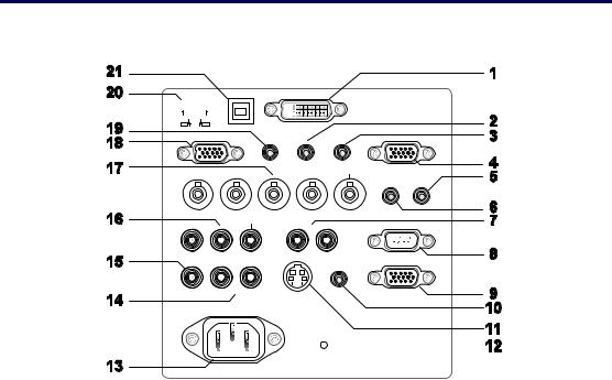
Terminal Panel Features
|
|
|
|
|
|
|
|
|
|
|
|
|
|
|
|
|
|
|
|
|
|
|
|
|
|
|
|
|
|
|
|
|
|
|
|
|
|
|
|
|
|
|
|
|
|
|
|
|
|
|
|
|
|
|
|
|
|
|
|
|
|
|
|
|
|
|
|
|
|
|
|
|
|
|
|
|
|
|
|
|
|
|
|
|
|
|
|
|
|
|
|
|
|
|
|
|
|
|
|
|
|
|
|
|
|
|
|
|
|
|
|
|
|
|
|
|
|
|
|
|
|
|
|
|
|
|
|
|
|
|
|
|
|
|
|
|
|
|
|
|
|
|
|
|
|
|
|
|
|
|
|
|
|
|
|
|
|
|
|
|
|
|
|
|
|
|
|
|
|
|
|
|
|
|
|
|
|
|
|
|
|
|
|
|
|
|
|
|
|
|
|
|
|
|
|
|
|
|
|
|
|
|
|
|
|
|
|
|
|
|
|
|
|
|
|
|
|
|
|
|
|
|
|
|
|
|
|
|
|
|
|
|
|
|
|
|
|
|
|
|
|
|
|
|
|
|
|
|
|
|
|
|
|
|
|
|
|
|
|
|
|
|
|
|
|
|
|
|
|
|
|
|
|
|
|
|
|
|
|
|
|
|
|
|
|
|
|
|
|
|
|
|
|
|
|
|
|
|
|
|
|
|
|
|
|
|
|
|
|
|
|
|
|
|
|
|
|
|
|
|
|
|
|
|
|
|
|
|
|
|
|
|
|
|
|
|
|
|
|
|
|
|
|
|
|
|
|
|
|
|
|
|
|
|
|
|
|
|
|
|
|
|
|
|
|
|
|
|
|
|
|
|
|
|
|
|
|
|
|
|
|
|
|
|
|
|
|
|
|
|
|
|
|
|
|
|
|
|
|
|
|
|
|
|
|
|
|
|
|
|
|
|
|
|
|
|
|
|
|
|
|
|
|
|
|
|
|
|
|
|
|
|
|
|
|
|
|
|
|
|
|
|
|
|
|
|
|
|
|
|
|
|
|
|
|
|
|
|
|
|
|
|
|
|
|
|
|
|
|
|
|
|
|
|
|
|
|
|
|
|
|
|
|
|
|
|
|
|
|
|
|
|
|
|
|
|
|
|
|
|
|
|
|
|
|
|
|
|
|
|
|
|
|
|
|
|
|
|
|
|
|
|
|
|
|
|
|
|
|
|
|
|
|
|
|
|
|
|
|
|
|
|
|
|
|
|
|
|
|
|
|
|
|
|
|
|
|
|
|
|
|
|
|
|
|
|
|
|
|
|
|
|
|
|
|
|
|
|
|
|
|
|
|
|
|
|
|
|
|
|
|
|
|
|
|
|
|
|
|
|
|
|
|
|
|
|
|
|
|
|
|
|
|
|
|
|
|
|
|
|
|
|
|
|
|
|
|
|
|
|
|
|
|
|
|
|
|
|
|
|
|
|
|
|
|
|
|
|
|
|
|
|
|
|
|
|
|
|
|
|
|
|
|
|
|
|
|
|
|
|
|
|
|
|
|
|
|
|
|
|
|
|
|
|
|
|
|
|
|
|
|
|
|
|
|
|
|
|
|
|
|
|
|
|
|
|
|
|
|
|
|
|
|
|
|
|
|
|
|
|
|
|
|
|
|
|
|
|
|
|
|
|
|
|
|
|
|
|
|
|
|
|
|
|
|
|
|
|
|
|
|
|
|
|
|
|
|
|
|
|
|
|
|
|
|
|
|
|
|
|
|
|
|
|
|
|
|
|
|
|
|
|
|
|
|
|
|
|
|
|
|
|
|
|
|
|
|
|
|
|
|
|
|
|
|
|
|
|
|
|
|
|
|
|
|
|
|
|
|
|
|
|
|
|
|
|
|
|
|
|
|
|
|
|
|
|
|
|
|
|
|
|
|
|
|
|
ITEM |
|
|
LABEL |
|
|
|
|
|
|
|
|
|
|
|
|
|
|
|
|
|
|
DESCRIPTION |
|
|
SEE PAGE: |
|
|||||||||||||||||||
|
|
|
|
|
|
|
|
|
|
|
|
|
|
|
|
|
|
|
|
|
|
|
|
|
|
|
|
|
|
|||||||||||||||||
|
1. |
|
|
COMPUTER 3 IN |
|
Connect the DVI cable (not supplied) from a |
|
31 |
|
|||||||||||||||||||||||||||||||||||||
|
|
|
|
computer |
|
|
||||||||||||||||||||||||||||||||||||||||
|
|
|
|
|
|
|
|
|
|
|
|
|
|
|
|
|
|
|
|
|
|
|
|
|
||||||||||||||||||||||
|
|
|
|
|
|
|
|
|
|
|
|
|
|
|
|
|
|
|
|
|
|
|
|
|
|
|
|
|
|
|||||||||||||||||
|
2. |
|
|
AUDIO IN (3) |
|
Connect the audio cable (not supplied) from |
|
|
— |
|
||||||||||||||||||||||||||||||||||||
|
|
|
|
the input device |
|
|
|
|||||||||||||||||||||||||||||||||||||||
|
|
|
|
|
|
|
|
|
|
|
|
|
|
|
|
|
|
|
|
|
|
|
|
|
||||||||||||||||||||||
|
|
|
|
|
|
|
|
|
|
|
|
|
|
|
|
|||||||||||||||||||||||||||||||
|
3. |
|
|
AUDIO OUT |
|
Audio loop-thru |
|
|
— |
|
||||||||||||||||||||||||||||||||||||
|
|
|
|
|
|
|
|
|
|
|
|
|
|
|
|
|||||||||||||||||||||||||||||||
|
4. |
|
|
MONITOR OUT |
|
Connect to a monitor |
|
|
— |
|
||||||||||||||||||||||||||||||||||||
|
|
|
|
|
|
|
|
|
|
|
|
|
|
|
||||||||||||||||||||||||||||||||
|
5. |
|
|
REMOTE 2 |
|
Connect the remote to the projector |
|
16 |
|
|||||||||||||||||||||||||||||||||||||
|
|
|
|
|
|
|
|
|
|
|
|
|
|
|
|
|
|
|
|
|
|
|
|
|
|
|
|
|
|
|||||||||||||||||
|
6. |
|
|
AUDIO IN (2) |
|
Connect the audio cable (not supplied) from |
|
|
— |
|
||||||||||||||||||||||||||||||||||||
|
|
|
|
the input device |
|
|
|
|||||||||||||||||||||||||||||||||||||||
|
|
|
|
|
|
|
|
|
|
|
|
|
|
|
|
|
|
|
|
|
|
|
|
|
||||||||||||||||||||||
|
|
|
|
|
|
|
|
|
|
|
|
|
|
|
|
|||||||||||||||||||||||||||||||
|
7. |
|
|
L/MONO, R |
|
Connect an RCA audio cables (not supplied) |
|
|
— |
|
||||||||||||||||||||||||||||||||||||
|
|
|
(COMPONENT) |
|
from the input device right and left channels |
|
|
|
||||||||||||||||||||||||||||||||||||||
|
|
|
|
|
|
|
|
|
||||||||||||||||||||||||||||||||||||||
|
|
|
|
|
|
|
|
|
|
|
|
|
|
|
||||||||||||||||||||||||||||||||
|
8. |
|
|
PC CONTROL |
|
Installation control |
|
131 |
|
|||||||||||||||||||||||||||||||||||||
|
|
|
|
|
|
|
|
|
|
|
|
|
|
|
||||||||||||||||||||||||||||||||
|
9. |
|
|
REMOTE 1 |
|
For external control |
|
139 |
|
|||||||||||||||||||||||||||||||||||||
|
|
|
|
|
|
|
|
|
|
|
|
|
|
|
|
|
|
|
|
|
|
|
|
|
|
|
|
|
|
|
|
|
|
|
|
|
|
|
|
|
|
|
|
|
|
|
10

1. Introduction
|
|
|
|
|
|
|
|
|
|
|
|
|
ITEM |
|
|
LABEL |
|
|
DESCRIPTION |
|
|
SEE PAGE: |
|
|
|
|
|
|
|
|
|
|
|
|
|
|
|
|
|
|
|
|
When connected to the screen through a |
|
|
|
|
|
10. |
|
|
SC TRIGGER |
|
|
commercially available cable, the screen de- |
|
133 |
|
|
|
|
|
|
|
ploys automatically on start up of the |
|
|
||||
|
|
|
|
|
|
|
projector. The screen retracts when the pro- |
|
|
|
|
|
|
|
|
|
|
|
jector is powered off (see notes below) |
|
|
|
|
|
|
|
|
|
|
|
|
|
|
|
|
|
11. |
|
|
S-VIDEO |
|
|
Connect a commercially available S-video |
|
35 |
|
|
|
|
|
|
|
cable from a video device |
|
|
||||
|
|
|
|
|
|
|
|
|
|
|
|
|
|
|
|
|
|
|
|
|
|
|
|
|
12. |
|
|
POWER SWITCH |
|
|
Turn on/off the projector |
|
38, 48 |
|
|
|
|
|
|
|
|
|
|
|
|
|
|
|
13. |
|
|
AC IN |
|
|
Connect the supplied power cable |
|
37 |
|
|
|
|
|
|
|
|
|
|
|
|
|
|
|
14. |
|
|
L/MONO, R |
|
|
Connect RCA audio cables (not supplied) |
|
|
— |
|
|
|
|
|
|
from the input device right and left channels. |
|
|
|
|||
|
|
|
|
|
|
|
This audio jack is shared with S-Video input. |
|
|
|
|
|
|
|
|
|
|
|
|
|
|
|
|
|
15. |
|
|
VIDEO IN |
|
|
Connect a composite video cable (not sup- |
|
35 |
|
|
|
|
|
|
|
plied) from a video device to the yellow RCA |
|
|
||||
|
|
|
|
|
|
|
jack |
|
|
|
|
|
|
|
|
|
|
|
|
|
|
|
|
|
16. |
|
|
COMPONENT IN |
|
|
Connect a component video enabled device |
|
34 |
|
|
|
|
|
(Y, Cb/Pb, Cr/Pr) |
|
|
|
|
||||
|
|
|
|
|
|
|
|
|
|
|
|
|
|
|
|
|
|
|
|
|
|
|
|
|
17. |
|
|
COMPUTER 2 IN |
|
|
Connect RGBHV or Component signal from |
|
31 |
|
|
|
|
|
(R/Cr, G/Y, B/Cb, |
|
|
|
|
||||
|
|
|
|
|
computer or component video enabled device |
|
|
||||
|
|
|
|
H, V) |
|
|
|
|
|
|
|
|
|
|
|
|
|
|
|
|
|
|
|
|
|
|
|
|
|
|
|
|
|
|
|
|
18. |
|
|
COMPUTER 1 IN |
|
|
Connect a VGA cable (not supplied) from a |
|
31 |
|
|
|
|
|
|
|
computer |
|
|
||||
|
|
|
|
|
|
|
|
|
|
|
|
|
|
|
|
|
|
|
|
|
|
|
|
|
19. |
|
|
AUDIO IN (1) |
|
|
Connect the audio cable (not supplied) from |
|
|
— |
|
|
|
|
|
|
the input device |
|
|
|
|||
|
|
|
|
|
|
|
|
|
|
|
|
|
|
|
|
|
|
|
|
|
|
|
|
|
20. |
|
|
LAN |
|
|
Connect a LAN cable (not supplied) from a |
|
103 |
|
|
|
|
|
|
|
computer |
|
|
||||
|
|
|
|
|
|
|
|
|
|
|
|
|
|
|
|
|
|
|
|
|
|
|
|
|
21. |
|
|
SERVICE |
|
|
Connect the USB cable (not supplied) from a |
|
|
— |
|
|
|
|
|
|
computer. For service personnel only. |
|
|
|
|||
|
|
|
|
|
|
|
|
|
|
|
|
|
|
|
|
|
|
|
|
|
|
|
|
Note:
To use this feature, you must turn on the Screen Trigger function on OSD. Screen controllers are supplied and supported by screen manufacturers.
Do not use this jack for anything other than intended use. Connecting the wired remote control to the Trigger mini jack causes damage to the remote control.
11

1. Introduction
Part Names of the Remote Control
The Remote Control unit supplied with the projector combines ergonomic design and utility and includes features such as Volume and Zoom Control, Freeze Frame and a useful pointing tool in the form of a laser. Refer to the following diagram and table for button location and functionality.
|
|
|
|
|
|
|
|
|
|
|
|
|
|
|
ITEM |
|
|
LABEL |
|
|
|
|
|
|
|
|
|
|
|
|
|
|
|
|
|
|
|
|
|
|
|
|
1. |
|
|
Remote jack |
|
|
|
|
|
|
|
|
|
|
2. |
|
|
Laser pointer |
|
|
|
|
|
|
|
|
|
|
3. |
|
|
Infrared transmitter |
|
|
|
|
|
|
|
|
|
|
4. |
|
|
LED |
|
|
|
|
|
|
|
|
|
|
5. |
|
|
Power OFF button* |
|
|
|
|
|
|
|
|
|
|
6. |
|
|
Power ON button** |
|
|
|
|
|
|
|
|
|
|
|
|
|
|
|
|
|
|
|
|
|
||
|
7. |
|
|
Computer 1 button |
|
|
|
|
|
|
|
|
|
|
|
|
|
|
|
|
|
|
|
|
|
||
|
8. |
|
|
Computer 2 button |
|
|
|
|
|
|
|
|
|
|
9. |
|
|
Video button |
|
|
|
|
|
|
|
|
|
|
|
|
|
|
|
|
|
|
|
|
|
|
|
|
|
|
|
Viewer button |
|
|
|
|
|
|
|
|
|
|
|
|
|
(The VIEWER and |
|
|
|
|
|
|
|
|
|
|
|
|
|
PAGE buttons will |
|
|
|
|
|
|
|
|
|
|
10. |
|
|
work with the other |
|
|
|
|
|
|
|
|
|
|
|
|
|
|
|
|
|
|
|
|
|
||
|
|
|
models, which have a |
|
|
|
|
|
|
|
|
|
|
|
|
|
|
Viewer function. |
|
|
|
|
|
|
|
|
|
|
|
|
|
NP4100/NP4100W |
|
|
|
|
|
|
|
|
|
|
|
|
|
does not have this |
|
|
|
|
|
|
|
|
|
|
|
|
|
function). |
|
|
|
|
|
|
|
|
|
|
11. |
|
|
Component button |
|
|
|
|
|
|
|
|
|
|
12. |
|
|
Computer 3 button |
|
|
|
|
|
|
|
|
|
|
|
|
|
|
|
|
|
|
|
|
|
|
|
|
13. |
|
|
S-Video button |
|
|
|
|
|
|
|
|
|
|
|
|
|
|
|
|
|
|
|
|
|
|
|
|
14. |
|
|
LAN button |
|
|
|
|
|
|
|
|
|
|
|
|
(Not available on |
|
|
|
|
|
|
|
|
|
|
|
|
|
|
NP4100/NP4100W) |
|
|
|
|
|
|
|
|
|
|
15. |
|
|
Menu button |
|
|
|
|
|
|
|
|
|
|
|
|
|
|
|
|
|
|
|
|
|
|
|
|
16. |
|
|
Select ▲▼◄► |
|
|
|
|
|
|
|
|
|
|
|
|
button |
|
|
|
|
|
|
|
|
|
|
|
|
|
|
|
|
|
|
|
|
|
|
|
|
|
17. |
|
|
Enter button |
|
|
|
|
|
|
|
|
|
|
|
|
|
|
|
|
|
|
|
|
|
|
|
LABEL |
ITEM |
Exit button |
18. |
Laser button |
19. |
L-Click button |
20. |
R-Click button |
21. |
Focus/ Zoom button |
22. |
Freeze button |
23. |
Lens shift button |
24. |
Aspect button |
25. |
Lamp mode button |
26. |
Auto ADJ. button |
27. |
Volume buttons |
28. |
Magnify button |
29. |
(Not available on |
|
NP4100W) |
|
Page Up/Down buttons |
|
(The VIEWER and |
|
PAGE buttons will |
|
work with the other |
30. |
models, which have a |
|
Viewer function. |
|
NP4100/NP4100W |
|
does not have this func- |
|
tion). |
|
Picture button |
31. |
|
|
Keystone button |
32. |
|
|
PIC-Mute button |
33. |
|
|
Help button |
34. |
12

1. Introduction
Important:
1.Avoid using the projector with bright fluorescent lighting turned on. Certain highfrequency fluorescent lights can disrupt remote control operation.
2.Be sure nothing obstructs the path between the remote control and the projector. If the path between remote and projector is obstructed, you can bounce the remote signal off certain reflective surfaces such as projector screens.
3.The buttons and keys on the projector have the same functions as the corresponding buttons on the remote control. This user’s manual describes the functions based on the remote control.
Note:
*To turn off the projector, press the Power OFF button twice.
**To turn on the projector, press and hold the Power On button for a minimum of two seconds.
13
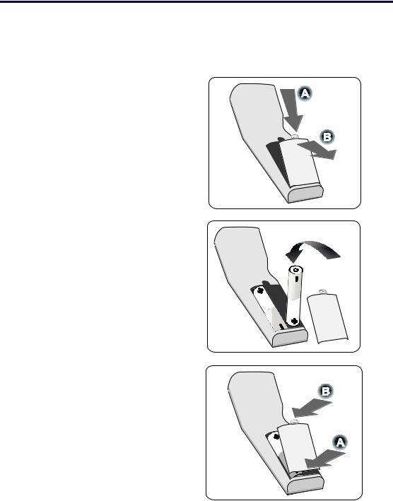
1. Introduction
Battery Installation
The Remote Control unit included with the projector does not contain batteries, though batteries are supplied as part of the complete package. To insert (or replace) the batteries, refer to the following guide.
1. Remove the battery compartment cover by squeezing the locking catch (A) and sliding the cover in the direction of the arrow (B).
2. Insert the supplied batteries taking note of the polarity (+/-) as shown.
3. Replace the cover locator (A), and then click locking catch into place (B).
14

1. Introduction
Operating Range for Wireless Remote Control
The infrared signal operates by line-of-sight up to a distance of about 22 feet (7m) and within a 60-degree angle of the remote sensor on the projector cabinet.
The projector will not respond if there are objects between the remote control and the sensor, or if strong light falls on the sensor. Weak batteries will also prevent the remote control from properly operating the projector.
Remote Control Precautions
The following precautions ensure that the remote operates correctly and safely.
Handle the remote control carefully.
If the remote control gets wet, wipe it dry immediately. Avoid excessive heat and humidity.
Do not heat, take apart, or throw batteries into fire.
For extended periods of inactivity, remove the batteries. Ensure that the batteries' polarity (+/–) aligned correctly.
Do not use new and old batteries together, or different types of batteries together.
Dispose of used batteries according to local regulations.
15
Loading...