


Nec PG9000, PG6000 user Manual
INTRODUCTION
Before operating this projector, please read this manual carefully and completely. This manual will provide you with the basic instructions for operation of the projector. Installation, preliminary adjustments and procedures which require the opening of the projector and contact with electrical components should be performed by service personnel. For continued safe and reliable operation, use only cables supplied by the manufacturer for power. Adhere to all notes and warnings.
Features
♦Multi scan circuit automatically locks on video, superdata from 15kHz to 61.lkHz (MultiSync 6PG) and graphics signals from 15kHz to 90kHz (MultiSync 9PG). You can interface video and high resolution RGB signals from various computers, workstations and graphics boards.
♦7” CRTs with deflection angle 90 degrees produce a detailed picture with a resolution of 1280 x 1024 pixels.
♦Impregnated cathode used in the CRTs makes possible 800 lumens of light output.
♦ECP lens produces an image with true color reproduction.
♦AKB circuit provides a stable white balance.
♦The wide band video circuit provides of 70MHz of Video Bandwidth.
♦Display size can be altered to accommodate any picture size from 60” to 300” diagonal. In addition to ceiling mounting, floor, desk top and rear installations are possible.
♦Digital point convergence provides high accuracy for a projecting fine graphic displays. (This can be purchased as an optional item for the MultiSync 6PG)
♦Easy accessing of adjustment item with on-screen menus.
♦Accepts up to 100 inputs with the ISS-6OlO/ISS-6OlOG.
♦Video system compatible with NTSC, PAL, SECAM and NTSC 4.43.
♦Up to 100 convergence patterns can be stored in the stand alone mode in digital memory.
♦Quick copy convergence for fast easy set up from one preset signal.
♦Built in self diagnostics for on sight troubleshooting.
♦Built in “CROSS HAIR”, “CROSS HATCH”, “DOT”, “WINDOW” and “H (FOCUS)” test patterns for accurate setup.
♦Source information status display.
♦The SEQUENCER function allows the projector to automatically select input signals one after another.

INTRODUCTION
Important Safeguards
The following are important safety instructions designed to ensure the long life of your projector and to prevent fire and shock hazards. Be sure to read these safety instructions carefully and follow all warnings given below.
Installation
Place the projector on a flat, level surface and in a dry area free from dust and moisture. Do not place the projector in direct sunlight, near stoves or other heat radiating appliances.
Smoke, steam and exposure to direct sunlight could adversely affect the internal components. Avoid rough handling when moving your equipment as a strong shock could damage
its internal components. If installing the projector on the ceiling, use only parts supplied by the manufacturer. Observe all instructions and warnings.
Power supply
The PG-6000 and PG-9000 projector are designed to operate on 120V 60H2, and the PG-6000G and PG-9000G are designed to operate on 220-240V 50Hz AC power supply.
Make sure your local power supply matches these requirements before operation. Handle the power cord carefully and avoid excessive bending. A damaged cord may
cause electric shock or fire. If the projector is not to be used for an extended period, remove the plug from the power outlet.
Cleaning
Unplug the projector from the power outlet before cleaning.
Clean the cabinet and front panel periodically with a soft cloth. If heavily stained, use a mild detergent solution. Never use strong detergents or solvents such as alcohol or thinner to clean your projector.
Lens cleaning: Avoid touching the lens surfaces. Special coating is applied to the lens surfaces. Consult your dealer for lens cleaning.
Fire and Shock Precautions
Adequate ventilation must be provided to prevent heat build-up inside the projector. Make sure the ventilation holes are unobstructed.
Keep the inside of the projector free from foreign objects, such as paper clips, nails, paper, etc. Do not attempt to retrieve such objects yourself or insert metal objects such as wire and screw-drivers inside the projector. If a hazardous object falls inside the projector, unplug it immediately and call a qualified electrical repairman for removal.
Do not set liquids on top of the projector.
PART NAMES AND FUNCTIONS
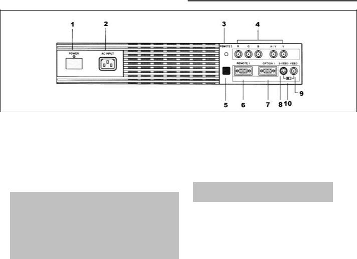
Terminal panel on the front
1.POWER Switch (Main power)
Press to turn the main power on. The STANDBY indicator is lit.
In this condition you can start up the projector by pressing the POWER ON button on the remote control or the POWER button on the rear panel. Press again to turn the main power off.
NOTE: When turning off the main power, first return the projector to the standby condition by pressing the POWER OFF button on the remote control or the POWER button on the rear panel and then turn off the main POWER switch. These procedures are to protect your projector and the connected equipment.
2.AC INPUT
Connect the supplied power cord here.
3.REMOTE 2 Jack
When the supplied full function remote control is used in the wired condition connect the supplied remote cable here. The wireless control does not work when the plug of the remote cable is inserted here.
4.RGB H/V and V Input Terminals
Connect R, G, B, H (Horizontal sync) and V (Vertical sync) outputs of the external equipment (such as the Switcher). If using a component with a combined sync (SYNC) output, connect it to the H/V terminal.
5.Remote Sensor
Receives the signal from the supplied remote control when used in the wireless condition.
6.REMOTE 1 Terminal
This terminal allows external control of the projector from either the Switcher or from an external control. When the Switcher is used, connect to the REMOTE 1 terminal on the back of the Switcher.
NOTE: Only the ISS-6010/ISS-6010G is compatible with this projector.
7.OPTION 1 Input Terminal
For future system expansion.
8.S-VIDEO Input Terminal
Connect to the S-video output of the external equipment such as VCR with an S-video output.
9.VIDEO Input Terminal
Connect to the video output of the external equipment such as video equipment.
10.S-VIDEO/ VIDEO Select Switch
Selects either the S-VIDEO input or the VIDEO input terminal.
PART NAMES AND FUNCTIONS
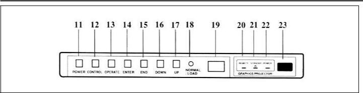
Control panel on the rear
11. POWER Button |
|
|
17. UP Button |
||
|
Turns the projector on or off when the projector is |
Used to increase the selected adjustment level or |
|||
|
in the standby condition (Main Power switch on |
move the cursor upward. When used with the |
|||
|
and Standby indicator lit). |
CONTROL button, the UP button works as the |
|||
12. CONTROL Button |
CURSOR > button on the remote control unit. |
||||
18. NORMAL/LOAD Button |
|||||
|
Used with other buttons. similar to a shift key on a |
||||
|
typewriter or computer. This is the same with the |
Returns the adjustment data to the standard level |
|||
|
CTL button on the remote control. |
(NORMAL function). |
|||
13. OPERATE Button |
Pressing this button with holding down the |
||||
CONTROL button returns the adjustment data to |
|||||
|
Press to display the OPERATE menu. You can |
the last stored level (LOAD function). |
|||
|
select the following adjustment functions from this |
|
|||
|
menu. |
|
|
19. Select Counter |
|
|
1/PICTURE |
4/INPUT SELECT |
Displays "00" in normal operation. |
||
|
2/POSITION |
5/SOURCE INFO |
|
||
|
3/SOUND |
6/STATIC |
20. REMOTE Indicator |
||
|
|
|
|
Flashes when the projector receives a signal from |
|
|
NOTE: The SOUND item is not included in the |
|
the remote control. |
||
|
“OPERATE” menu on the stand alone mode. |
|
21. STANDBY Indicator |
||
|
|
|
|
||
14. ENTER Button |
|
|
|||
|
|
Lights up when the projector's main POWER |
|||
|
Executes menu selection and switches to selected |
switch is on. Flashes when the projector might not |
|||
|
input. |
|
|
be connected with the Switcher correctly or when |
|
15. END Button |
|
|
the Switcher might be turned off. |
||
|
|
22. POWER Indicator |
|||
|
Exits t adjustment mode. |
||||
|
|
|
|
Lights up when the projector is turned on. |
|
16. DOWN Button |
|
|
23. Remote Sensor |
||
|
Used to decrease the selected adjustment level or |
||||
|
move the cursor downward. When used with the |
Receives the signal from the supplied remote |
|||
|
CONTROL button, the DOWN button works as |
control when used in the wireless condition. |
|||
|
the CURSOR < button on the remote control unit. |
|
|||

PART NAMES AND FUNCTIONS
Remote control unit
User Remote Control
RC-6010
Full Function Remote Control
RC-6011
NOTE: The full function remote control is designed for setup adjustment. Use the user remote control for normal operation.

PART NAMES AND FUNCTIONS
1.POWER Buttons (ON/OFF)
Press the ON button to turn the projector on when the projector is in the standby condition. (STANDBY indicator lit). Press the OFF button to return the projector to the standby condition.
2.TEST Button
Press to display the”TEST PATTERN” menu from which you can select the preferred test pattern.
3.ADJUST Button
Press to display the “ADJUST” menu.
4.OPERATE Button
Press to display the “OPERATE” menu.
5.Backlight Switch
Turns the backlight on and off.
6.PIC FUNC Button
Press to display the picture adjustment screen.
NOTE: Some function items will not be used depending on the input video signal.
7.SOUND FUNC Button
Press to display the VOLUME adjustment screen. You can adjust the volume of the ISS-6010/ISS-6010G Switcher.
8.PICTURE (PIC) MUTE Button
Press to mute the picture. Press again to return the picture.
9.SOUND MUTE Button
Press to mute the sound. Press again to return the sound.
NOTE: This works only with the ISS-6010/ISS-6010G.
10.DISPLAY Button
Press to turn on or off the ON-SCREEN display.
11.FOCUS Button
Press to enter the FOCUS mode.
12.STATIC Button
Press to enter the STATIC mode. You can adjust the static convergence.
13.POINT Button (when the point convergence board installed)
Press to enter the POINT mode. You can adjust the point convergence.
14.TILT SKEW ALIGN Button
Press to enter the TILTSKEW ALIGNMENT mode. You can adjust the tilt and the skew of the projected image.
15.TILT SKEW CONV Button
Press to enter the TILTSKEW CONVERGENCE mode. You can adjust the tilt and the skew convergence for the red or blue CRT.
16.BOW ALIGN Button
Press to enter the BOW ALIGNMENT mode. You can adjust the horizontal and the vertical bow of the projected image.
17.BOW CONV Button
Press to enter the BOW CONVERGENCE mode. You can adjust the horizontal and the vertical bow convergence for the red or blue CRT.
18.AMPLITUDE ALIGN Button
Press to enter the AMPLITUDE ALIGNMENT mode. You can adjust the horizontal width and the vertical height of the projected image.
19.AMPLITUDE CONV Button
Press to enter the AMPLITUDE CONVERGENCE mode. You can adjust the horizontal and the vertical convergence amplitude for the red or blue CRT.
20.LINEARITY ALIGN Button
Press to enter the LINEARITY ALIGNMENT mode. You can adjust the horizontal and the vertical linearity of the projected image.

PART NAMES AND FUNCTIONS
21.LINEARITY CONV Button
Press to enter the LINEARITY CONVERGENCE mode. You can adjust the horizontal and the vertical linearity convergence for the red or blue CRT. Pressing with CTL button controls the LINEARBALANCE convergence.
22.KEY STONE ALIGN Button
Press to enter the KEY STONE ALIGNMENT mode. You can adjust the horizontal and the vertical keystone of the projected image. Pressing with CTL button controls the KEY-BALANCE alignment.
23.KEY STONE CONV Button
Press to enter the KEY-STONE CONVERGENCE mode. You can adjust the horizontal and the vertical key-stone convergence for the red or blue CRT. Pressing with CTL button controls the KEYBALANCE convergence.
24.PIN CUSHION ALIGN Button
Press to enter the PIN-CUSHION ALIGNMENT mode. You can adjust the horizontal and the vertical pin-cushion of the projected image. Pressing with CTL button controls the PIN-BALANCE alignment.
25.PIN CUSHION CONV Button
Press to enter the PIN-CUSHION CONVERGENCE mode. You can adjust the horizontal and the vertical pin-cushion convergence for the red or blue CRT.
Pressing with CTL button controls the PINBALANCE convergence.
26.INPUT Button
Selects menus and switches input signals.
27.HELP Button
Press to display the explanation of the current selected function and available functions.
28.INPUT LIST Button
Press to display the list of the recorded input signals.
29.INFO Button
Press to display the various parameters and settings of the currently displayed image.
30.KELVIN Button
Press to enter the WHITE BALANCE mode. You can adjust the white and the black level.
31.POSITION Button
Press to enter the position mode. You can adjust the horizontal and vertical position and horizontal and vertical blanking.
32.R, G and B Buttons
Turn each CRT beam on and off separately. When using with the CTL button, you can select the CRT to be adjusted during convergence and center focus adjustments. Note that the G button is only on the full function remote control.
33.CURSOR Buttons
Used for increasing and decreasing control levels, cursor movement and convergence adjustments.
34.NORMAL Button
Returns the adjustments level for each VIDEO or RGB input signal to the standard level. When pressed once, the confirmation message will be displayed. When “YES” is selected and ENTER is pressed, the data will be returned to the standard level. Pressing with CTL returns the adjustment data to the last stored level (LOAD function).
35.STORE Button
Memorizes the adjustments setting of each VIDEO or RGB input signal separately. When pressed once, the confirmation message “STORE?” will be displayed.
When selecting “YES” and ENTER is pressed, the data will be stored in memory.
36.END Button
Ends the adjustment mode.
37.ENTER Button
Executes menu selection and switches to selected input.
38.CTL Button
Used with other buttons, similar to a shift key on a typewriter or computer.
39.Remote Control Jack
Insert the plug of the supplied remote cable here when the full function remote control is used in the wired condition.
PART NAMES AND FUNCTIONS
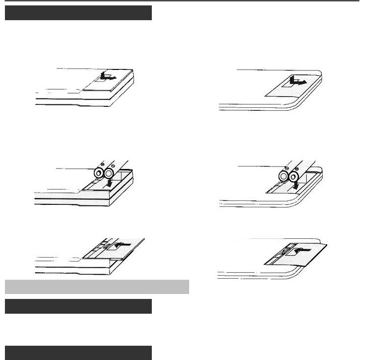
Battery installation and replacement
User remote control |
Full function remote control |
1.Press down on the battery compartment cover and slide the cover in the direction of the arrow.
2.Install the two new batteries, making sure that their polarity matches the (+) (-) diagrams inside the battery compartment.
3. Close the battery compartment cover.
1.Press down on the battery compartment cover and slide the cover in the direction of the arrow.
2.Install the two new batteries, making sure that their polarity matches the (+) (-) diagrams inside the battery compartment.
3. Close the battery compartment cover.
NOTE: The remote control is powered by two 1.5V AA batteries.
Remote control cautions
Use the remote control within the valid operating range within a distance of about 7m (23 ft.) and at 30 degrees angle left and right.
Handling remote control and batteries
•Do not drop or mishandle the remote.
•Do not get the remote wet. If the remote gets wet, wipe it dry immediately.
•Avoid heat and humidity.
•When not using the remote for a long period, remove the batteries.
•Do not use new and old batteries together, or use different types together.
•Do not take apart the batteries, heat them, or throw them into a fire.
•Avoid using the full function remote control as wireless with the backlight switch ON for an extended period of time. This can cause short battery life.
 Loading...