


For USA
Projector
PA1004UL-W/PA1004UL-B
PA804UL-W/PA804UL-B
User’s Manual
Please visit our web site for User’s Manual in the latest version:
https://www.nec-display.com/dl/en/pj_manual/lineup.html
Model No.
NP-PA1004UL-W/NP-PA1004UL-B/NP-PA804UL-W/NP-PA804UL-B

Ver. 1 2/20
• Apple, Mac, Mac OS, and MacBook are trademarks of Apple Inc. registered in the U.S. and other countries.
• Microsoft, Windows, Windows Vista, Internet Explorer, .NET Framework and PowerPoint are either a registered
trademark or trademark of Microsoft Corporation in the United States and/or other countries.
• MicroSaver is a registered trademark of Kensington Computer Products Group, a division of ACCO Brands.
• AccuBlend, NaViSet, and Virtual Remote are trademarks or registered trademarks of NEC Display Solutions, Ltd.
in Japan, in the United State and other countries.
• The terms HDMI and HDMI High-Denition Multimedia Interface, and the HDMI Logo are trademarks or registered
trademarks of HDMI Licensing Administrator, Inc. in the United States and other countries.
• DisplayPort and DisplayPort Compliance Logo are trademarks owned by the Video Electronics Standards Association.
• HDBaseT™ is a trademark of HDBaseT Alliance.
• Trademark PJLink is a trademark applied for trademark rights in Japan, the United States of America and other
countries and areas.
• Blu-ray is a trademark of Blu-ray Disc Association.
• CRESTRON and CRESTRON ROOMVIEW are trademarks or registered trademarks of Crestron Electronics, Inc.
in the United States and other countries.
• Extron and XTP are registered trademarks of RGB Systems, Inc. in the United States.
• Ethernet is either a registered trademark or trademark of Fuji Xerox Co., Ltd.
• Other product and company names mentioned in this user’s manual may be the trademarks or registered trademarks
of their respective holders.
• Virtual Remote Tool uses WinI2C/DDC library, © Nicomsoft Ltd.
NOTES
(1) The contents of this user’s manual may not be reprinted in part or whole without permission.
(2) The contents of this user’s manual are subject to change without notice.
(3) Great care has been taken in the preparation of this user’s manual; however, should you notice any questionable
points, errors or omissions, please contact us.
(4) Notwithstanding article (3), NEC will not be responsible for any claims on loss of prot or other matters deemed
to result from using the Projector.
Important Information
Please use the power cord supplied with this projector.
Safety Cautions
Precautions
Please read this manual carefully before using your NEC projector and keep the manual handy for future reference.
CAUTION
To turn off main power, be sure to remove the plug from power outlet.
The power outlet socket should be installed as near to the equipment as possible, and should be easily
accessible.
CAUTION
TO PREVENT SHOCK, DO NOT OPEN THE CABINET.
THERE ARE HIGH-VOLTAGE COMPONENTS INSIDE.
REFER SERVICING TO QUALIFIED SERVICE PERSONNEL.
This symbol warns the user that uninsulated voltage within the unit may be sufficient to cause electrical
shock. Therefore, it is dangerous to make any kind of contact with any part inside of the unit.
This symbol alerts the user that important information concerning the operation and maintenance of this
unit has been provided.
The information should be read carefully to avoid problems.
WARNING: TO PREVENT FIRE OR SHOCK, DO NOT EXPOSE THIS UNIT TO RAIN OR MOISTURE.
DO NOT USE THIS UNIT’S PLUG WITH AN EXTENSION CORD OR IN AN OUTLET UNLESS ALL THE PRONGS
CAN BE FULLY INSERTED.
CAUTION
Avoid displaying stationary images for a prolonged period of time.
Doing so can result in these images being temporarily sustained on the surface of the LCD panel.
If this should happen, continue to use your projector. The static background from previous images will
disappear.
i
Important Information
Disposing of your used product
If you wish to dispose of used electrical and electronic products, please contact your local authority and ask for the
correct method of disposal.
Important Safeguards
These safety instructions are to ensure the long life of your projector and to prevent re and shock. Please read them
carefully and heed all warnings.
Installation
• Do not place the projector in the following conditions:
- on an unstable cart, stand, or table.
- near water, baths, or damp rooms.
- in direct sunlight, near heaters, or heat radiating appliances.
- in a dusty, smoky or steamy environment.
- on a sheet of paper or cloth, rugs or carpets.
• Do not install and store the projector in the below circumstances. Failure to do so may cause of malfunction.
- In powerful magnetic elds
- In corrosive gas environment
- Outdoors
• When installing the projector at an angle, the separately sold option cover may be required for safety depending on
the installation angle of the projector. (→ page 00)
WARNING
• Do not cover the lens with the lens cap or equivalent while the projector is on. Doing so can lead to melting of
the cap due to the heat emitted from the light output.
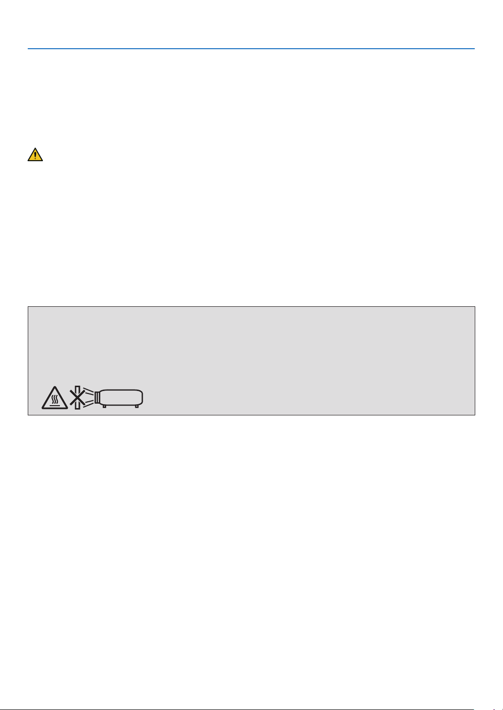
• Do not place any objects, which are easily affected by heat, in front of the projector lens. Doing so could lead to
the object melting from the heat that is emitted from the light output.
The below pictogram indicated on the cabinet means the precaution for avoiding to place objects in front of the
projector lens.
ii
Important Information
Safety Precaution on Ceiling Installation
WARNING
• Consult your dealer for installing the projector on the ceiling. Special skills are required for ceiling installation.
• DO NOT perform installation work by people other than installers. Doing so may result in the projector falling and
causing injury.
• We are not liable for any accident or/and damage resulting from improper installation or handling, misuse, modication, or natural disasters.
Do not install the projector in the following places. Attached substances such as oil, chemicals and moisture may
cause deformation or cracks of the cabinet, corrosion of the metal parts, or malfunction.
• Outdoors and places with humid or dust
• Places exposed to oil smoke or steam
• Places where corrosive gases are generated
To the dealer and the installer
1. To prevent the projector from falling, install it on the ceiling in a way with sufficient strength to withstand the combined
weight of the projector and the ceiling mount unit for an extended period of time.
2. When installing the projector on the ceiling, be sure to do so correctly in accordance with the installation manual for
the Ceiling Mount Unit. Be sure to use the xed metal ttings and to tighten the screws securely.
3. To prevent the projector from falling, use fall prevention wires.
• Use commercially available metal ttings to join the robust part of a building or construction and the security bar
of the projector with the fall prevention wires.
• Use commercially available metal ttings and fall prevention wires that have sufficient strength to withstand the
combined weight of the projector and the ceiling mount unit.
• Slightly slack off the fall prevention wires so as not to put a load on the projector.
• Refer to the user manual supplied with the projector for the location of the security bar. (→ page 6)
Fire and Shock Precautions
• Ensure that there is sufficient ventilation and that vents are unobstructed to prevent the build-up of heat inside your
projector. Allow enough space between your projector and a wall. (→ page xi)
• Prevent foreign objects such as paper clips and bits of paper from falling into your projector. Do not attempt to retrieve
any objects that might fall into your projector. Do not insert any metal objects such as a wire or screwdriver into your
projector. If something should fall into your projector, disconnect it immediately and have the object removed by a
qualied service personnel.
• Do not place any objects on top of the projector.
• Do not touch the power plug during a thunderstorm. Doing so may cause electrical shock.
• The projector is designed to operate on a power supply of 100-240V AC 50/60 Hz. Ensure that your power supply
ts this requirement before attempting to use your projector.
• Make sure to mount the power cord stopper before attempting to use your projector. Please refer to page 15 about
the power cord stopper.
• Do not look into the light source using optical instruments (such as magnifying glasses and mirrors). Visual impairment could result.
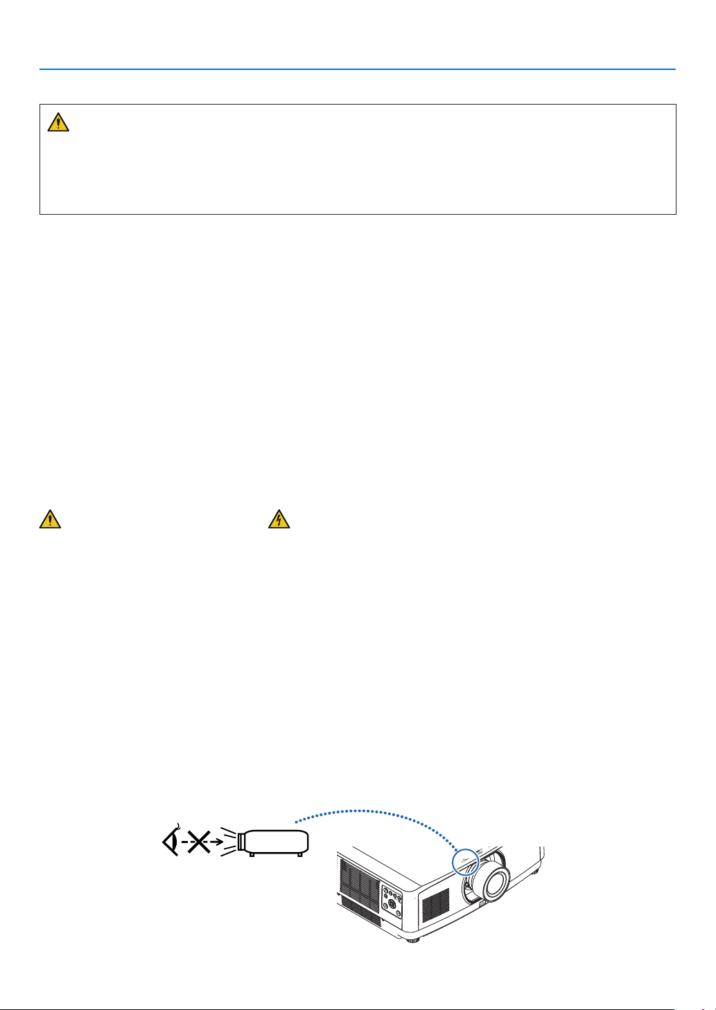
• When turning on the projector, ensure that nobody is facing towards the lens in the path of the light emitted from the
laser. Do not look into the lens while the projector is on. Serious damage to your eyes could result. The following
graphic symbol indicating that looking into the projector is prohibited is displayed on top of the projector above the
lens mounting unit.
iii

Important Information
• Perform the adjustment from behind or from the side of the projector. Adjusting from the front could expose your
eyes to strong light which could injure them.
• Keep any items (magnifying glass etc.) out of the light path of the projector. The light path being projected from the
lens is extensive, therefore any kind of abnormal objects that can redirect light coming out of the lens, can cause
an unpredictable outcome such as a re or injury to the eyes.
• Do not place any objects, which are easily affected by heat, in front of a projector exhaust vent.
Doing so could lead to the object melting or getting your hands burned from the heat that is emitted from the exhaust
vent.
• Handle the power cord carefully. A damaged or frayed power cord can cause electric shock or re.
- Do not bend or tug the power cord excessively.
- Do not place the power cord under the projector, or any heavy object.
- Do not cover the power cord with other soft materials such as rugs.
- Do not heat the power cord.
- Do not handle the power plug with wet hands.
• Turn off the projector, unplug the power cord and have the projector serviced by a qualied service personnel under
the following conditions:
- When the power cord or plug is damaged or frayed.
- If liquid has been spilled into the projector, or if it has been exposed to rain or water.
- If the projector does not operate normally when you follow the instructions described in this user’s manual.
- If the projector has been dropped or the cabinet has been damaged.
- If the projector exhibits a distinct change in performance, indicating a need for service.
• Disconnect the power cord and any other cables before carrying the projector.
• Turn off the projector and unplug the power cord before cleaning the cabinet or cleaning or replacing the lens.
• Turn off the projector and unplug the power cord if the projector is not to be used for an extended period of time.
• When using a LAN cable:
For safety, do not connect to the connector for peripheral device wiring that might have excessive voltage.
• Do not use the malfunctioned projector. It may cause not only re or electric shock but also serious damage to your
eyesight or burns.
• Do not let children to operate the projector by themselves. If the projector is operated by children, adults need to
attend and keep their eyes on children.
• If damage or malfunction of the projector is found, immediately stop to use it and consult your dealer for repair.
• Never disassemble, repair, and remodel by end users. If these are performed by end users, it may cause re, electric
shock, or laser light leakage, resulting in serious damage to your eyesight or burns.
• Consult your dealer for disposing the projector. Never disassemble the projector before disposing it.
CAUTION
• Do not use the tilt-foot for purposes other than originally intended. Misuses such as gripping the tilt-foot or hanging on the wall can cause damage to the projector.
• Do not hold the option cover while moving the projector or do not apply excessive force to the option cover. Doing
so may damage the option cover, resulting in injury.
• Be sure to tighten the screws after attaching the option cover. Failure to do so may cause the option cover to
come off and fall, resulting in injury or damage to the option cover.
• Do not put bundled cables in the option cover. Doing so may damage the power cord, resulting in a re.
• Select [HIGH] in Fan mode if you continue to use the projector for consecutive days. (From the menu, select
[SETUP] → [OPTIONS(1)] → [FAN MODE] → [MODE] → [HIGH].)
• Do not unplug the power cable from the wall outlet or projector when the projector is powered on. Doing so can
cause damage to the AC IN terminal of the projector and (or) the prong plug of the power cable.
To turn off the AC power supply under the state the projector is ON, use a power strip equipped with a switch
and a breaker.
• A minimum of two persons are required to carry the projector. Otherwise the projector may tumble or drop, causing personal injury.
• If intense light like laser beams enters from the lens, it could lead to malfunction.
iv

Important Information
Caution on Handling the Optional Lens
• When shipping the projector with the lens, remove the lens before shipping the projector. Always attach the dust
cap to the lens whenever it is not mounted on the projector. The lens and the lens shift mechanism may encounter
damage caused by improper handling during transportation.
• Do not hold the lens part when carrying the projector.
Doing so could cause the focus ring to rotate, resulting in accidental dropping of the projector.
• In the condition the projector is no lens mounted, do not put your hands in the lens mount opening for carrying the
projector.
• For mounting, replacing, and cleaning the lens, make sure to power off the projector and disconnect the power cord.
Failure to do so can result in eye injury, electric shock, or burn injuries.
• Keep hands away from the lens mounting portion while performing a lens shift. Failure to do so could result in ngers
being pinched by the moving lens.
Cable information
Use shielded cables or cables attached ferrite cores so as not to interfere with radio and television reception.
For details, please refer to “6. Connecting to Other Equipment” in this user’s manual.
Remote Control Precautions
• Handle the remote control carefully.
• If the remote control gets wet, wipe it dry immediately.
• Avoid excessive heat and humidity.
• Do not short, heat, or take apart batteries.
• Do not throw batteries into re.
• If you will not be using the remote control for a long time, remove the batteries.
• Ensure that you have the batteries’ polarity (+/−) aligned correctly.
• Do not use new and old batteries together, or use different types of batteries together.
• Dispose of used batteries according to your local regulations.
v

Important Information
About High Altitude mode
• Set [FAN MODE] to [HIGH ALTITUDE] when using the projector at altitudes approximately 5500 feet/1700 meters
or higher.
Using the projector at altitudes approximately 5500 feet/1700 meters or higher without setting to [HIGH ALTITUDE]
can cause the projector to overheat and the protector could shut down. If this happens, wait a couple minutes and
turn on the projector.
• Using the projector at altitudes less than approximately 5500 feet/1700 meters and setting to [HIGH ALTITUDE]
can cause the light module to overcool, causing the image to icker. Switch [FAN MODE] to [AUTO].
• Using the projector at altitudes approximately 5500 feet/1700 meters or higher can shorten the life of optical components such as the light module.
Light Module
1. A light module containing multiple laser diodes is equipped in the product as the light source.
2. These laser diodes are sealed in the light module. No maintenance or service is required for the performance of
the light module.
3. End user is not allowed to replace the light module.
4. Contact qualied distributor for light module replacement and further information.
Laser Safety Caution
• For USA
This product is classied as Class 3R of IEC 60825-1 Second edition 2007-03
Complies with FDA performance standards for laser products except for deviations pursuant to Laser Notice No.
50, dated June 24, 2007.
For other regions
This product is classied as Class 1 of IEC 60825-1 Third edition 2014-05 and RG3 of IEC/EN 62471-5 First edition
2015-06.
Obey the laws and regulations of your country in relation to the installation and management of the device.
• Outline of laser emitted from the built-in light module:
• Wave length: 455 nm
• Maximum power: 257 W (PA1004UL-W/PA1004UL-B), 229 W (PA804UL-W/PA804UL-B)
• Radiation pattern from the protective housing:
• Wave length: 455 nm
• Maximum laser radiation output: 333 mW
• The laser module is equipped in this product. Use of controls or adjustments of procedures other than those specied herein may result in hazardous radiation exposure.
WARNING – CLASS 3R OF IEC 60825-1 SECOND EDITION LASER PRODUCT
LASER RADIATION – AVOID DIRECT EYE EXPOSURE
• Use of controls or adjustments or performance of procedures other than those specied herein may result in
hazardous radiation exposure.
vi
Laser light radiation range
HC
HC
HR
HL
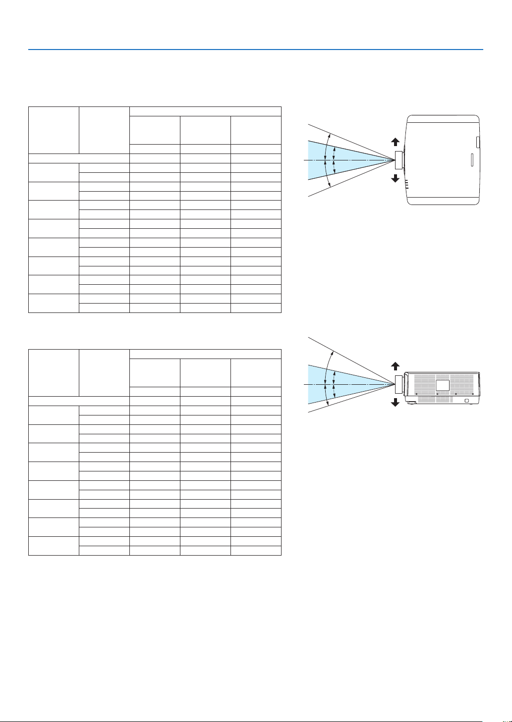
The gure below shows the maximum radiation range of the laser light.
Important Information
Horizontal angle (unit: degree)
Lens position
Lens unit Zoom
NP11FL 31.8 31.8 31.8
NP30ZL
NP12ZL
NP13ZL
NP14ZL
NP15ZL
NP40ZL
NP41ZL
NP43ZL
Tele 33.6 25.4 33.6
Wide 40.9 31.8 40.9
Tele 27.4 18.0 27.4
Wide 34.0 22.9 34.0
Tele 15.1 9.6 15.1
Wide 28.3 18.6 28.3
Tele 9.6 6.0 9.6
Wide 15.1 9.6 15.1
Tele 6.4 4.0 6.4
Wide 9.7 6.1 9.7
Tele 31.7 23.8 31.7
Wide 41.0 31.8 41.0
Tele 13.0 9.4 13.0
Wide 27.9 20.7 27.9
Tele 6.8 4.9 6.8
Wide 13.4 9.7 13.4
Left most
HR HC HL
Center
(Reference
value)
Right most
Vertical angle (unit: degree)
Lens position
Lens unit Zoom
NP11FL 21.2 21.2 21.2
NP30ZL
NP12ZL
NP13ZL
NP14ZL
NP15ZL
NP40ZL
NP41ZL
NP43ZL
Tele 30.7 16.5 19.6
Wide 37.7 21.1 24.9
Tele 24.0 11.5 13.7
Wide 30.1 14.8 17.6
Tele 13.0 6.0 7.2
Wide 24.8 11.9 14.1
Tele 8.3 3.8 4.5
Wide 13.1 6.0 7.2
Tele 5.5 2.5 3.0
Wide 8.4 3.8 4.6
Tele 28.9 15.4 18.3
Wide 37.8 21.2 24.9
Tele 11.6 5.9 7.0
Wide 25.3 13.3 15.8
Tele 6.1 3.0 3.7
Wide 12.0 6.1 7.3
Upper most
VU VC VD
Center
(Reference
value)
Lower most
HR
HL
VU
VD
Right
HC
HC
Left
Upper
VC
VC
Lower
vii
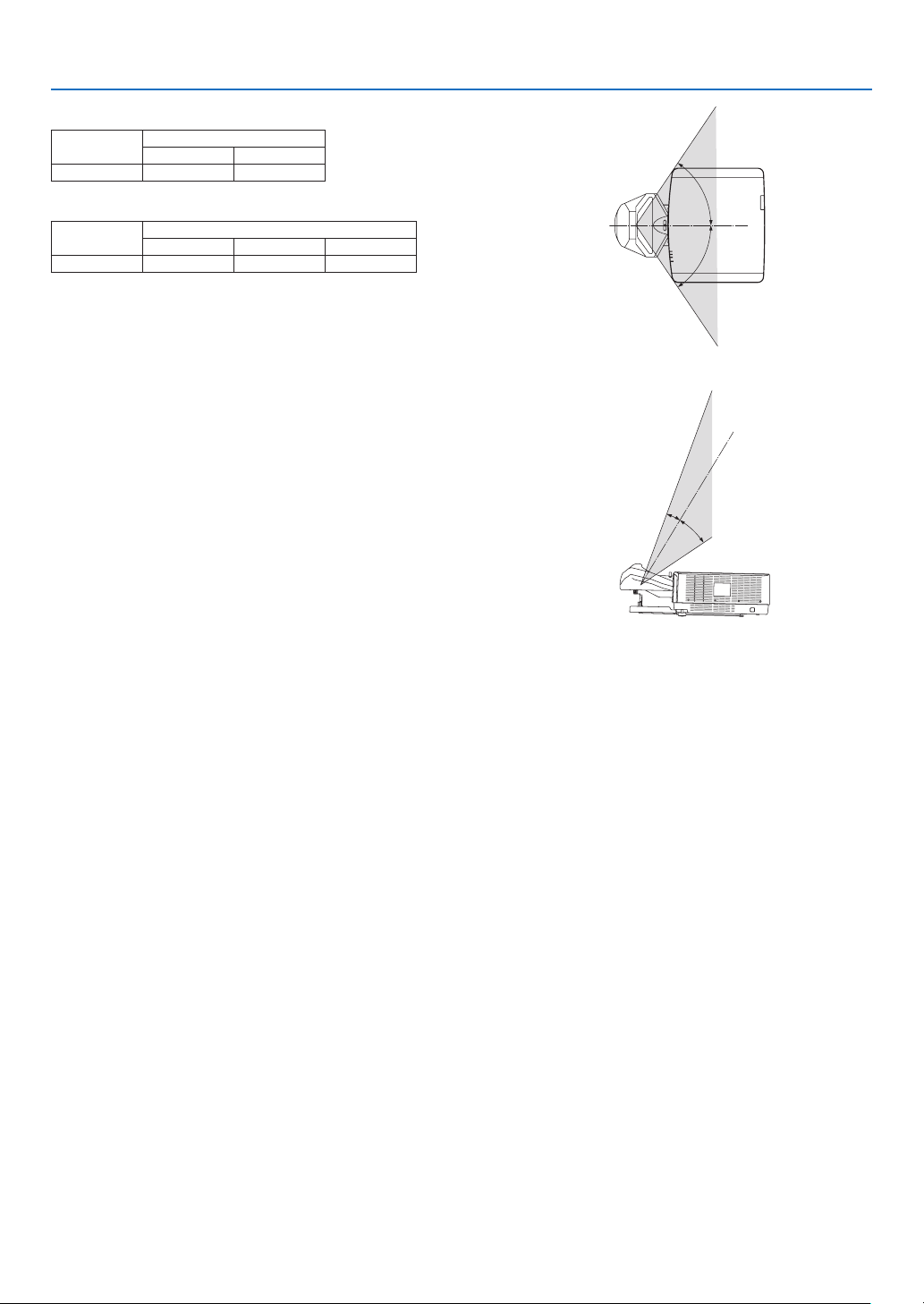
Horizontal angle (unit: degree)
Lens unit
NP44ML - 55.8
Zoom
Tele Wide
Vertical angle (unit: degree)
Lens unit
Tele V1 V2
NP44ML - 10.7 24.6
Zoom
Important Information
H
H
1
V
2
V
viii
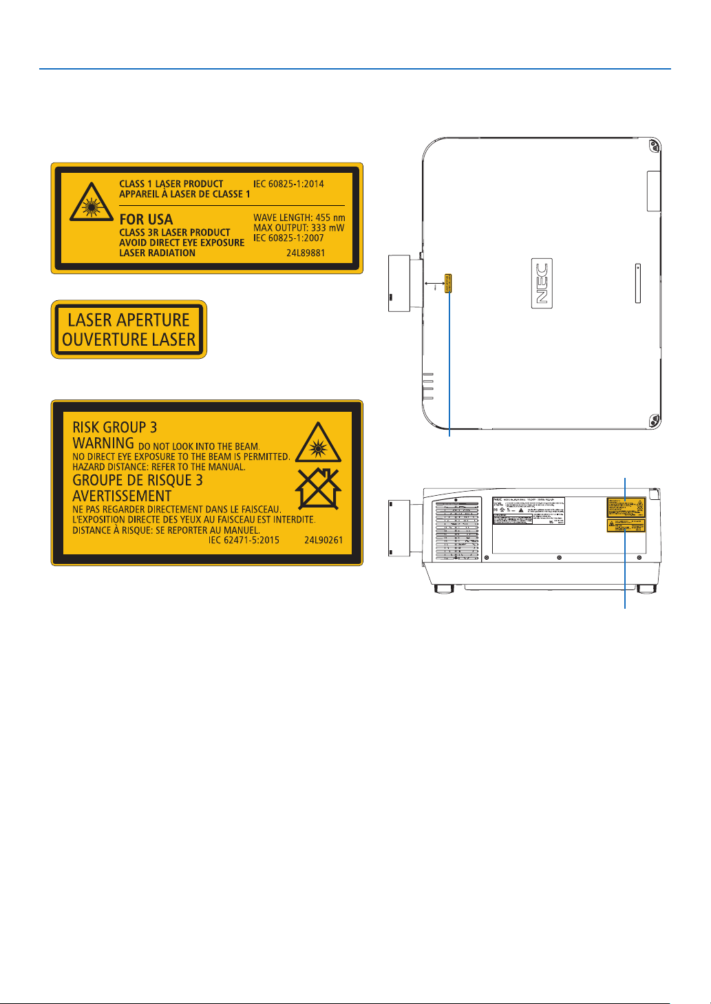
Label Information
• The caution and the explanatory labels are stuck on the below indicated positions.
For USA
Label 1
Label 2
For other regions
Label 3
Label 2
Important Information
Label 3
ix
Label 1

Important Information
FCC Information
WARNING
• The Federal Communications Commission does not allow any modications or changes to the unit EXCEPT
those specied by NEC Display Solutions of America, Inc. in this manual. Failure to comply with this government
regulation could void your right to operate this equipment.
• This equipment has been tested and found to comply with the limits for a class A digital device, pursuant to Part
15 of the FCC Rules. These limits are designed to provide reasonable protection against harmful interference
when the equipment is operated in a commercial environment. This equipment generates, uses, and can radiate radio frequency energy and, if not installed and used in accordance with the instruction manual, may cause
harmful interference to radio communications. Operation of this equipment in a residential area is likely to cause
harmful interference in which case the user will be required to correct the interference at his own expense.
Supplier’s declaration of conformity (for USA only)
This device complies with Part 15 of FCC Rules. Operation is subject to the following two conditions.
(1) This device may not cause harmful interference, and (2) this device must accept any interference received,
including interference that may cause undesired operation.
U.S.Responsible Party: NEC Display Solutions of America, Inc.
Address: 3250 Lacey Rd, Ste 500
Downers Grove, IL 60515
Telephone Number: 630-467-3000
Type of Product: Projector
Equipment Classication: Class A Peripheral
Model Number: NP-PA1004UL-W/NP-PA1004UL-B/
NP-PA804UL-W/NP-PA804UL-B
x

Important Information
About Copyright of original projected pictures:
Please note that using this projector for the purpose of commercial gain or the attraction of public attention in a venue
such as a coffee shop or hotel and employing compression or expansion of the screen image with the following functions may raise concern about the infringement of copyrights which are protected by copyright law.
[ASPECT RATIO], [KEYSTONE], Magnifying feature and other similar features.
Health precautions to users viewing 3D images
Before viewing, be sure to read health care precautions that may be found in the user’s manual included with your 3D
eyeglasses or your 3D compatible content such as Blu-ray Discs, video games, computer’s video les and the like.
To avoid any adverse symptoms, heed the following:
• Do not use 3D eyeglasses for viewing any material other than 3D images.
• Allow a distance of 2 m/7 feet or greater between the screen and a user. Viewing 3D images from too close a
distance can strain your eyes.
• Avoid viewing 3D images for a prolonged period of time. Take a break of 15 minutes or longer after every hour
of viewing.
• If you or any member of your family has a history of light-sensitive seizures, consult a doctor before viewing 3D
images.
• While viewing 3D images, if you get sick such as nausea, dizziness, queasiness, headache, eyestrain, blurry
vision, convulsions, and numbness, stop viewing them. If symptoms still persist, consult a doctor.
• View 3D images from the front of the screen. Viewing from an angle may cause fatigue or eyestrain.
AUTO POWER OFF Function
The factory default setting for [AUTO POWER OFF] is 15 minutes. If no input signal is received and no operation is
performed on the projector during 15 minutes, the projector is automatically powered off for saving the power consumption. In order to control the projector by an external device, set the [AUTO POWER OFF] to [OFF]. Please refer
page 131 for details.
Information of the AUDIO OUT mini jack
The AUDIO OUT mini jack does not support earphone/headphone terminal.
xi
Important Information
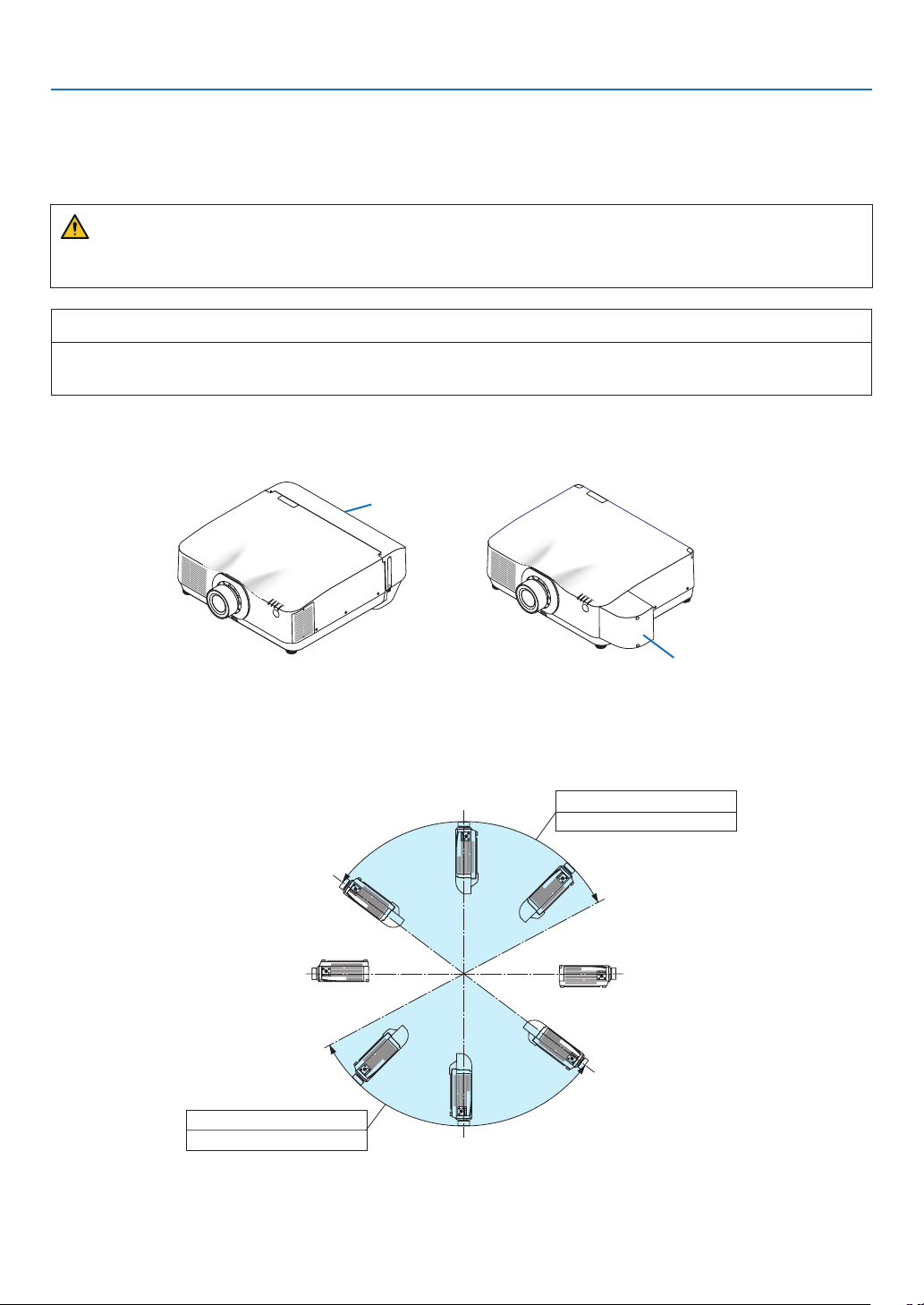
90º
270º
Precautions when installing the projector at an angle
This projector can be installed universally in every angle. When installing the projector at the angles shown below,
use the separately sold option cover. Be sure to ask your dealer to attach the option cover.
WARNING
• For safety reasons, be sure to attach the option cover.
• Be sure to attach the option cover to the projector when the projector’s power is turned on.
Model name of option cover
NP13CV-W for PA1004UL-W/PA804UL-W
NP13CV-B for PA1004UL-B/PA804UL-B
Two covers are packaged with the option cover NP13CV-W and NP13CV-B.
• Option cover A: for attaching to the connection port area
• Option cover B: for attaching to the exhaust vent
option cover A
option cover B
The drawings below show the installation angle required to attach the option cover A and B respectively. Both option
cover A and B may need to be attached depending on the installation position of the projector.
Installation angles required to attach the option cover A
In the direction of back and forth
28º - 143º
Option cover A must be attached
0º180º
208º - 323º
Option cover A must be attached
xii
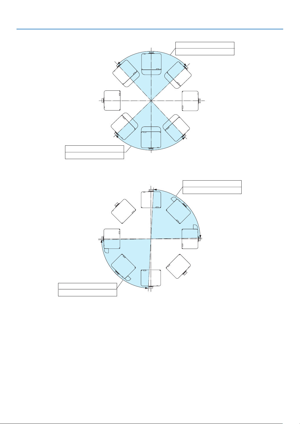
In the direction of left and right
270º
90º
270º
90º
224º - 313º
Option cover A must be attached
Installation angles required to attach the option cover B
Important Information
44º - 133º
Option cover A must be attached
0º180º
1º - 87º
Option cover B must be attached
181º - 267º
Option cover B must be attached
0º180º
xiii
Important Information
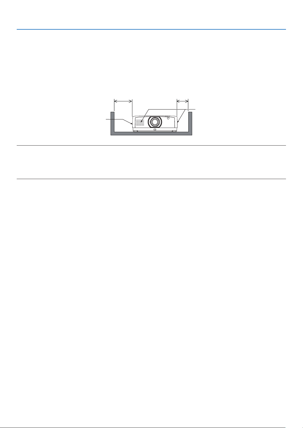
Clearance for Installing the Projector
Allow ample clearance between the projector and its surroundings as shown below. The high temperature exhaust
coming out of the device may be sucked into the device again. Required clearance is same whenever the projector
is installed in any angle.
Avoid installing the projector in a place where air movement from the HVAC is directed at the projector.
Heated air from the HVAC can be taken in by the projector’s intake vent. If this happens, the temperature inside the
projector will rise too high causing the over-temperature protector to automatically turn off the projectors power.
20 cm/7.9" or greater 13 cm/5.1" or greater
Intake vent
Exhaust vent
NOTE:
• The drawing shows the proper clearance required for the left and right of the projector assuming sufficient clearance has been
kept for the front, back and top of the projector.
• For the portrait projection, each required clearance between the floor and the intake or the exhaust vent is same with the clearance
on the upper illustration. See page 148 for an installation example on portrait projection.
xiv

Table of Contents
Important Information ............................................................................................ i
1. Introduction ...........................................................................................................1
❶ What’s in the Box? ..........................................................................................................1
❷ Introduction to the Projector ............................................................................................2
General .....................................................................................................................2
Light source · Brightness ..........................................................................................2
Installation .................................................................................................................2
Videos .......................................................................................................................2
Network .....................................................................................................................3
Energy-saving ...........................................................................................................3
About this user’s manual ...........................................................................................4
❸ Part Names of the Projector ...........................................................................................5
Front/Top ................................................................................................................... 5
Rear ..........................................................................................................................6
Controls/Indicator Panel ............................................................................................7
Terminals ..................................................................................................................8
❹ Part Names of the Remote Control ................................................................................. 9
Battery Installation ..................................................................................................10
Remote Control Precautions ...................................................................................10
Operating Range for Wireless Remote Control ....................................................... 11
2. Projecting an Image (Basic Operation) ...............................................12
❶ Flow of Projecting an Image .........................................................................................12
❷ Connecting Your Computer/Connecting the Power Cord ..............................................13
Using the power cord stopper .................................................................................14
❸ Turning on the Projector ................................................................................................15
Performing Lens Calibration ................................................................................... 15
Note on Startup screen (Menu Language Select screen) .......................................16
❹ Selecting a Source .......................................................................................................17
❺ Adjusting the Picture Size and Position ........................................................................19
Adjusting the vertical position of a projected image (Lens shift) .............................20
Focus ......................................................................................................................21
Zoom .......................................................................................................................24
Adjusting the Tilt Foot ..............................................................................................25
❻ Optimizing Computer Signal Automatically ...................................................................26
❼ Turning Up or Down Volume .........................................................................................26
❽ Turning off the Projector
❾ After Use .......................................................................................................................28
................................................................................................27
xv

Table of Contents
3. Convenient Features ......................................................................................29
❶ Turn off the light of the projector (LENS SHUTTER) .....................................................29
❷ Turning off the Image and Sound .................................................................................. 29
❸ Shift the On-Screen Menu displaying position ..............................................................30
❹ Freezing a Picture .........................................................................................................31
❺ Enlarging a Picture .......................................................................................................31
❻ Changing LIGHT MODE/Checking Energy-Saving Effect Using LIGHT MODE
[LIGHT MODE]........................................................................................................32
Checking Energy-Saving Effect [CARBON METER] ...............................................34
❼ Correcting Horizontal and Vertical Keystone Distortion [CORNERSTONE] ..................35
❽ Operation for the On-Screen Menu by a commercially available USB mouse ..............37
Menu operation .......................................................................................................37
Menu position control ..............................................................................................38
Geometric correction ...............................................................................................38
❾
Preventing the Unauthorized Use of the Projector [SECURITY] ........................................40
❿ Projecting 3D videos ..................................................................................................... 43
Procedure to watch 3D videos using this projector .................................................43
When videos cannot be viewed in 3D .....................................................................45
⓫ Controlling the Projector by Using an HTTP Browser ...................................................46
⓬ Storing Changes for Lens Shift, Zoom, and Focus [LENS MEMORY]..........................53
To store your adjusted values in [REF. LENS MEMORY]: .......................................54
To call up your adjusted values from [REF. LENS MEMORY]: ................................56
4. Multi-Screen Projection ...............................................................................59
❶ Things that can be done using multi-screen projection ................................................59
Case 1. Using a single projector to project two types of videos [PIP/PICTURE
BY PICTURE]..........................................................................................................59
Case 2. Using four projectors to project videos with a resolution of 3840 ×
2160 pixels [TILING] ...............................................................................................60
Things to note when installing projectors ................................................................62
❷ Displaying Two Pictures at the Same Time ...................................................................63
Projecting two screens ............................................................................................ 64
Switching the main display with the sub-display and vice versa .............................65
Restrictions .............................................................................................................66
❸ Displaying a Picture Using [EDGE BLENDING] ...........................................................67
Setting the overlap of projection screens ................................................................68
[BLEND CURVE].....................................................................................................70
Black Level Adjustment ...........................................................................................71
xvi

Table of Contents
5. Using On-Screen Menu .................................................................................73
❶ Using the Menus ...........................................................................................................73
❷ Menu Elements ............................................................................................................. 74
❸ List of Menu Items ........................................................................................................75
❹ Menu Descriptions & Functions [INPUT] ......................................................................81
❺ Menu Descriptions & Functions [ADJUST] ...................................................................85
[PICTURE] ..............................................................................................................85
[IMAGE OPTIONS] .................................................................................................89
[VIDEO] ...................................................................................................................93
[3D SETTINGS] ......................................................................................................95
Using the Lens Memory Function [LENS MEMORY] .............................................. 96
❻ Menu Descriptions & Functions [DISPLAY] .................................................................. 98
[PIP/PICTURE BY PICTURE] .................................................................................98
[GEOMETRIC CORRECTION] ............................................................................. 100
[EDGE BLENDING] ..............................................................................................105
[MULTI SCREEN]..................................................................................................106
❼ Menu Descriptions & Functions [SETUP] ...................................................................108
[MENU(1)] ............................................................................................................. 108
[MENU(2)] ............................................................................................................. 109
[INSTALLATION(1)] ............................................................................................... 110
[INSTALLATION(2)] ............................................................................................... 11 4
[CONTROL] .......................................................................................................... 115
[NETWORK SETTINGS] ....................................................................................... 122
[SOURCE OPTIONS] ...........................................................................................127
[POWER OPTIONS] .............................................................................................129
Returning to Factory Default [RESET] ..................................................................131
❽ Menu Descriptions & Functions [INFO.] .....................................................................132
[USAGE TIME] ......................................................................................................132
[SOURCE(1)] ........................................................................................................133
[SOURCE(2)] ........................................................................................................133
[SOURCE(3)] ........................................................................................................133
[SOURCE(4)] ........................................................................................................134
[WIRED LAN] ........................................................................................................ 134
[VERSION(1)] .......................................................................................................134
[OTHERS] .............................................................................................................135
[CONDITIONS] .....................................................................................................135
[HDBaseT] ............................................................................................................136
6. Connecting to Other Equipment ...........................................................137
❶ Making Connections ................................................................................................... 137
Analog RGB signal connection .............................................................................137
Digital RGB signal connection ..............................................................................138
Connecting Component Input ...............................................................................140
Connecting HDMI Input ......................................................................................... 141
Connecting to a HDBaseT transmission device (sold commercially) .................... 142
Connecting several projectors ...............................................................................143
Portrait projection (vertical orientation) .................................................................144
Connecting to a Wired LAN ................................................................................... 146
xvii

Table of Contents
7. Maintenance .....................................................................................................147
❶ Cleaning the Lens.......................................................................................................147
❷ Cleaning the Cabinet ..................................................................................................147
8. Appendix ..............................................................................................................148
❶ Throw distance and screen size .................................................................................148
Lens types and throw distance .............................................................................148
Tables of screen sizes and dimensions .................................................................149
Lens shifting range ................................................................................................149
❷ Compatible Input Signal List .......................................................................................151
❸ Specications .............................................................................................................154
❹ Cabinet Dimensions ...................................................................................................157
❺ Pin assignments and signal names of main connectors .............................................158
❻ Changing the Background Logo (Virtual Remote Tool) ............................................... 160
❼ Troubleshooting ..........................................................................................................161
Feature of each indicator ......................................................................................161
Indicator Message (Status message) ...................................................................161
Indicator Message (Error message) ......................................................................163
Common Problems & Solutions ............................................................................164
If there is no picture, or the picture is not displayed correctly. ...............................166
❽ PC Control Codes and Cable Connection ..................................................................167
ABOUT THE ASCII CONTROL COMMAND ......................................................... 168
❾ Attaching the separately sold options .........................................................................170
Mounting a lens (sold separately) .........................................................................170
Mounting the lens..................................................................................................170
Removing the lens ................................................................................................172
Attaching the option cover (separately sold) .........................................................173
❿ Troubleshooting Check List .........................................................................................175
⓫ REGISTER YOUR PROJECTOR! (for residents in the United States, Canada, and
Mexico) .................................................................................................................177
xviii
1. Introduction
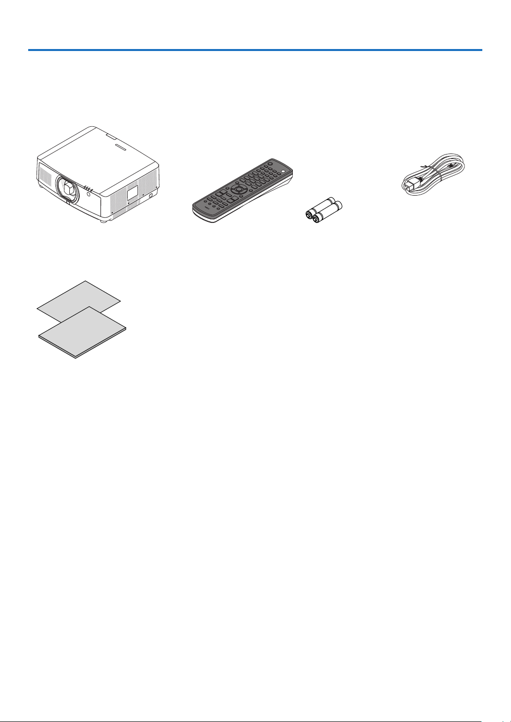
❶ What’s in the Box?
Make sure your box contains everything listed. If any pieces are missing, contact your dealer.
Please save the original box and packing materials if you ever need to ship your projector.
Projector
Dust cap for lens (24F54091)
* The projector is shipped without
a lens. For the types of lens and
throw distances, see page 152.
• Important Infomation
(7N8R0161)
• Quick Setup Guide (7N8R0171)
• Security Sticker
(Use this sticker when security
password is set on.)
• Limited warranty
Remote control
(7N901081)
Lens mask
AAA alkaline batteries
(x2)
Power cord
(7N080533)
1

1. Introduction
❷ Introduction to the Projector
This section introduces you to your new projector and describes the features and controls.
General
• Liquid crystal type high brightness/high resolution projector
Model Brightness Resolution Aspect Ratio
PA1004UL-W/PA1004UL-B NORMAL: 9000lm, BOOST: 10000lm WUXGA (1920 × 1200) 16:10
PA804UL-W/PA804UL-B NORMAL: 7500lm, BOOST: 8200lm WUXGA (1920 × 1200) 16:10
Light source · Brightness
• A long-life laser diode is equipped in the light module
The product can be operated at low cost because the laser light source can be used for a long time without requir-
ing replacement or maintenance.
• Brightness can be adjusted within a wide range
Unlike with ordinary light sources, the brightness can be adjusted from 30 to 100% in 1% increments.
• [CONSTANT BRIGHTNESS] mode
Brightness normally decreases with use, but by selecting [CONSTANT BRIGHTNESS] mode, sensors inside the
projector detect and automatically adjust the output, thereby maintaining constant brightness throughout the life
of the light module.
However, if brightness output is set at the maximum, brightness will decrease with use.
Installation
• Wide range of optional lenses selectable according to the place of installation
This projector supports 10 types of optional lenses, providing a selection of lenses adapted to a variety of places
of installation and projection methods.
In addition, the lenses can be mounted and removed in one touch.
Note that no lens is mounted upon shipment from the factory. Please purchase optional lenses separately.
• 360 dgeree free projection
This projector can be installed universally in every angle
The separately sold option cover is required to be attached to the projector depending on the installation angle of
the projector.
For controlling ne inclination, use the tilt foot. Install an appropriate metal and a stand that has enough strength
to support the projector for controlling the installation angle.
Videos
• Wide range of input/output terminals (HDMI, DisplayPort, HDBaseT, etc.)
The projector is equipped with a variety of input/output terminals: HDMI (input × 2), DisplayPort, HDBaseT (input
x 1, output x 1), computer (analog), etc.
The projector’s HDMI input, DisplayPort input terminals and HDBaseT Ports support HDCP.
• HDMI and HDBaseT support HDCP 2.2/1.4
• DisplayPort supports HDCP 1.3
• Simultaneous display of 2 images (PIP/PICTURE BY PICTURE)
Two images can be projected simultaneously with a single projector.
There are two types of layouts for the two images: “picture-in-picture” in which a sub-picture is displayed on the
main picture, and “picture-by-picture” in which the main and sub pictures are displayed next to each other.
2

1. Introduction
• Multi-screen projection using multiple projectors
This projetor equips the HDBaseT IN/Ethernet and HDBaseT OUT/Ethernet ports. Multiple projectors in same
brightness up to four units can be conneted in a daisy chain by a LAN*1 cable via these terminals. A high quality
picture is achieved by dividing and projecting high resolution videos among the various projectors.
Furthermore, the boundaries of the screens are smoothed using an edge blending function.
*1 Use a commercially available CAT 5e STP cable or one in a higher specication.
• Seamless switch function for smoother screen changes when switching the signal
When the input connector is switched, the image displayed before switching is held so that that the new image can
be switched to without a break due to absence of a signal.
• Supports HDMI 3D format
This projector can be used to watch videos in 3D using commercially-available active shutter-type 3D eyewear and
3D emitters that support Xpand 3D.
Network
• Supports wired LAN
Equips the LAN and HDBaseT/Ethernet (RJ-45) ports. Utilizing a wired LAN connected with these ports, it enables
to control the projector by a computer.
• CRESTRON ROOMVIEW and Extron XTP compatibility
The projector supports CRESTRON ROOMVIEW and Extron XTP, allowing multiple devices connected in the
network to be managed and controlled from a computer. Moreover, it enables to output and control image via an
Extron XTP transmitter connected with the projector.
• Convenient utility software (User Supportware) provided as standard
This projector supports our utility software (NaViSet Administrator 2, Virtual Remote Tool, etc.).
NaViSet Administrator 2 helps you control the projector by a computer via wired LAN connection.
Virtual Remote Tool helps you perform operations by a virtual remote control such as projector’s power on or off
and signal selection via wired LAN connection. Moreover, it has function to send an image to the projector and
register it as the logo data.
Please visit our web site for downloading each software.
URL: https://www.nec-display.com/dl/en/index.html
Energy-saving
• Energy-saving design with a standby power consumption of 0.15 W (100-130 V AC) / 0.21 W (200-240 V AC)
When the on-screen menu’s standby mode is set to “NORMAL”, the power consumption in the standby mode ac-
tivating the Power Management is 0.15 W (100-130 V AC) / 0.21 W (200-240 V AC) and 0.11 W (100-130 V AC) /
0.16 W (200-240 V AC) when LAN is ineffective.
• [LIGHT MODE] for low power consumption and “Carbon Meter” display
The projector is equipped with an [LIGHT MODE] for reducing power consumption during use. Furthermore, the
power-saving effect when one option among [ECO1], [ECO2] and [LONG LIFE] is set is converted into the amount
of reductions of CO
turned off and at [INFORMATION] on the on-screen menu (CARBON METER).
emissions and this is indicated on the conrmation message displayed when the power is
2
3

1. Introduction
About this user’s manual
The fastest way to get started is to take your time and do everything right the rst time. Take a few minutes now to
review the user’s manual. This may save you time later on. At the beginning of each section of the manual you’ll nd
an overview. If the section doesn’t apply, you can skip it.
4
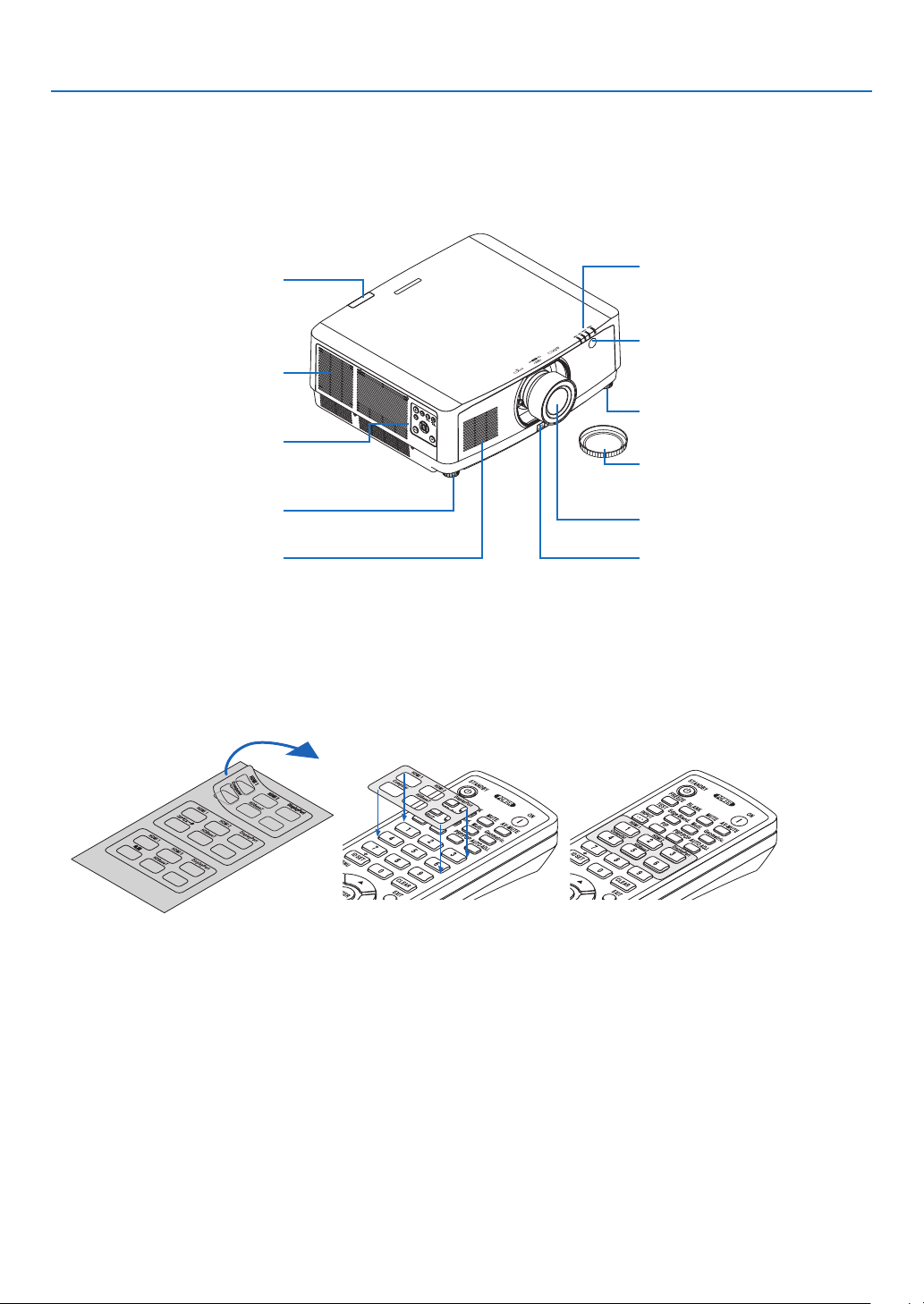
❸ Part Names of the Projector
Front/Top
The lens is sold separately. The description below is for when the NP41ZL lens is mounted.
1. Introduction
Remote Sensor
(→ page 12)
Exhaust vent
Heated air is exhausted from here.
Controls
(→ page 8)
Adjustable Tilt Foot
(→ page 26)
Intake vent
(→ page xi, 148)
Indicator Section
(→ page 8)
Remote Sensor (located on the
front and the rear)
(→ page 12)
Adjustable Tilt Foot
(→ page 26)
Lens Cap
(The optional lens is shipped with
the lens cap.)
Lens
Lens Release Button
(→ page 140)
How to paste the input selection character sticker of the remote control
• Peel off the cover of the sticker and align the sticker holes with Buttons 1 to 6 before pasting.
• Please take care not to let the sticker contact the buttons when pasting.
• The explanations and illustrations in this manual are provided with the sticker pasted.
5
1. Introduction
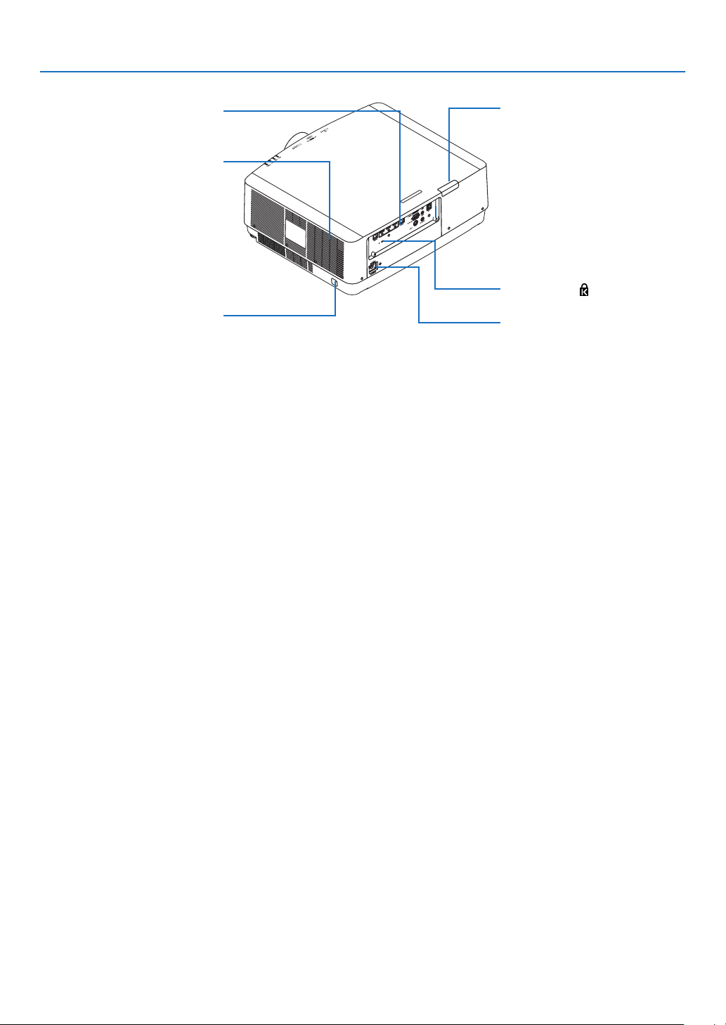
Rear
Terminals
(→ page 9)
Intake vent
(→ page xi, 148)
Security Bar
Attach an anti-theft device.
The security bar accepts security
wires or chains up to 0.18 inch/4.6
mm in diameter.
* Security and theft protection lock compatible with Kensington security cables/equipment. For products, visit Kens-
ington’s website.
Remote Sensor (located on the
front and the rear)
(→ page 12)
Security Slot ( )*
AC IN Terminal
Connect the supplied power cord’s
three-pin plug here, and plug the
other end into an active wall outlet.
(→ page 14)
6
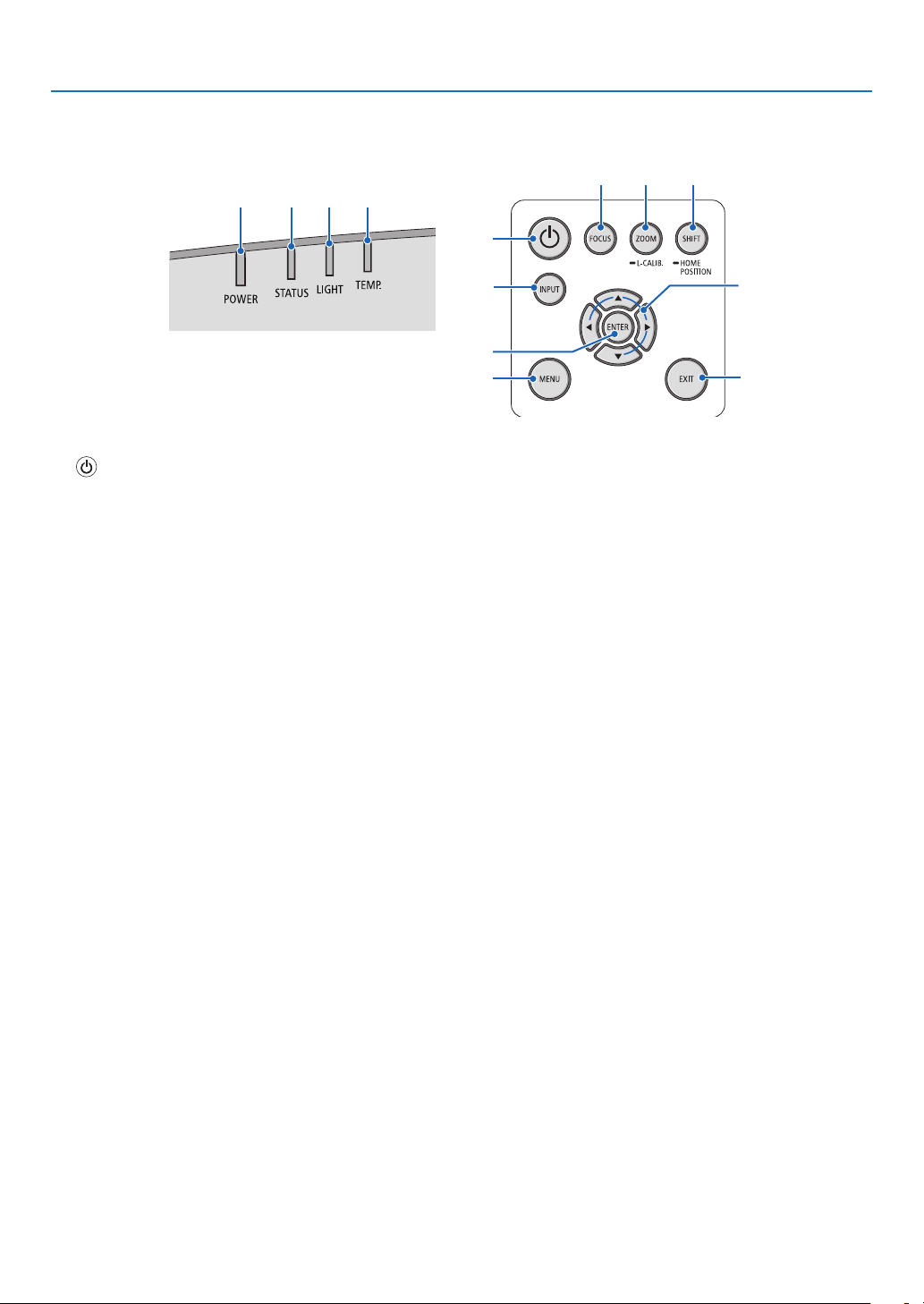
Controls/Indicator Panel
2 3 4 5
1. Introduction
11 12 13
1
1. (POWER) Button
(→ page 16, 28)
2. POWER Indicator
(→ page 14, 16, 28, 165, 166, 167)
3. STATUS Indicator
(→ page 165, 166, 167)
4. LIGHT Indicator
(→ page 165, 166, 167)
5. TEMP. Indicator
(→ page 165, 166, 167)
6. INPUT Button
(→ page 18)
7. MENU Button
(→ page 74)
8. ▲▼◀▶ / Volume Buttons ◀▶
(→ page 27, 74 )
9. ENTER Button
(→ page 74)
10. EXIT Button
(→ page 74)
11. FOCUS Button
(→ page 23)
12. ZOOM/L-CALIB. Button
(→ page 25)
13. SHIFT/HOME POSITION Button
(→ page 21)
6
8
9
7
10
7
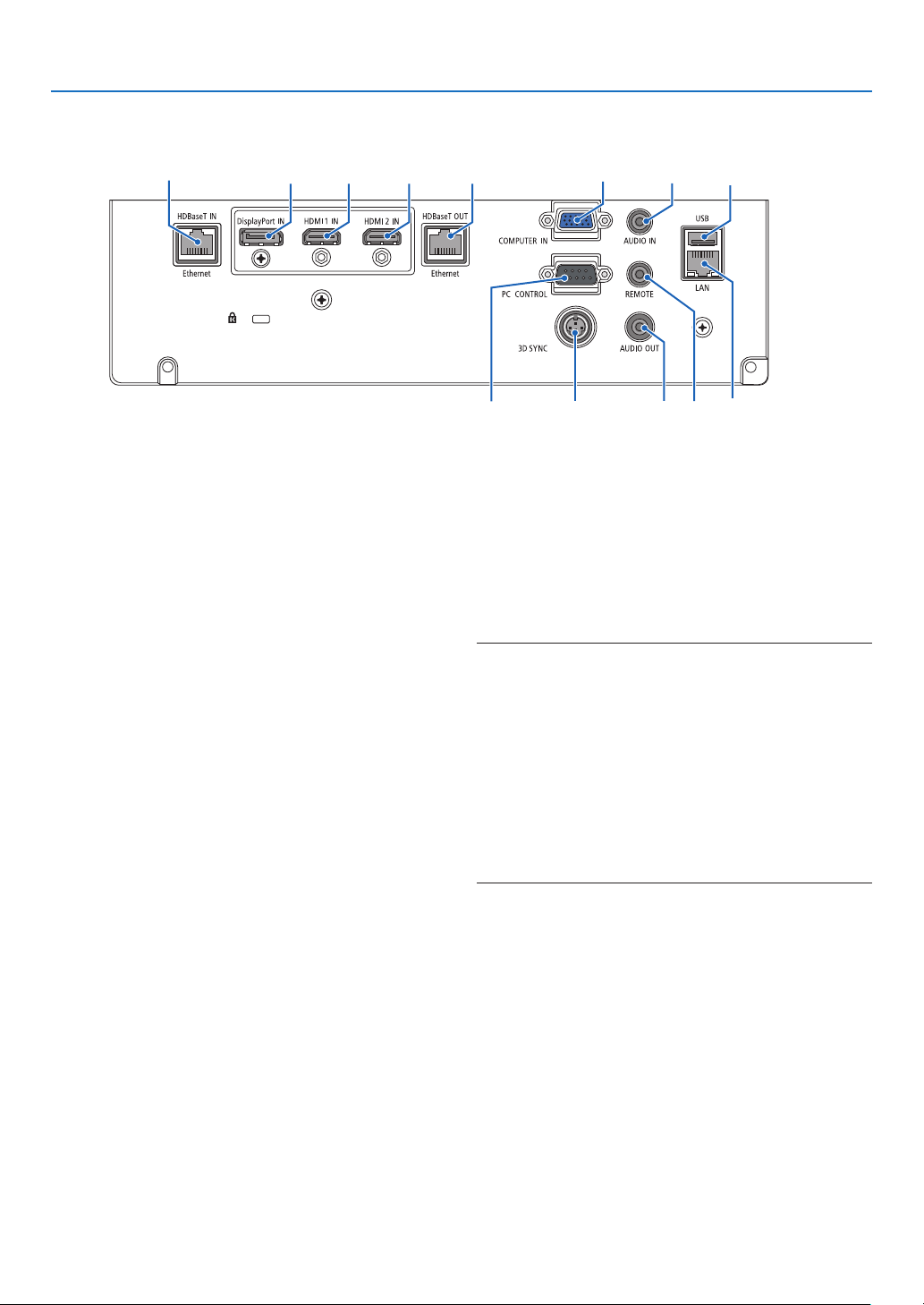
Terminals
1. Introduction
6 9
1. HDMI 1 IN Terminal (Type A)
(→ page 142, 143, 145)
2. HDMI 2 IN Terminal (Type A)
(→ page 142, 143, 145)
3. DisplayPort IN Terminal
(→ page 142)
4. COMPUTER IN/ Component Input Terminal (Mini
D-Sub 15 Pin)
(→ page 141, 144)
5. COMPUTER AUDIO IN Mini Jack (Stereo Mini)
(→ page 141, 143)
6. HDBaseT IN/Ethernet Port (RJ-45)
(→ page 146, 147)
7. HDBaseT OUT/Ethernet Port (RJ-45)
(→ page 61, 147)
8. AUDIO OUT Mini Jack (Stereo Mini)
(→ page 141, 143, 145)
9. USB-A Port (Type A)
(→ page 38)
10. LAN Port (RJ-45)
(→ page 150)
11. 3D SYNC Terminal (Mini DIN 3 Pin)
(→ page 44)
12. PC CONTROL Port (D-Sub 9 Pin)
(→ page 163)
Use this port to connect a PC or control system.
This enables you to control the projector using serial
communication protocol. If you are writing your own
program, typical PC control codes are on page 173.
2 73 1
4
12
13. REMOTE Terminal (Stereo Mini)
Use this terminal for wired remote control of the pro-
jector using the NEC remote control, RD-465E.
Connect the projector and our remote control, RD-
465E, using a commercially available wired remote
control cable.
NOTE:
• When a remote control cable is connected to the REMOTE
terminal, infrared remote control operations cannot be performed.
• When [HDBaseT] is selected in the [REMOTE SENSOR]
and the projector is connected to a commercially-available
transmission device that supports HDBaseT, remote control
operations in infra-red cannot be carried out if transmission
of remote control signals has been set up in the transmission
device. However, remote control using infrared rays can be
carried out when the power supply of the transmission device
is switched off.
5
811
13 10
8
❹ Part Names of the Remote Control
1
12
13
16
19
22
25
23
27
21
24
38
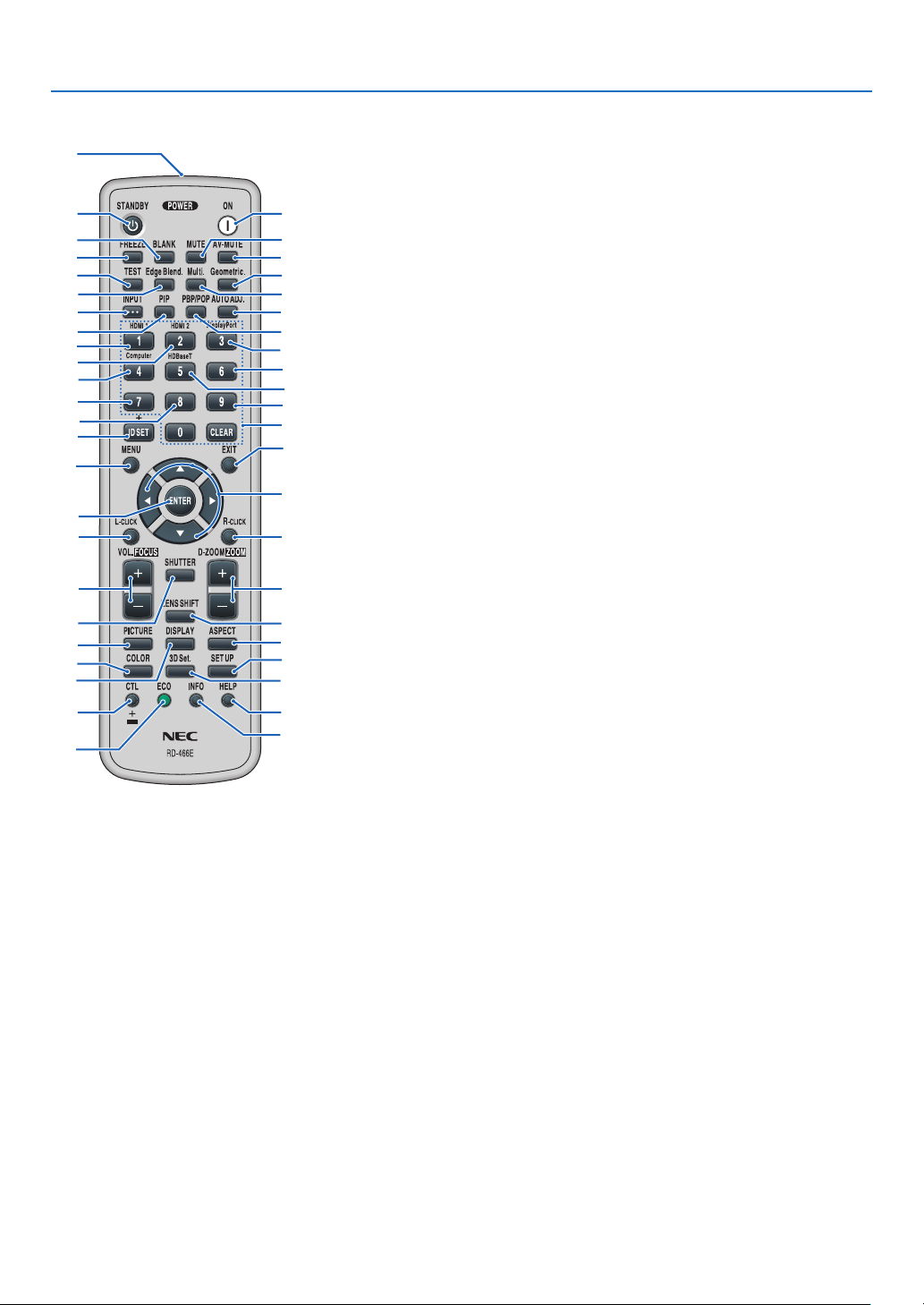
9. Edge Blend. Button
(→ page 69)
10. Multi. Button
2
(→ page 107)
6
11. Geometric. Button
7
(→ page 36, 101)
11
12. INPUT Button
10
15
(→ page 18)
14
13. PIP Button
18
(→ page 64)
14. PBP/POP Button
20
(→ page 64)
26
15. AUTO ADJ. Button
28
(→ page 27)
16. 1 (HDMI 1) Button
29
(→ page 18)
17. 2 (HDMI 2) Button
32
(→ page 18)
18. 3 (DisplayPort) Button
34
(→ page 18)
36
19. 4 (Computer) Button
39
(→ page 18)
42
20. 5 (HDBaseT) Button
41
(→ page 18)
46
21. 6 Button
45
(not available on this series of
projectors)
22. 7 Button
(not available on this series of
projectors)
23. 8 Button
(not available on this series of
projectors)
24. 9 Button
(not available on this series of
projectors)
25. ID SET Button
(→ page 121)
26. Numeric Keypad Button/
CLEAR Button
(→ page 121)
27. MENU Button
(→ page 74)
28. EXIT Button
(→ page 74)
3
5
4
8
9
17
30
31
33
35
37
40
43
44
1. Infrared Transmitter
(→ page 12)
2. POWER ON Button
(→ page 16)
3. STANDBY Button
(→ page 28)
4. FREEZE Button
(→ page 32)
5. BLANK Button
(→ page 30)
6. MUTE Button
(→ page 30)
7. AV-MUTE Button
(→ page 30)
8. TEST Button
(→ page 85)
* The ▲▼◀▶, L-CLICK and R-CLICK buttons work only when a USB cable is connected with your computer.
29. ▲▼◀▶ Button
(→ page 74)
30. ENTER Button
(→ page 74)
31. L-CLICK Button*
32. R-CLICK Button*
33. VOL./FOCUS (+)(−) Button
(→ page 23, 27)
34. D-ZOOM/ZOOM (+)(−) Button
(→ page 25, 32)
35. SHUTTER Button
(→ page 30)
36. LENS SHIFT Button
(→ page 21)
37. PICTURE Button
(→ page 86)
38. DISPLAY Button
(→ page 99)
39. ASPECT Button
(→ page 92)
40. COLOR Button
(→ page 88)
41. 3D Set. Button
(→ page 44)
42. SETUP Button
(→ page 109)
43. CTL Button
(→ page 23, 24, 25)
44. ECO Button
(→ page 33)
45. INFO Button
(→ page 134)
46. HELP Button
(→ page 133)
1. Introduction
9
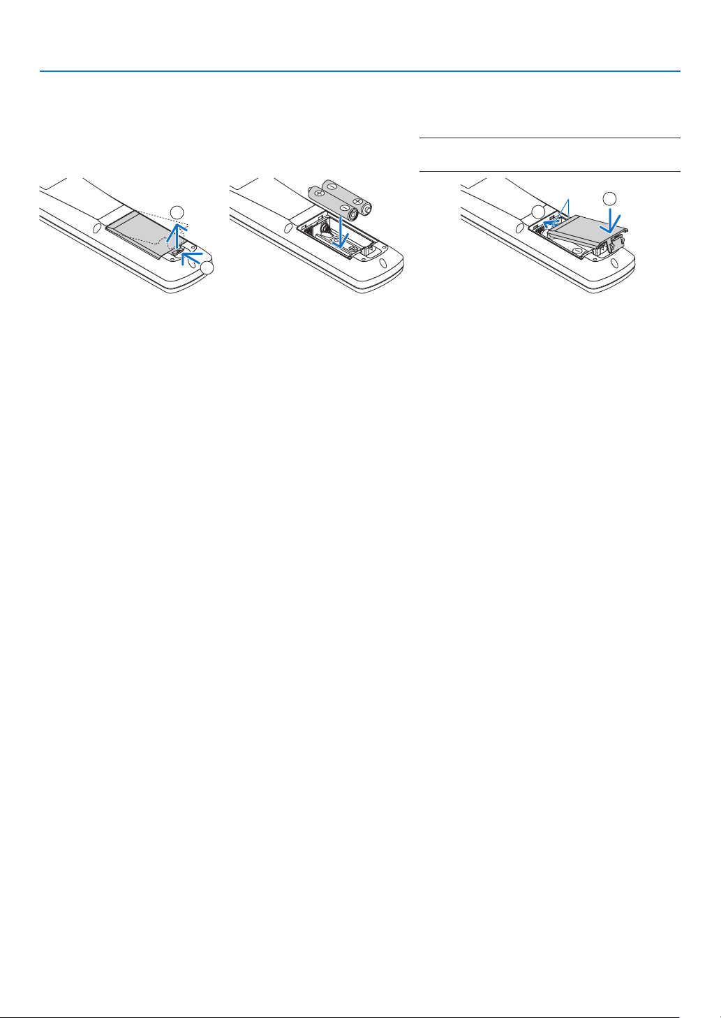
Battery Installation
1. Press the catch and remove
the battery cover.
2. Install new ones (AA). Ensure that you have the batteries’ polarity (+/−) aligned
correctly.
1. Introduction
3. Slip the cover back over the batteries until
it snaps into place.
NOTE: Do not mix different types of batteries or new
and old batteries.
2
1
Remote Control Precautions
• Handle the remote control carefully.
• If the remote control gets wet, wipe it dry immediately.
• Avoid excessive heat and humidity.
• Do not short, heat, or take apart batteries.
• Do not throw batteries into re.
• If you will not be using the remote control for a long time, remove the batteries.
• Ensure that you have the batteries’ polarity (+/−) aligned correctly.
• Do not use new and old batteries together, or use different types of batteries together.
• Dispose of used batteries according to your local regulations.
1
2
10
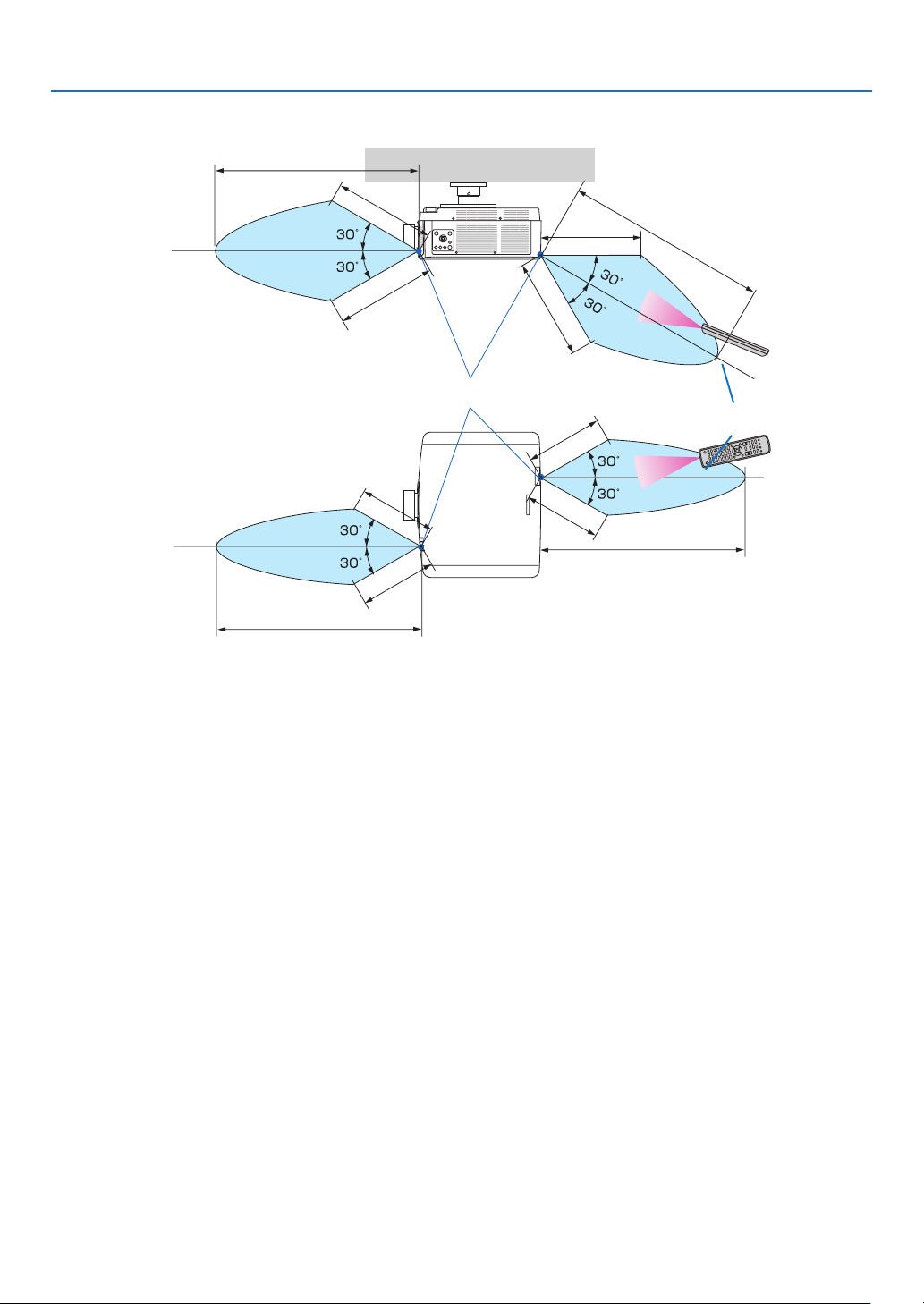
Operating Range for Wireless Remote Control
40 m/1575 inch
20 m/787 inch
20 m/787 inch
Remote sensor on projector cabinet
15 m/591 inch
15 m/591 inch
40 m/1575 inch
1. Introduction
40 m/1575 inch
20 m/787 inch
20 m/787 inch
Remote control
15 m/591 inch
15 m/591 inch
40 m/1575 inch
• The infrared signal operates by line-of-sight up to a distance of above meters and within a 60-degree angle of the
remote sensor on the projector cabinet.
• The projector will not respond if there are objects between the remote control and the sensor, or if strong light falls
on the sensor. Weak batteries will also prevent the remote control from properly operating the projector.
11

2. Projecting an Image (Basic Operation)
This section describes how to turn on the projector and to project a picture onto the screen.
❶ Flow of Projecting an Image
Step 1
• Connecting your computer / Connecting the power cord (→ page 14)
Step 2
• Turning on the projector (→ page 16)
Step 3
• Selecting a source (→ page 18)
Step 4
• Adjusting the picture size and position (→ page 20)
• Correcting keystone distortion [CORNERSTONE] (→ page 36, 101)
Step 5
• Adjusting a picture and sound
- Optimizing a computer signal automatically (→ page 27)
- Turning up or down volume (→ page 27)
Step 6
• Making a presentation
Step 7
• Turning off the projector (→ page 28)
Step 8
• After use (→ page 29)
12

2. Projecting an Image (Basic Operation)
❷ Connecting Your Computer/Connecting the Power Cord
1. Connect your computer to the projector.
This section will show you a basic connection to a computer. For information about other connections, see “6-2
Making Connections” on page 141.
Connect the display output terminal (mini D-sub 15 pin) on the computer to the computer video input terminal
on the projector with a commercially-available computer cable (with ferrite core) and then turn the knobs of the
connectors to secure them.
2. Connect the supplied power cord to the projector.
First connect the supplied power cord’s three-pin plug to the AC IN terminal of the projector, and then connect
another plug of the supplied power cord directly in the wall outlet. Do not use any plug converter.
CAUTION
• This equipment is designed to be used in the condition of the power cord connected to earth. If the power
cord is not connected to the earth, it may cause electric shock. Please make sure the power cord is earthed
properly.
• To prevent the power cord from coming loose, make sure that all the prongs of the power cord plug are fully
inserted into the AC IN terminal of the projector before using the power cord stopper. A loose contact of the
power cord may cause a re or electric shock.
Upon connecting the power cable, the POWER indicator of the projector will light in green. If there are no input
signals, the device will go into the standby state.
(In the state, standby mode is NORMAL.) (→ page 130)
To wall outlet
Make sure that the prongs are fully inserted into
both the AC IN and the wall outlet.
COMPUTER IN
Computer cable (with ferrite core)
(sold commercially)
13

2. Projecting an Image (Basic Operation)
CAUTION:
Parts of the projector may become temporarily heated if the projector is turned off with the POWER button or if the
AC power supply is disconnected during normal projector operation.
Use caution when picking up the projector.
Using the power cord stopper
To prevent the power cord from accidently removing from the AC IN of the projector, use the power cord stopper.
Required tool: Phillips screwdriver
1. Mount the power cord stopper over the power plug that connected
to the AC IN terminal.
2. Fasten the screw on the power cord stopper.
14

❸ Turning on the Projector
1. Remove the lens cap.
2. Press the (POWER) button on the projector cabinet
or the POWER ON button on the remote control.
WARNING
The projector produces a strong light. When turning on
the power, make sure no one within projection range is
looking at the lens.
2. Projecting an Image (Basic Operation)
The POWER indicator lit in green will start to blink in blue.
After that, the image will be projected onto the screen.
TIP:
• When the message “PROJECTOR IS LOCKED! ENTER YOUR
PASSWORD.” is displayed, it means that the [SECURITY]
feature is turned on. (→ page 41)
After you turn on your projector, ensure that the computer
or video source is turned on.
NOTE: A blue screen (blue background) is displayed when no signal
is being input (by factory default menu settings).
Performing Lens Calibration
After mounting the separately available lens unit or replacing
a lens unit, perform [LENS CALIBRATION] by holding to press
ZOOM/L-CALIB. button on the cabinet over two seconds.
Calibration corrects the adjustable zoom, shift, and focus
range. If calibration is not performed, you may not be able to
get the best focus and zoom even if you adjust the focus and
zoom for the lens.
Sleep state Blinking Power On
Blinking in green
Blinking blue
light
(→ page 165)
Steady blue
light
15

2. Projecting an Image (Basic Operation)
Note on Startup screen (Menu Language Select screen)
When you rst turn on the projector, you will get the Startup menu. This menu gives you the opportunity to select one
of the 30 menu languages.
To select a menu language, follow these steps:
1. Use the ▲, ▼, ◀ or ▶ button to select one of the 30
languages from the menu.
2. Press the ENTER button to execute the selection.
After this has been done, you can proceed to the menu
operation.
If you want, you can select the menu language later.
(→ [LANGUAGE] on page 78 and 109)
NOTE:
• If the message, [PLEASE SET "DATE AND TIME".] is shown, please set the current date and time. (→ page 120)
• In the case this message is not shown, the [DATE AND TIME SETTING] is recommended to complete.
• Keep the lens cap off the lens while the projector’s power is on.
If the lens cap is on, it could be warped due to high temperature.
• If the STATUS indicator lights orange with the power button pressed, the projector will not be turned on since the [CONTROL
PANEL LOCK] has been ON. Cancel the lock by turning it off. (→ page 120)
• While the POWER indicator is blinking blue in short cycles, the power cannot be turned off by using the power button.
16

2. Projecting an Image (Basic Operation)
❹ Selecting a Source
Selecting the computer or video source
NOTE: Turn on the computer or video source equipment connected to the projector.
Detecting the Signal Automatically
Press the INPUT button for 1 second or longer. The projector will search
for the available input source and display it. The input source will change
as follows:
HDMI1 → HDMI2 → DisplayPort → COMUPTER → HDBaseT → HDMI1
→ …
• Press it briey to display the [INPUT] screen.
Press the ▼/▲ buttons to match the target input terminal and then press
the ENTER button to switch the input. To delete the menu display in
the [INPUT] screen, press the MENU or EXIT button.
TIP: If no input signal is present, the input will be skipped.
Using the Remote Control
Press any one of the 1/HDMI 1, 2/HDMI 2, 3/DisplayPort, 4/Computer,
or 5/HDBaseT button.
17

2. Projecting an Image (Basic Operation)
Selecting Default Source
You can set a source as the default source so that it will be displayed each time the projector is turned on.
1. Press the MENU button.
The menu will be displayed.
2. Press the ▶ button to select [SETUP] and press the ▼ button or the ENTER button to select [BASIC].
3. Press the ▶ button to select [SOURCE OPTIONS] and press the ▼ button or the ENTER button.
4. Press the ▼ button three times to select [DEFAULT INPUT SELECT] and press the ENTER button.
The [DEFAULT INPUT SELECT] screen will be displayed.
(→ page 128)
5. Select a source as the default source, and press the ENTER button.
6. Press the EXIT button a few times to close the menu.
7. Restart the projector.
The source you selected in step 5 will be projected.
NOTE: Even when [AUTO] is turned on, the [HDBaseT] will not be automatically selected. To set your network as the default source,
select [HDBaseT].
TIP:
• When the projector is in Standby mode, applying a computer signal from a computer connected to the COMPUTER IN input will
power on the projector and simultaneously project the computer’s image.
([AUTO POWER ON SELECT] → page 130)
• On the Windows 7 keyboard, a combination of the Windows and P keys allows you to set up external display easily and quickly.
18

2. Projecting an Image (Basic Operation)
❺ Adjusting the Picture Size and Position
Use the lens shift dial, the adjustable tilt foot lever, the zoom and the focus ring to adjust the picture size and position.
In this chapter drawings and cables are omitted for clarity.
Adjusting the projected image’s vertical and horizontal
position
[Lens shift]
(→ page 21)
Finely adjusting the size of an image
[Zoom]
(→ page 25)
Adjusting the focus
[Focus]
(→ page 22)
Adjusting the projected image’s inclination
[Tilt foot]
(→ page 26)
19

2. Projecting an Image (Basic Operation)
Adjusting the vertical position of a projected image (Lens shift)
CAUTION
• Perform the adjustment from behind or from the side of the projector. Adjusting from the front could expose your
eyes to strong light which could injure them.
• Keep hands away from the lens mounting portion while performing a lens shift. Failure to do so could result in
ngers being pinched by the moving lens.
1. Press either SHIFT/HOME POSITION button on the cabinet or LENS
SHIFT button on the remote control.
The [LENS SHIFT] screen will be displayed.
2. Press the ▼▲◀▶ buttons to move the projected image.
• To set back the lens to the home position
Press and hold the SHIFT/HOME POSITION button over 2 seconds. The lens mounted on the projector goes
back to the home position. (roughly to the center position)
NOTE:
• If the lens is shifted to the maximum in the diagonal direction, the screen peripheral area will be dark or shaded.
20

2. Projecting an Image (Basic Operation)
TIP:
• The diagram below shows the lens shift adjustment range (orientation: desk/front).
50%V
Width of projected image
100%V
10%V
10%H10%H
100%H
20%H
20%H
Height of projected image
Description of symbols: V indicates vertical (height of the projected image), H indicates horizontal (width of the projected image).
Focus
Recommend to perform the focus adjustment after leaving the projector under the state the TEST PATTERN has
been projected for over 30 minutes.
Please refer to page 85 in the User’s Manual about the TEST PATTERN.
21
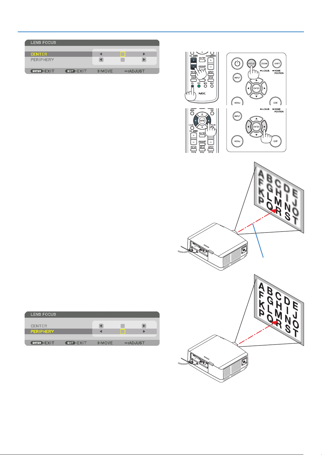
Applicable lens: NP40ZL/NP41ZL
1. Press the FOCUS button on the cabinet.
The LENS FOCUS control screen will be displayed on.
* Press ◀▶ buttons to adjust focus. In another way, press
and hold the CTL button and then press VOL./FOCUS
+/− button on the remote control
2. When the cursor is on the CENTER on on-screen menu,
press either ◀ or ▶ button to align focus around the
optical axis.
* The picture shows and example when the lens shift
is moved upward. The focus for the lower part of the
screen is aligned.
When the lens is at the center, the focus for the center
of the screen is aligned.
2. Projecting an Image (Basic Operation)
3. Press ▼ button to select the PERIPHERY on the onscreen menu, and then press either ◀ or ▶ button to
align the focus of screen peripheral area. During this
operation, the focus for around the optical axis will be
maintained.
22
Optical axis
2. Projecting an Image (Basic Operation)
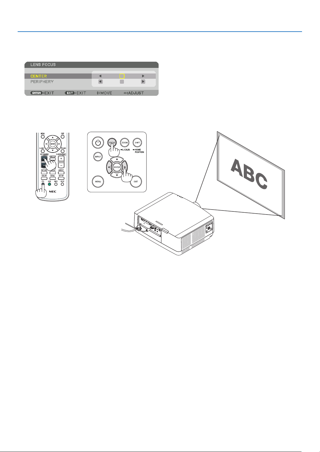
Applicable lens: NP43ZL
1. Press the FOCUS button on the cabinet.
Press ◀▶ buttons to adjust focus. In another way, press and hold the CTL button and then press VOL./FOCUS
+/− button on the remote control.
* PERIPHERY LENS FOCUS is not available for this lens unit.
23

2. Projecting an Image (Basic Operation)
Zoom
1. Press ZOOM/L-CALIB. button.
The ZOOM adjustment screen will be displayed on.
• ◀ or ▶ buttons on the cabinet or the remote control are available to adjust ZOOM while the ZOOM adjustment
screen is displayed on.
• On the remote control, while pressing on the CTL button, press the D-ZOOM/ZOOM (+) or (−) button.
The zoom is adjusted.
24

2. Projecting an Image (Basic Operation)
Adjusting the Tilt Foot
1. Turn the left and right tilt foot to adjust.
The tilt foot lengthen and shorten when turned.
Turn one of the tilt foot to adjust the image so that it is level.
• If the projected image is distorted, see “3-7 Correcting Horizontal
and Vertical Keystone Distortion [CORNERSTONE]” (→ page 36)
and “[GEOMETRIC CORRECTION]” (→ page 101).
• The tilt foot can be lengthened by a maximum of 10 mm/0.4".
• The tilt foot can be used to tilt the projector by a maximum of 1.4°.
NOTE:
• Do not lengthen the tilt foot any more than 10 mm/0.4". Doing so will make the
projector unstable.
• Do not use the tilt foot for any purpose other than adjusting inclination of the
projector installation angle.
Handling the tilt foot improperly, such as carrying the projector by grasping the
tilt foot or hooking it onto a wall using the tilt foot, could damage the projector.
Tilt foot
Up
Down
25
2. Projecting an Image (Basic Operation)
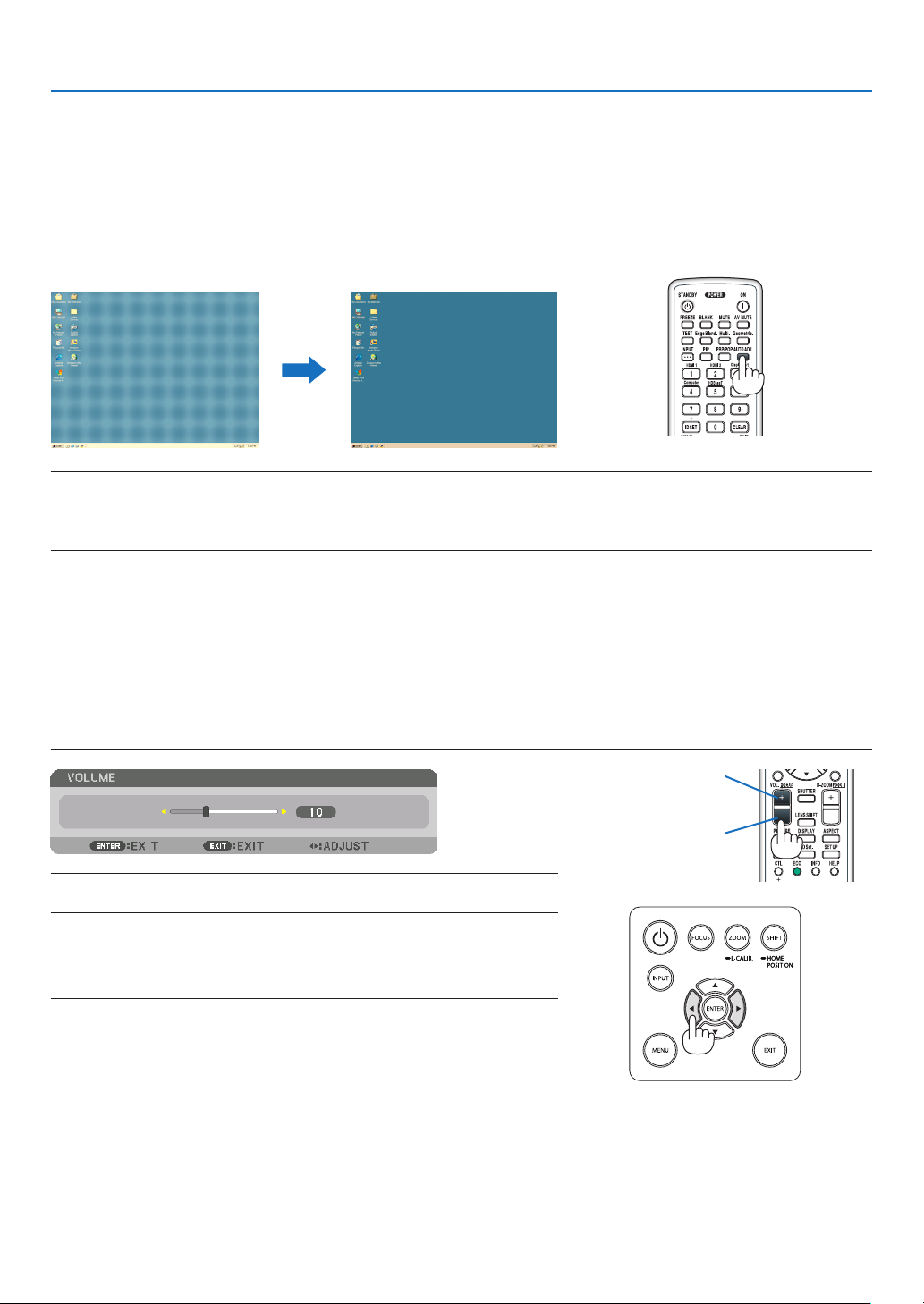
❻ Optimizing Computer Signal Automatically
Adjusting the Image Using Auto Adjust
When projecting a signal from the computer video input terminal, HDMI 1 IN terminal, HDMI 2 IN terminal, DisplayPort
IN terminal, HDBaseT IN/Ethernet port, adjust the picture quality with a single touch of the button if the edges of the
screen are cut off or if the projection quality is bad.
Press the AUTO ADJ. button to optimize a computer image automatically.
This adjustment may be necessary when you connect your computer for the rst time.
[Poor picture] [Normal picture]
NOTE:
Some signals may take time to display or may not be displayed correctly.
• If the Auto Adjust operation cannot optimize the computer signal, try to adjust [HORIZONTAL], [VERTICAL], [CLOCK], and [PHASE]
manually. (→ page 90, 91)
❼ Turning Up or Down Volume
Sound level from the AUDIO OUT terminal can be adjusted.
Important:
• Do not turn up the volume to the maximum level on the external speaker system connected to the AUDIO OUT of the projector.
Doing so may produce an unexpected, loud sound at the time of turning on or off the projector, causing damage to your hearing.
When adjusting the volume on the external speaker system, set volume level of the speaker system to less than half its rating and
adjust the volume on the projector to get appropriate sound level.
Increase volume
Decrease volume
TIP: When no menus appear, the ◀ and ▶ buttons on the projector cabinet work
as a volume control.
NOTE:
• Volume control is not available with the ◀ or ▶ button when an image is enlarged
by using the D-ZOOM (+) button or when the menu is displayed.
26
❽ Turning off the Projector
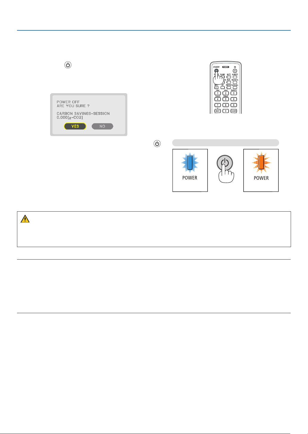
To turn off the projector:
1. First, press the (POWER) button on the projector
cabinet or the STANDBY button on the remote control.
The [POWER OFF / ARE YOU SURE ? / CARBON SAV-
INGS- SESSION 0.000[g-CO2]] message will appear.
2. Projecting an Image (Basic Operation)
2. Secondly, press the ENTER button or press the
(POWER) or the STANDBY button again.
The light source will be turned off and the power supply will
be cut. The projector will go to sleep state and the POWER
indicator will light in green. If no operation is performed
on the projector and no signal is input to the projector,
the projector will be in standby state. The POWER indicator will blilnk in orange (In the state, the standby mode is
NORMAL.).
Power On
Steadily lights in
blue
Standby
Blinks in orange
CAUTION:
Parts of the projector may become temporarily heated if the projector is turned off with the POWER button or if the
AC power supply is disconnected during normal projector operation.
Use caution when picking up the projector.
NOTE:
• While the POWER indicator is blinking blue in short cycles, the power cannot be turned off.
• You cannot turn off the power for 60 seconds immediately after turning it on and displaying an image.
• Do not unplug the power cord from the projector or from the power outlet while an image is being projected. Doing so could
deteriorate the projector’s AC IN terminal or the power plug’s contact. To turn off the AC power while an image is being projected,
use the power strip’s switch, the breaker, etc.
• Do not disconnect the AC power supply to the projector within 10 seconds of making adjustment or setting changes and closing
the menu. Doing so can cause loss of adjustments and settings.
27

❾ After Use
Preparation: Make sure that the projector is turned off.
2. Projecting an Image (Basic Operation)
1. Unplug the power cord.
2. Disconnect any other cables.
3. Mount the lens cap on the lens.
4. Before moving the projector, screw in the tilt foot if they
have been lengthened.
Loosen the screw counterclockwise until it starts
racing.
Draw off the power cord
stopper.
28

3. Convenient Features
❶ Turn off the light of the projector (LENS SHUTTER)
Press the SHUTTER button on the remote control.
The light source will turn off temporarily.
Press again to allow the screen to become illuminated again.
• You can set the projection light to gradually fade in or out.
❷ Turning off the Image and Sound
The projected video and the output sound from the sound output terminal
will disappear momentarily.
Press the BLANK button.
The projected video will be cut off.
Press the MUTE button.
The audio will be cut off.
Press the AV-MUTE button.
The projected video and audio will be cut off.
• Press the buttons one more time for the cancelled video and audio to
appear again.
TIP:
• The video will disappear but not the menu display.
29

3. Convenient Features
❸ Shift the On-Screen Menu displaying position
1. Press the MENU button.
The On-Screen Menu will be displayed on.
2. Move the cursor by the ▶ button to the [SETUP] and then press the ENTER button.
The cursor will move to the [MENU(1)].
3. Move the cursor by the ▶ button to the [MENU(2)].
4. Move the cursor by the ▼ button to the [MENU POSITION] and then press the ENTER.
The On-Screen Menu will go into the MENU POSITION setup screen.
5. Move the cursor either to [HORIZONTAL POSITION] or [VERTICAL POSITION] by pressing ▼ or ▲ button
and then press ◀/▶ button to shift the On-Screen Menu.
For finishing the setting on the On-Screen Menu, press the MENU button on the remote control.
TIP:
• Once the projector is powered off, the On-Screen Menu displaying position will be reset to the default factory setting position.
• This function does not influence to the display position of input terminal information and message.
• It enables to move the menu by mouse click when a commercially available USB mouse is connected.
• It enables to move the menu position by the ▼▲◀ and ▶ buttons holding to press the CTL button on the remote control or
mouse click.
• While the MENU POSITION of the on-screen menu is displayed on and the menu is moved by the ▼▲◀ and ▶ buttons holding
to press the CTL button on the remote control, the indication of adjusted value on the menu will not be changed. In this case,
close the MENU POSITION menu once and display it again for indicating the adjusted value properly.
30

❹ Freezing a Picture
Press the FREEZE button to freeze a picture. Press again to resume
motion.
NOTE: The image is frozen but the original video is still playing back.
❺ Enlarging a Picture
You can enlarge the picture up to four times.
NOTE:
• Depending on an input signal, the maximum magnification may be less than
four times, or the function may be restricted.
To do so:
1. Press the D-ZOOM (+) button to magnify the picture.
3. Convenient Features
2. Press the ▲▼◀▶ button.
The area of the magnified image will be moved
3. Press the D-ZOOM (−) button.
Each time the D-ZOOM (−) button is pressed, the image is reduced.
NOTE:
• The image will be enlarged or reduced at the center of the screen.
• Displaying the menu will cancel the current magnification.
31
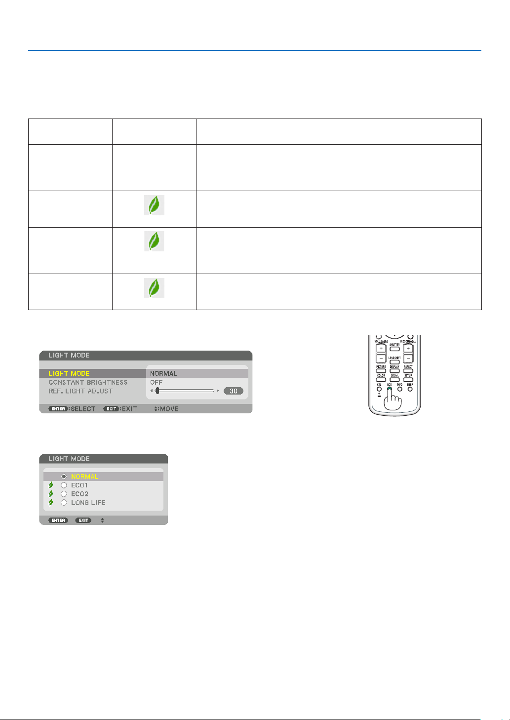
3. Convenient Features
❻ Changing LIGHT MODE/Checking Energy-Saving Effect
Using LIGHT MODE [LIGHT MODE]
When either [ECO1] or [ECO2] in [LIGHT MODE] is selected, motion noise of the projector is cut down by lowering
brightness of its light source.
LIGHT MODE
NORMAL 100% brightness
ECO1
ECO2
LONG LIFE
To turn on the [LIGHT MODE], do the following:
1. Press ECO button on the remote control.
Icon at the bottom
of the menu
Description
The screen will be brightly lit.
Depending on the installation circumstances, the service life of optical
parts may be shorten.
Brightness will be at about 80%.
The cooling fan will also slow down accordingly.
Lower power consumption
Brightness will be at about 60%.
The cooling fan will also slow down accordingly.
Lower power consumption considerably
More eco-friendly setting than NORMAL and ECO1.
Brightness is about 30%.
This setting speeds up the cooling fan and optimizes the service life of
the optical parts. The most eco-friendly setting among the options.
The [LIGHT MODE] screen will be displayed.
2. Press the ENTER button.
The [LIGHT MODE] selection screen will be displayed.
3. Use the ▼▲ buttons to make a selection, and press the ENTER
button.
The display will return to the [LIGHT MODE] screen and the selected
option will be applied.
Press the EXIT button to return to the original screen.
32

3. Convenient Features
NOTE:
• The [LIGHT MODE] can be changed by using the menu.
Select [SETUP] → [INSTALLATION(1)] → [LIGHT MODE] → [LIGHT MODE].
• The light module used hours can be checked in [USAGE TIME]. Select [INFO.] → [USAGE TIME].
• After a lapse of 1 minute from when the projector displays a blue, black or logo screen, the projector will automatically lower
the brightness to the equivalent level of [ECO2] when [NORMAL] or [ECO1] has been selected for [LIGHT MODE] and it will be
automatically back to the previous brightness when it detects input signal.
• If the [LIGHT MODE] is set to [NORMAL] or [ECO1], the brightness may be temporarily reduced depending on the operating
condition of the projector.
- When the room temperature reaches 33 °C or higher and the temperature inside the projector rises, the screen becomes darker
and darker in stages (equivalent to [ECO2]).
- Depending on the installation angle of the projector, the screen may become dark.
This is one of the protection functions called “Forced ECO MODE”. When “Forced ECO MODE” is in operation, the TEMP. Indica-
tor lights up in orange. At the same time, the Thermometer symbol [
temperature inside the projector decreases due to the room temperature being lowered, cancelling the “Forced ECO MODE” and
returning to the original brightness. In the “Forced ECO MODE”, the status does not change even if the [LIGHT MODE] setting is
changed.
] is displayed at the lower right of the menu screen. The
33

3. Convenient Features
Checking Energy-Saving Effect [CARBON METER]
This feature will show energy-saving effect in terms of CO2 emission reduction (kg) when the projector’s [LIGHT MODE]
is set to either [ECO1], [ECO2], or [LONG LIFE]. This feature is called as [CARBON METER].
There are two messages: [TOTAL CARBON SAVINGS] and [CARBON SAVINGS-SESSION]. The [TOTAL CARBON
SAVINGS] message shows the total amount of CO2 emission reduction from the time of shipment up to now. You can
check the information on [USAGE TIME] from [INFO.] of the menu. (→ page 133)
The [CARBON SAVINGS-SESSION] message shows the amount of CO2 emission reduction between the time of
changing to LIGHT MODE immediately after the time of power-on and the time of power-off. The [CARBON SAVINGSSESSION] message will be displayed in the [POWER OFF/ ARE YOU SURE ?] message at the time of power-off.
TIP:
• The formula shown below is used to calculate the amount of CO2 emission reduction. Amount of CO2 emission reduction = (Power
consumption in [NORMAL] LIGHT MODE – Power consumption in current setting) × CO
MODE] to [ECO1], [ECO2], or [LONG LIFE] increases CO
emissions savings.
2
conversion factor.* Setting the [LIGHT
2
* Calculation for amount of CO2 emission reduction is based on an OECD publication “CO2 Emissions from Fuel Combustion,
2008 Edition”.
• The [TOTAL CARBON SAVINGS] is calculated based on savings recorded in 15 minutes intervals.
• This formula will not apply to the power consumption which is not affected by whether [LIGHT MODE] is turned on or off.
34

3. Convenient Features
❼ Correcting Horizontal and Vertical Keystone Distortion
[CORNERSTONE]
Use the [CORNERSTONE] feature to correct keystone (trapezoidal) distortion to make the top or bottom and the left
or right side of the screen longer or shorter so that the projected image is rectangular.
1. Project an image so that the screen is smaller than the area of the raster.
The drawing shows the upper right corner.
Projected image
2. Pick up any one of the corners and align the corner of the image with a corner of the screen.
3. Press the Geometric. button either on the cabinet or the remote control.
Display the [GEOMETRIC CORRECTION] screen of the on-screen menu.
4. Move the cursor onto [MODE] by ▼ button and press the ENTER.
The mode selection screen will displayed on.
5. Select [CORNERSTONE] and press the ENTER.
Go back to display the [GEOMETRIC CORRECTION] screen of the on-screen menu.
35

3. Convenient Features
6. Press the ▼ button to align with the [CORNERSTONE] and then press the ENTER button.
The drawing shows the upper left icon ( ) is selected.
The screen will switch to the [CORNERSTONE] screen.
7. Use the ▲▼◀▶ button to select one icon (▲) which points in the direction you wish to move the projected
image frame.
8. Press the ENTER button.
9. Use the ▲▼◀▶ button to move the projected image frame as shown on the example.
10
. Press the ENTER button.
11
. Use the ▲▼◀▶ button to select another icon which points in the direction.
On the [CORNERSTONE] screen, select [EXIT] or press the EXIT button on the remote control.
36

3. Convenient Features
The confirmation screen is displayed.
12
. Press the ◀ or ▶ button to highlight the [OK] and press the ENTER button.
This completes the [CORNERSTONE] correction.
• Select [CANCEL] and press the ENTER button to return to the [CORNERSTONE] screen.
Selecting [CANCEL] will return to the adjustment screen without saving changes (Step 3).
Selecting [RESET] will return to the factory default.
Selecting [UNDO] will exit without saving changes.
NOTE:
• Even when the projector is turned on, the last used correction values are applied.
• Carry out either one of the following actions to clear the adjustment value of [CORNERSTONE].
• In Step 11, select [RESET] and then press the ENTER button.
• In the state [CORNERSTONE] has been selected for [MODE] in the [GEOMETRIC CORRECTION]:
• Press the Geometric. button for 2 or more seconds.
• Run [DISPLAY] → [GEOMETRIC CORRECTION] → [RESET] in the on-screen menu.
• Using CORNERSTONE correction can cause the image to be slightly blurred because the correction is made electronically.
• A commercially available USB mouse is available for CORNERSTONE correction.
❽ Operation for the On-Screen Menu by a commercially
available USB mouse
Once a commercially available USB mouse is connected to this projector, it enables to perform the operation for the
on-screen menu and the geometric correction easily.
NOTE:
• Not guarantee the performance of all USB mouse available on the market.
Menu operation
1. Display the on-screen menu by right click.
2. Select a desired menu and perform adjustment by left click.
The adjustment bar can be control by drag and drop.
37
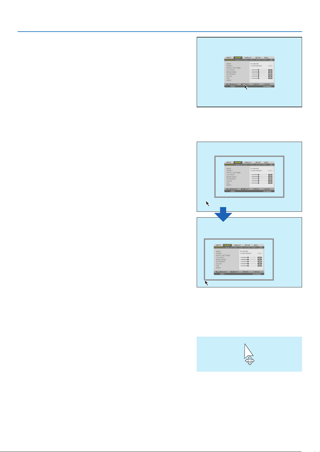
3. Select [EXIT] displayed at the bottom of the menu by left click
for going back to the previous level. If the cursor is on the main
menu option, it works for closing the menu. (It works as the same
performance with the [EXIT] button on the remote control.
Menu position control
1. Click the wheel button to display the on-screen menu indication
frame.
2. Left click at the position on the projection screen where you want
to shift the on-screen menu. The nearest corner of the on-screen
menu indication frame will shift to the clicked position.
3. Convenient Features
3. Click the wheel button to close the menu indication frame.
Geometric correction
The USB mouse can be used for CORNERSTONE CORRECTION, HORIZONTAL CORNER, VERTICAL CORNER
and WARP. In this clause, the CORNERSTONE CORRECTION by an USB mouse is explained as an example.
1. While the adjustment screen of the CORNERSTONE
CORRECTION is displayed, right click on the projection screen. The shape of mouse pointer will be
changed and the correction will become available.
38
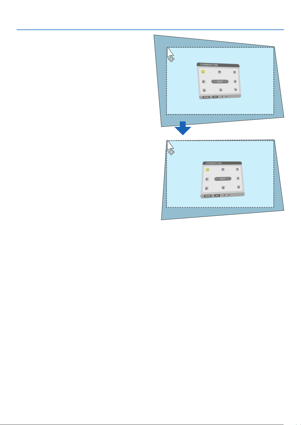
2. Left click at the screen corner. The projection screen
corner will move to the mouse clicked position.
3. Repeat the step 2 for correcting all distortion. After
completion of distortion correction, right click on
the projection screen. The shape of mouse pointer
will be changed to normal.
3. Convenient Features
4. Left click [EXIT] on the correction screen to finish.
39
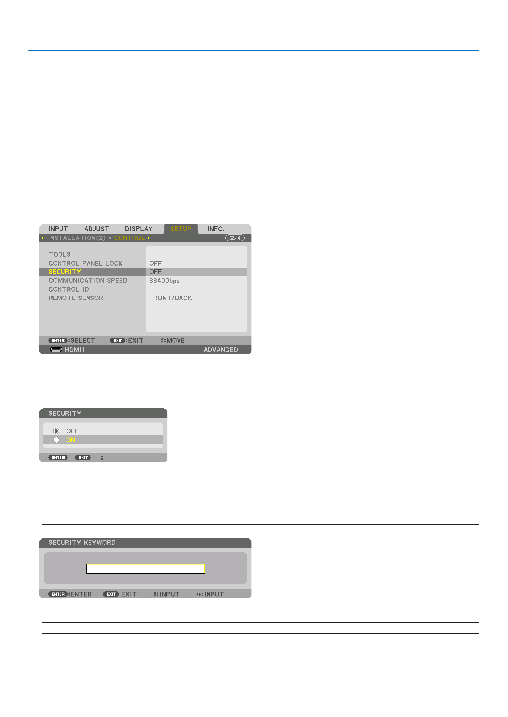
3. Convenient Features
❾
Preventing the Unauthorized Use of the Projector [SECURITY]
A keyword can be set for your projector using the Menu to avoid operation by an unauthorized user. When a keyword
is set, turning on the projector will display the Keyword input screen. Unless the correct keyword is entered, the projector cannot project an image.
• The [SECURITY] setting cannot be cancelled by using the [RESET] of the menu.
To enable the Security function:
1. Press the MENU button.
The menu will be displayed.
2. Press the ▶ button twice to select [SETUP] and press the ▼ button or the ENTER button to select [MENU(1)].
3. Press the ▶ button to select [CONTROL].
4. Press the ▼ button three times to select [SECURITY] and press the ENTER button.
The OFF/ON menu will be displayed.
5. Press the ▼ button to select [ON] and press the ENTER button.
The [SECURITY KEYWORD] screen will be displayed.
6. Type in a combination of the four ▲▼◀▶ buttons and press the ENTER button.
NOTE: A keyword must be 4 to 10 digits in length.
The [CONFIRM KEYWORD] screen will be displayed.
NOTE: Make a note of your password and store it in a safe place.
40
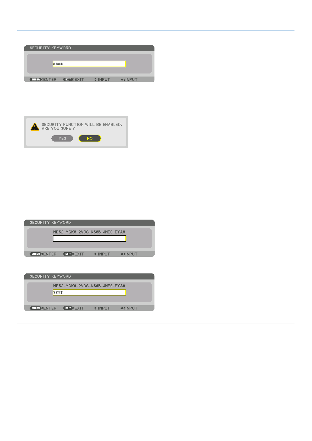
3. Convenient Features
7. Type in the same combination of ▲▼◀▶ buttons and press the ENTER button.
The confirmation screen will be displayed.
8. Select [YES] and press the ENTER button.
The SECURITY function has been enabled.
To turn on the projector when [SECURITY] is enabled:
1. Press the POWER button.
The projector will be turned on and display a message to the effect that the projector is locked.
2. Press the MENU button.
3. Type in the correct keyword and press the ENTER button. The projector will display an image.
NOTE: The security disable mode is maintained until the main power is turned off or unplugging the power cord.
41
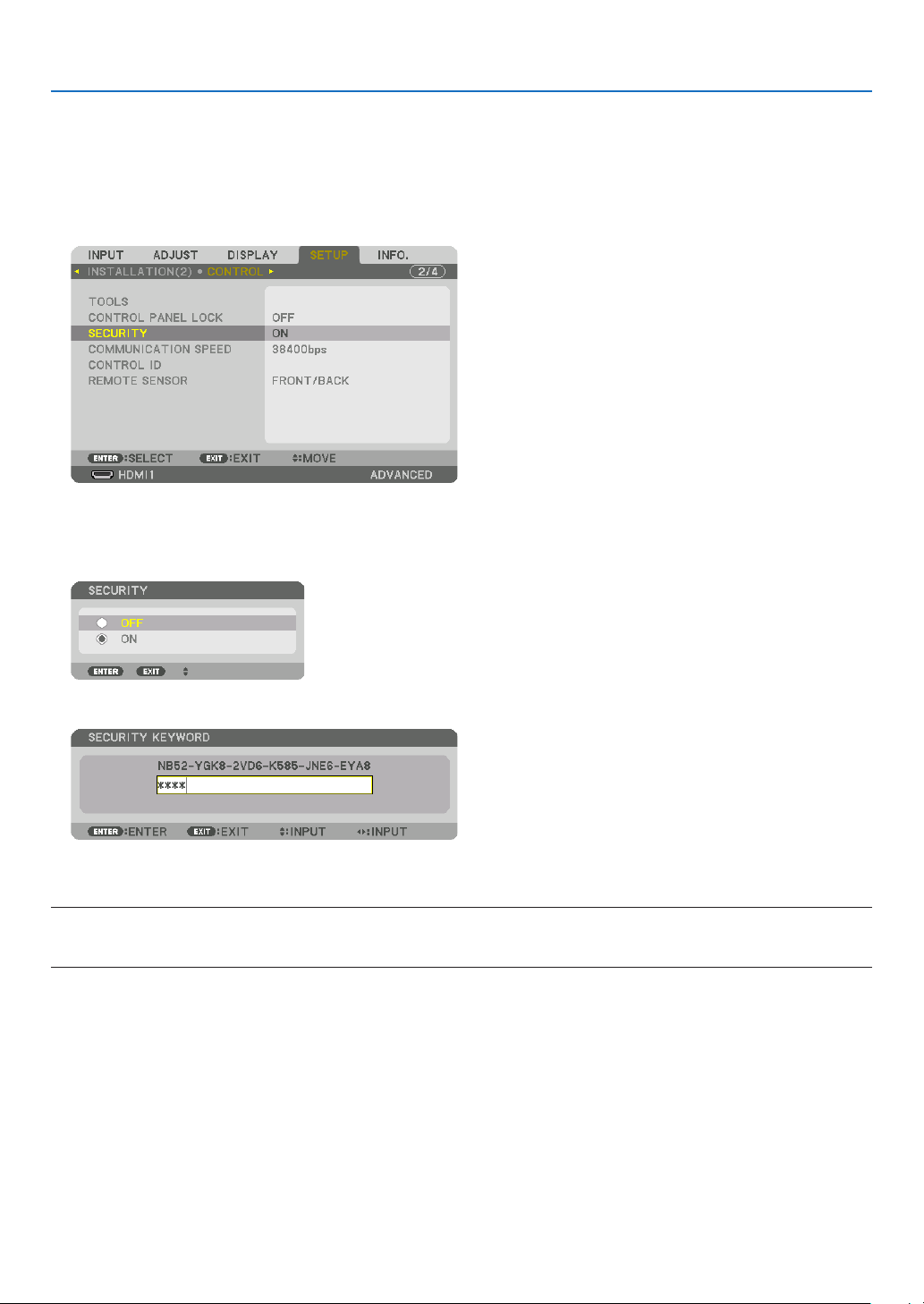
To disable the SECURITY function:
1. Press the MENU button.
The menu will be displayed.
2. Select [SETUP] → [CONTROL] → [SECURITY] and press the ENTER button.
The OFF/ON menu will be displayed.
3. Select [OFF] and press the ENTER button.
3. Convenient Features
The SECURITY KEYWORD screen will be displayed.
4. Type in your keyword and press the ENTER button.
When the correct keyword is entered, the SECURITY function will be disabled.
NOTE: If you forget your keyword, contact your dealer. Your dealer will provide you with your keyword in exchange for your request
code. Your request code is displayed in the Keyword Confirmation screen. In this example [NB52-YGK8-2VD6-K585-JNE6-EYA8]
is a request code.
42
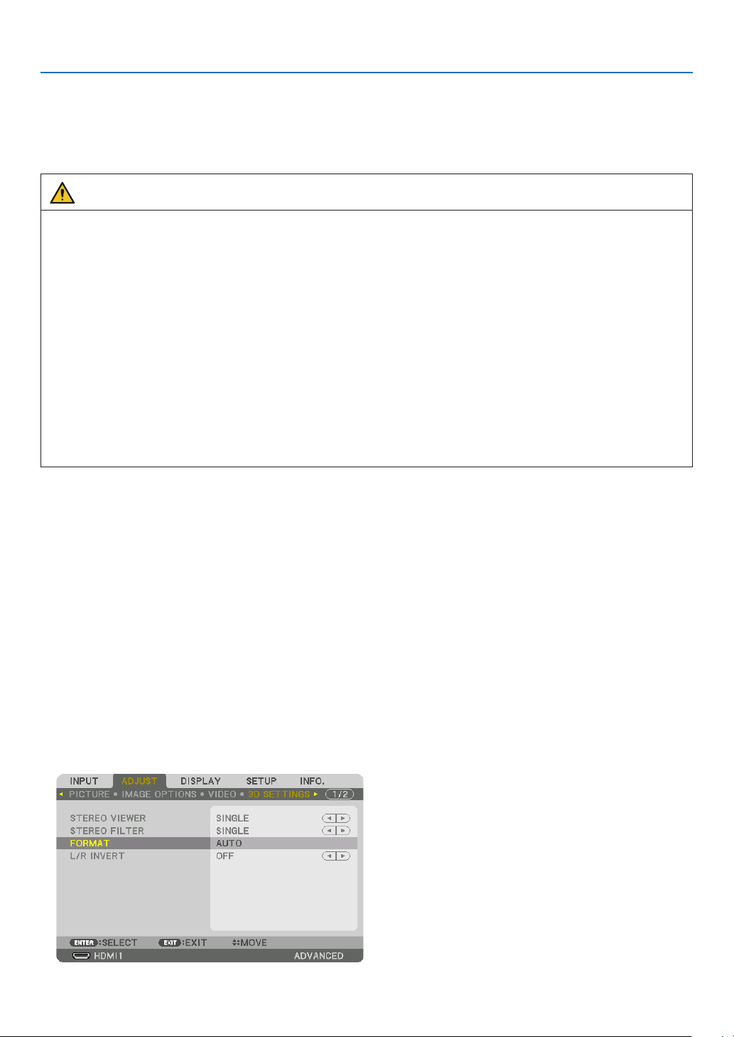
3. Convenient Features
❿ Projecting 3D videos
This projector can be used to watch videos in 3D using commercially-available active shutter-type 3D eyewear. In
order to synchronize the 3D video and eyewear, a commercially-available 3D emitter needs to be connected to the
projector (on the projector side).
The 3D eyewear receives information from the 3D emitter and performs opening and closing on the left and right.
CAUTION
Health precautions
Before use, please make sure to read any health precautions that may be stated in the operating manuals enclosed
with the 3D eyewear and 3D video software (Blu-ray player, games, computer animation les, etc.).
Please take note of the following in order to avoid adverse health effects.
• Please do not use the 3D eyewear for purposes other than to watch 3D videos.
• Please keep a distance of at least 2 m away from the screen when watching videos. Watching a video too close
to the screen will increase eye fatigue.
• Please do not watch videos continuously for a long period of time. Please take a 15 minutes’ break after every
hour of watching.
• Please consult a doctor before watching if you or any of your family members have a history of suffering from
seizures caused by light sensitivity.
• Please stop watching immediately and take a rest when you feel physically unwell while watching (vomiting, giddiness, nausea, headaches, sore eyes, blurred vision, cramps and dumbness in the limbs, etc.). Please consult
a doctor if the symptoms persist.
• Please watch a 3D video directly in front of the screen. If you watch a 3D video obliquely from the sides, this
may result in physical and eye fatigue.
3D eyewear and 3D emitter preparations
Please use an active shutter-type 3D eyewear that conforms with the VESA standard.
A commercially-available RF type made by Xpand is recommended.
3D eyewear ������������ Xpand X105-RF
3D emitter
�������������� Xpand AD025-RF-X1
Procedure to watch 3D videos using this projector
1. Connect the video device to the projector.
2. Switch on the power supply to the projector.
3. Run the 3D video software and project the video using the projector.
This has been automatically set up when shipped from the factory. When a 3D video cannot be projected, it may
be because the 3D detection signals are not included or because they are not detectable by the projector.
Please manually select the format.
4. Select the 3D video format.
(1) Press the “3D Set.” button on the remote control.
43

3. Convenient Features
The [3D SETTINGS] screen will be displayed.
(2) Press the ▼ button to align the cursor with the [FORMAT] and press the ENTER button.
The format screen will be displayed.
(3) Select the input signal format using the ▼ button and then press the ENTER button.
The 3D settings screen will disappear and the 3D video will be projected.
Press the MENU button and the on-screen menu will disappear.
The 3D caution message screen will be displayed when switching to a 3D video (default factory setting when
shipped). Please read the “Health Precautions” on the previous page to watch videos in the correct manner. The
screen will disappear after 60 seconds or when the ENTER button is pressed. (→ page 109)
5. Turn on the power supply of the 3D eyewear and wear the eyewear to watch the video.
A normal video will be shown when a 2D video is input.
To watch a 3D video in 2D, select [OFF(2D)] in the [FORMAT] screen mentioned above in (3).
NOTE:
• Upon switching to 3D image, the following functions will be cancelled and disabled. [BLANKING], [PIP/PICTURE BY PICTURE],
[GEOMETRIC CORRECTION], [EDGE BLENDING] ([GEOMETRIC CORRECTION] and [EDGE BLENDING] adjustment values will
be maintained.)
• The output may not automatically switch to a 3D video depending on the 3D input signal.
• Check the operating conditions described in the user manual of the Blu-ray player.
• Please connect the DIN terminal of the 3D emitter to the 3D SYNC of the main projector.
• The 3D eyewear allows videos to be viewed in 3D by receiving synchronized optical signals output from the 3D emitter.
As a result, the 3D image quality may be affected by conditions such as the brightness of the surroundings, screen size, viewing
distance, etc.
• When playing a 3D video software on a computer, the 3D image quality may be affected if the computer CPU and graphics chip
performance are low. Please check the required operating environment of the computer that is stated in the operating manual
attached to the 3D video software.
• Depending on the signal, [FORMAT] and [L/R INVERT] may not be able to be selected. Please change the signal in that case.
44

3. Convenient Features
When videos cannot be viewed in 3D
Please check the following points when videos cannot be viewed in 3D.
Please also read the operating manual attached to the 3D eyewear.
Possible reasons Solutions
The selected signal does not support 3D output� Please change the video signal input to one that supports 3D�
The format for the selected signal is turned to [OFF(2D)]� Please change the format in the on-screen menu to [AUTO] or a
A eyewear that is not supported by the projector is being used� Please purchase a commercially-available 3D eyewear or 3D emitter
Please check the following points when a video cannot be viewed in
3D using a 3D eyewear that is supported by the projector�
The power supply of the 3D eyewear is turned off� Please turn on the power supply of the 3D eyewear�
The internal battery of the 3D eyewear is flat� Please charge or replace the battery�
The viewer is located too far away from the screen� Please get closer to the screen until the video can be seen in 3D�
Due to multiple 3D projectors working at the same time in the vicinity, the projectors may interfere with one another� Alternatively,
there may be a bright light source near the screen�
There is an obstacle between the optical receiver of the 3D eyewear
and the 3D emitter�
The 3D format of the 3D video contents is not supported� Please check with the company selling the 3D video contents�
format that supports 3D�
(recommended)� (→ page 44)
Please turn the L/R INVERT in the on-screen menu to [OFF]�
Please maintain sufficient distance between the projectors�
Please keep the light source away from the screen�
Please turn the L/R INVERT in the on-screen menu to [OFF]�
Please remove the obstacle�
45

3. Convenient Features
⓫ Controlling the Projector by Using an HTTP Browser
Overview
Using the web browser on the computer, the HTTP server screen of the projector can be displayed to operate the
projector.
Possible operations on the HTTP server screen
• Congure the settings required for connecting the projector to the network (wired LAN). (NETWORK SETTINGS)
• Congure the email notication. (ALERT MAIL)
When the projector is connected to a network (wired LAN), notications on various errors are sent to the email
address that has been set up.
• Operate the projector.
Operations such power on/off of the projector, input terminal switchover, volume control, picture control, and lens
control etc. can be carried out.
• Congure the [PJLink PASSWORD], [AMX BEACON], and [CRESTRON] etc.
To view the HTTP server screen
1. Connect the projector to the computer with a LAN cable sold commercially. (→ page 150)
2. Select [SETUP] → [NETWORK SETTINGS] → [WIRED LAN] in the on-screen menu to configure the network
settings. (→ page 124)
3. Start up the web browser on your computer and enter the address or URL in the input field.
Specify the address or URL as “http://<IP Address of Projector>/index.html”.
The basic HTTP server screen will be displayed.
TIP: The factory setting IP address is [DHCP ON].
NOTE:
• To use the projector in a network, consult with your network administrator about network settings.
• The display’s or button’s response can be slowed down or operation may not be accepted depending the settings of your network.
Should this happen, consult your network administrator. The projector may not respond if its buttons are repeatedly pressed in
rapid intervals. Should this happen, wait a moment and repeat. If you still can’t get any response, turn off and back on the projector.
• If the PROJECTOR NETWORK SETTINGS screen does not appear in the web browser, press the Ctrl+F5 keys to refresh your web
browser (or clear the cache).
• This projector uses “JavaScript” and “Cookies” and the browser should be set to accept these functions. The setting method will
vary depending on the version of browser. Please refer to the help files and the other information provided in your software.
Preparation before Use
Connect the projector to a commercially available LAN cable before engaging in browser operations. (→ page 150)
Operation with a browser that uses a proxy server may not be possible depending on the type of proxy server and the
setting method. Although the type of proxy server will be a factor, it is possible that items that have actually been set
will not be displayed depending on the effectiveness of the cache, and the contents set from the browser may not be
reected in operation. It is recommended that a proxy server not be used unless it is unavoidable.
46

3. Convenient Features
Handling of the Address for Operation via a Browser
Regarding the actual address that is entered for the address or entered to the URL column when operation of the
projector is via a browser, the host name can be used as it is when the host name corresponding to the IP address
of the projector has been registered to the domain name server by a network administrator, or the host name corresponding to the IP address of the projector has been set in the “HOSTS” le of the computer being used.
Example 1: When the host name of the projector has been set to “pj.nec.co.jp”, access is gained to the network
setting by specifying
http://pj.nec.co.jp/index.html
for the address or the entry column of the URL.
Example 2: When the IP address of the projector is “192.168.73.1”, access is gained to the network setting by
specifying
http://192.168.73.1/index.html
for the address or the entry column of the URL.
PROJECTOR ADJUSTMENT
POWER: This controls the power of the projector.
ON
������������������������� Power is switched on�
OFF ������������������������ Power is switched off�
VOLUME: This controls the volume of the projector.
▲ ��������������������������� Increases the volume adjustment value for the AUDIO OUT terminal�
▼ ��������������������������� Decreases the volume adjustment value for the AUDIO OUT terminal�
AV-MUTE: This controls the mute function of the projector.
PICTURE ON ���������� Mutes the video�
PICTURE OFF ��������� Cancels the video muting�
SOUND ON ������������ Mutes the audio from the AUDIO OUT terminal�
SOUND OFF ����������� Cancels the audio muting from the AUDIO OUT terminal�
ALL ON ������������������ Mutes each of the video, and audio functions for the AUDIO OUT terminal�
ALL OFF ����������������� Cancels the muting of each of the video, and audio functions for the AUDIO OUT terminal�
47

3. Convenient Features
PICTURE: Controls the video adjustment of the projector.
BRIGHTNESS ▲ ���� Increases the brightness adjustment value�
BRIGHTNESS ▼ ���� Decreases the brightness adjustment value�
CONTRAST ▲ �������� Increases the contrast adjustment value�
CONTRAST ▼ �������� Decreases the contrast adjustment value�
COLOR ▲ �������������� Increases the color adjustment value�
COLOR ▼ �������������� Decreases the color adjustment value�
HUE ▲ ������������������� Increases the hue adjustment value�
HUE ▼ ������������������� Decreases the hue adjustment value�
SHARPNESS ▲ ����� Increases the sharpness adjustment value�
SHARPNESS ▼ ����� Decreases the sharpness adjustment value�
• The functions that can be controlled will vary depending on the signal being input to the projector. (→ page 88,
89)
SOURCE SELECT: This switches the input connector of the projector.
HDMI1
������������������� Switches to the HDMI 1 IN connector�
HDMI2 ������������������� Switches to the HDMI 2 IN connector�
DisplayPort ������������ Switches to the DisplayPort�
COMPUTER ����������� Switches to the COMPUTER IN connector�
HDBaseT ���������������� Switch to image input sent from a transmission device that supports HDBaseT�
PROJECTOR STATUS: This displays the condition of the projector.
LIGHT HOURS USED ���������� Displays how many hours the light module has been used�
ERROR STATUS ������������������ Displays the status of errors occurring within the projector�
LOG OFF: Logging off your projector and returning to the authentication screen (LOGON screen).
48

3. Convenient Features
NETWORK SETTINGS
http://<IP Address of Projector (Basic)>/index.html
• SETTINGS
WIRED LAN
INTERFACE Select [LAN] for connecting LAN by wire thru the LAN port.
Select [HDBaseT] for connecting LAN by wire thru the HDBaseT IN/Ethernet port.
SETTING Set for wired LAN.
PROFILE 1/PROFILE 2 Two settings can be set for wired LAN connection. Select PROFILE 1 or PROFILE 2.
DISABLE Turn off wired LAN connection. The POWER indicator that is informing the STANDBY
state will start to blink in orange long interval (→ page 165).
DHCP ON Automatically assign IP address, subnet mask, and gateway to the projector from your
DHCP server.
DHCP OFF Set IP address, subnet mask, and gateway to the projector assigned by your network
administrator.
IP ADDRESS Set your IP address of the network connected to the projector.
SUBNET MASK Set your subnet mask number of the network connected to the projector.
GATEWAY Set the default gateway of the network connected to the projector.
AUTO DNS ON DHCP server will automatically assign IP address of DNS server connected to the
projector.
AUTO DNS OFF Set your IP address assigned by your network administrator.
DNS Set your IP address of DNS server connected to the projector.
SAVE Click this button to save your settings to the projector’s memory.
APPLY Apply your settings to wired LAN.
49

3. Convenient Features
• NAME
PROJECTOR NAME Enter a name for your projector so that your computer can identify the projector. A
projector name must be 16 characters or less.
TIP: Projector name will not be affected even when [RESET] is done from the menu.
HOST NAME Enter the hostname of the network connected to the projector. A host name must be
16 or less.
DOMAIN NAME Enter the domain name of the network connected to the projector. A domain name
must be 60 characters or less.
SAVE Click this button to save your settings to the projector’s memory.
• ALERT MAIL
ALERT MAIL This option will notify various errors to your computer via e-mail when using wired LAN.
Placing a checkmark will turn on the Alert Mail feature.
Clearing a checkmark will turn off the Alert Mail feature.
Sample of a message to be sent from the projector:
Subject: [Projector] Projector Information
THE COOLING FAN HAS STOPPED.
[INFORMATION]
PROJECTOR NAME: xxxxx
LIGHT HOURS USED: xxxx[H]
SENDER’S ADDRESS Enter sender’s address.
SMTP SERVER NAME Enter the SMTP server name to be connected to the projector.
RECIPIENT’S ADDRESS
1, 2, 3
TEST MAIL
Enter your recipient’s address. Up to three addresses can be entered.
Send a test mail to check whether your settings are correct or not
NOTE:
• If you execute a test, you may not receive an Alert mail. Should this happen, check if network
settings are correct.
• If you entered an incorrect address in a test, you may not receive an Alert mail. Should this
happen, check if the Recipient’s Address is correct.
SAVE Click this button to save your settings to the projector’s memory.
50

3. Convenient Features
• NETWORK SERVICE
PJLink PASSWORD Set a password for PJLink*. A password must be 32 characters or less. Do not forget
your password. However, if you forget your password, consult with your dealer.
HTTP PASSWORD Set a password for HTTP server. A password must be 10 characters or less.
When a password is set up, you will be prompted for your user name (arbitrary) and
password during LOGON.
AMX BEACON Turn on or off for detection from AMX Device Discovery when connecting to the network
supported by AMX’s NetLinx control system.
TIP:
When using a device that supports AMX Device Discovery, all AMX NetLinx control system will
recognize the device and download the appropriate Device Discovery Module from an AMX server.
Placing a checkmark will enable detecting the projector from AMX Device Discovery.
Clearing a checkmark will disable detecting the projector from AMX Device Discovery.
Extron XTP Set for connecting this projector to the Extron XTP transmitter. Placing a checkmark
will enable to connect with the XTP transmitter. Clearing a checkmark will disable to
connect with the XTP transmitter.
SAVE Click this button to save your settings to the projector’s memory.
NOTE: If you forget your password, contact your dealer. Please check 24 digits serial number (XXXX-XXXX-XXXX-XXXX-XXXX-XXXX)
displayed on the column for the password.
*What is PJLink?
PJLink is a standardization of protocol used for controlling projectors of different manufacturers. This standard
protocol is established by Japan Business Machine and Information System Industries Association (JBMIA) in 2005.
The projector supports all the commands of PJLink Class 1.
Setting of PJLink will not be affected even when [RESET] is done from the menu.
• CRESTRON
ROOMVIEW for managing from the computer.
DISABLE Disables ROOMVIEW.
ENABLE Enables ROOMVIEW.
CRESTRON CONTROL for managing from the controller.
DISABLE Disables CRESTRON CONTROL.
ENABLE Enables CRESTRON CONTROL.
IP ADDRESS Set your IP address of CRESTRON SERVER.
IP ID Set your IP ID of CRESTRON SERVER.
SAVE Click this button to save your settings to the projector’s memory.
TIP: The CRESTRON settings are required only for use with CRESTRON ROOMVIEW.
For more information, visit https://www.crestron.com
• INFORMATION
WIRED LAN Display a list of settings of wired LAN connection.
UPDATE Reect settings when they are changed.
51

LENS CONTROL
3. Convenient Features
• CONTROL
FOCUS CENTER Align the focus around the optical axis.
PERIPHERY Align the focus for the screen peripheral area.
ZOOM
SHIFT
SHUTTER Turn off the light source temporarily.
SHUTTER
CALIB. Correct the adjustable zoom, focus and les shift range.
◀/▶
▼▲◀▶
HOME Return the lens shift position to the home position.
Finely adjusting the size of an image.
Adjust the projected image’s vertical and horizontal position.
Turn on the light source.
• LENS MEMORY
STORE Store the current adjusted values in memory for each input signal.
MOVE Applies the adjusted values of LENS SHIFT, ZOOM, and FOCUS to the current
signal.
RESET Return the adjusted valued to the last condition.
• REF. LENS MEMORY
PROFILE1/PROFILE2 Select a stored [PROFILE] number.
STORE Store each adjusted value of LENS SHIFT, ZOOM and FOCUS for the selected
prole as the common values for every input signal.
MOVE Move the lens to the stored values for the selected prole.
RESET Reset selected [REF. LENS MEMORY] for the selected [PROFILE] to the default
factory settings.
52

3. Convenient Features
LOAD BY
SIGNAL
FORCED
MUTE
OFF If input signal is switched, the lens will not shift to the les shift, zoom and focus val-
ues for the selected [PROFILE] number.
ON If input signal is switched, the lens will shift to the values for the selected [PROFILE]
number.
If no adjusted values have been stored to [LENS MEMORY], the lens will apply
[REF. LENS MEMORY] adjusted values. Alternatively, if no adjusted values have
been stored to [REF. LENS MEMORY], the lens will stay unmoved.
OFF Not turn off the image during les shift.
ON Turn off the image during les shift.
• SHUTTER SETTINGS
POWER ON
SHUTTER
FADE TIME IN Set how long the light will take to fade in after the SHUTTER button is pressed.
OPEN When the power is turned on, the light source comes on and the picture is projected.
CLOSE The light source does not come on when the power is turned on.
When the SHUTTER button is pressed, the shutter is released and the light source
is turned on.
The time can be set from 0 to 10 seconds in increments of 1 second.
OUT Set how long the light will take to fade out after the SHUTTER button is pressed.
The time can be set from 0 to 10 seconds in increments of 1 second.
⓬ Storing Changes for Lens Shift, Zoom, and Focus [LENS
MEMORY]
This function serves to store the adjusted values when using the LENS SHIFT, ZOOM and FOCUS buttons of the projector. Adjusted values can be applied to the signal you selected. This will eliminate the need to adjust lens shift, focus,
and zoom at the time of source selection. There are two ways to save adjusted values for lens shift, zoom, and focus.
Function name Description page
REF. LENS MEMORY Adjusted values common to all input signals. At the time of installation,
two kinds of adjusted values can be stored.
If no adjusted values have been saved to [LENS MEMORY], the lens
will apply [REF.LENS MEMORY] adjusted values.
LENS MEMORY Adjusted values for each input signal.
Use the adjusted values for the signal with a different aspect ratio or
resolution. The adjusted values can be applied at the time of source
selection.
→ page 114
→ page 97
NOTE:
• Be sure to carry out [LENS CALIBRATION] after replacing the lens.
53
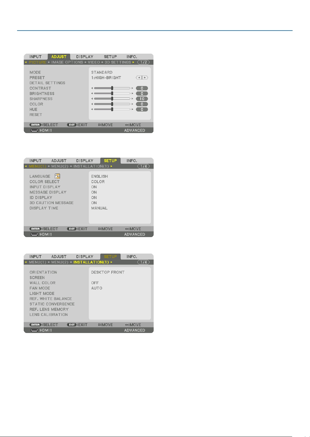
To store your adjusted values in [REF. LENS MEMORY]:
1. Press the MENU button.
The menu will be displayed.
2. Press the ▶ button to select [SETUP] and press the ENTER button.
3. Convenient Features
3. Press the ▶ button to select [INSTALLATION(1)].
54
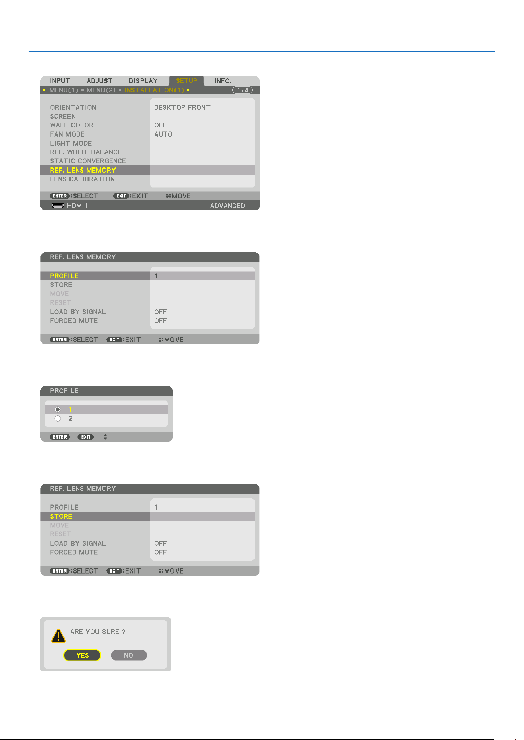
3. Convenient Features
4. Press the ▼ button to select [REF. LENS MEMORY] and press the ENTER button.
The [REF. LENS MEMORY] screen will be displayed.
5. Make sure [PROFILE] is highlighted, then press the ENTER button.
The [PROFILE] selection screen appears.
6. Press the ▼/▲ buttons to select the [PROFILE] number, then press the ENTER button.
Return to the [REF. LENS MEMORY] settings screen.
7. Select [STORE] and press the ENTER button.
The confirmation screen will be displayed.
8. Press the ◀ button to select and [YES] and press the ENTER button.
Select a [PROFILE] number and save the adjusted [LENS SHIFT], [ZOOM], and [FOCUS] values to it.
55

9. Press the MENU button.
The menu will be closed.
TIP:
• To store adjusted values for each input source, use the Lens Memory function. (→ page 97)
To call up your adjusted values from [REF. LENS MEMORY]:
1. Press the MENU button.
The menu will be displayed.
2. Press the ▶ button to select [SETUP] and press the ENTER button.
3. Convenient Features
3. Press the ▶ button to select [INSTALLATION(1)].
4. Press the ▼ button to select [REF. LENS MEMORY] and press the ENTER button.
The [REF. LENS MEMORY] screen will be displayed.
56
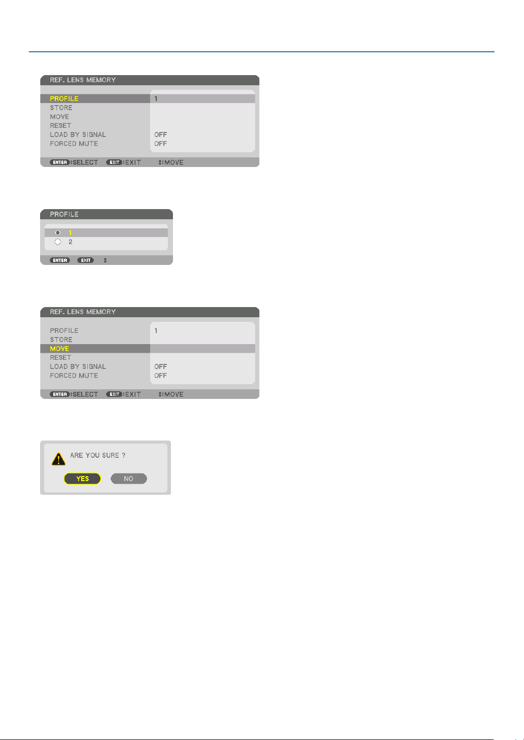
3. Convenient Features
5. Make sure [PROFILE] is highlighted, then press the ENTER button.
The [PROFILE] selection screen appears.
6. Press the ▼/▲ buttons to select the [PROFILE] number, then press the ENTER button.
Return to the [REF. LENS MEMORY] settings screen.
7. Select [MOVE] and press the ENTER button.
The lens will shift based on the adjusted values stored in the selected [PROFILE].
8. Press the ◀ button to select and [YES] and press the ENTER button.
The adjusted values will be applied to the current signal. .
9. Press the MENU button.
The menu will be closed.
57
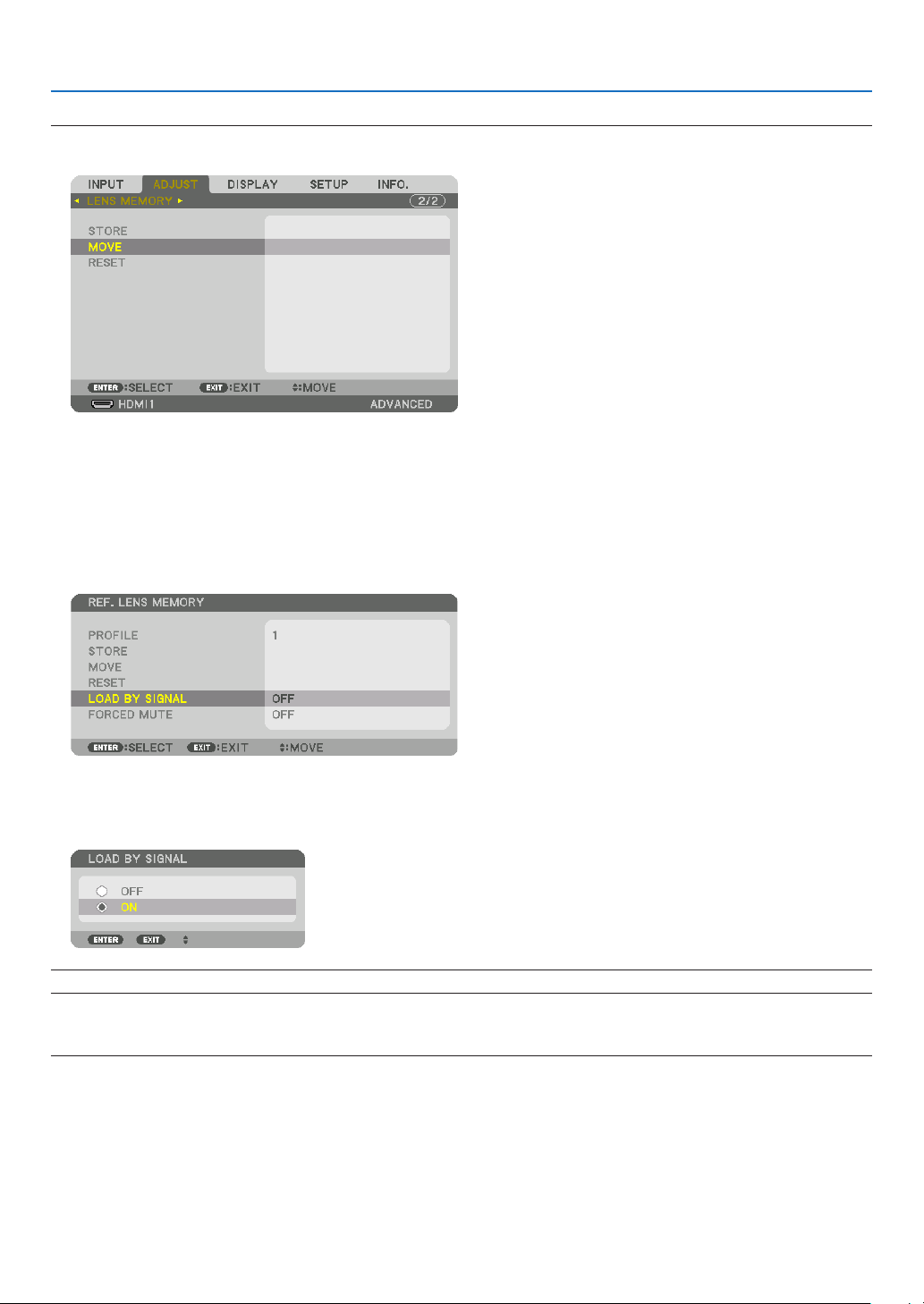
3. Convenient Features
TIP:
To call up the stored values from [LENS MEMORY]:
1. From the menu, select [ADJUST] → [LENS MEMORY] → [MOVE] and press the ENTER button.
The confirmation screen will be displayed.
2. Press the ◀ button to select and [YES] and press the ENTER button.
During projection, if the adjusted values for an input signal have been saved, the lens will shift. If not, the lens will
shift according to the adjusted values stored in the selected [REF. LENS MEMORY] [PROFILE] number.
To automatically apply the stored values at the time of source selection:
1. From the menu, select [SETUP] → [REF. LENS MEMORY] → [LOAD BY SIGNAL] and press the ENTER button.
2. Press the ▼ button to select and [ON] and press the ENTER button.
This will move the lens automatically to the position at the time of source selection according to the adjusted
values.
NOTE: The Lens Memory function may not produce a completely aligned image (due to tolerances in the lenses) using the adjusted
values stored in the projector. After calling up and applying the stored values from the Lens Memory function, finely adjust the lens
shift, zoom and focus to produce the best possible image.
58
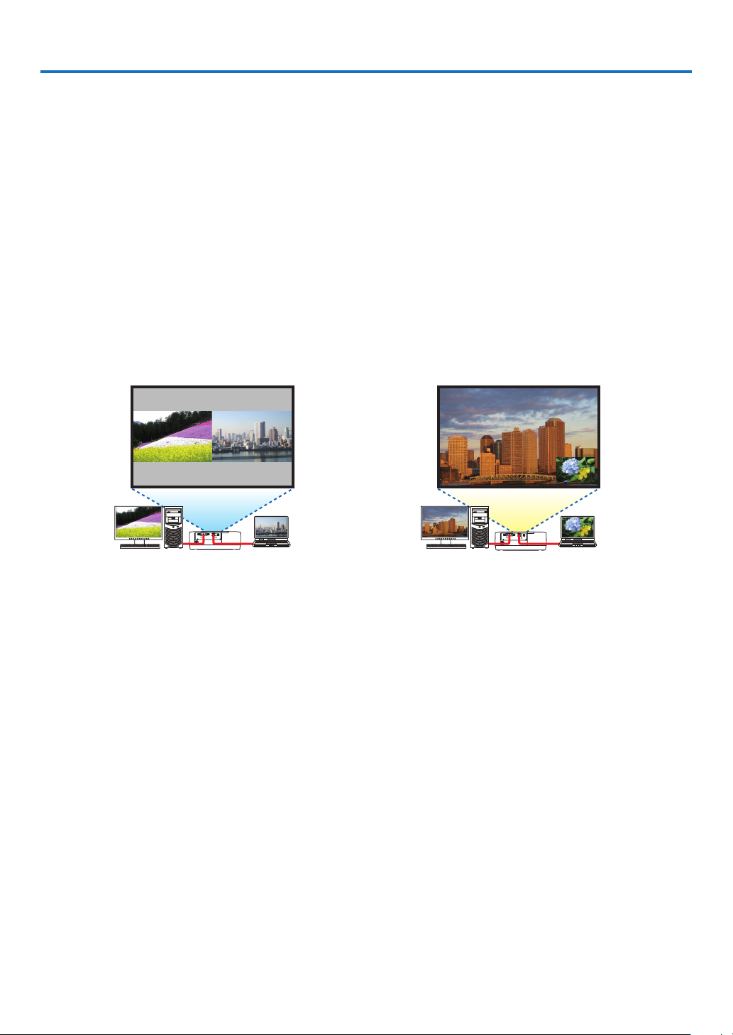
4. Multi-Screen Projection
❶ Things that can be done using multi-screen projection
This projector can be used singly or arranged in multiple units for multi-screen projection.
We will introduce an example using two projection screens here.
Case 1
Using a single projector to project two types of videos at the same time
[PIP/PICTURE BY PICTURE]
Case 2
Using four projectors to project video with a resolution of 3840 × 2160 pixels
[TILING]
Case 1. Using a single projector to project two types of videos [PIP/PICTURE BY PICTURE]
Connection example and projection image
In the case of [PICTURE BY PICTURE] In the case of [PIP]
On-screen menu operations
Display [DISPLAY] → [PIP/PICTURE BY PICTURE] → [MODE] screen in the on-screen menu and select [PIP] or
[PICTURE BY PICTURE].
For details, please refer to “4-2 Displaying Two Pictures at the Same Time”. (→ page 64)
59

4. Multi-Screen Projection
Case 2. Using four projectors to project videos with a resolution of 3840 × 2160 pixels [TILING]
Connection example and projection image
On-screen menu operations
1 Four similar videos are displayed when four projectors are projected.
Please request the retail store to adjust the projection position of each projector.
NOTE:
• When setting up the projector, assign a unique control ID to each projector.
• Set the “Color setting” and “DeepColor setting” on your Blu-ray player or computer to “Auto”. Refer to the owner’s manual accompanied with your Blu-ray player or computer for more information.
• Connect an HDMI output of your Blu-ray player or computer to the first projector and then connect to HDBaseT IN/Ethernet port
of the second and subsequent projectors.
• Selecting another input source on the second and subsequent projectors will disable the HDBaseT repeater function.
60

4. Multi-Screen Projection
2 Operate the on-screen menu using the four respective projectors to divide the image into four portions.
Display [DISPLAY] → [MULTI SCREEN] → [PICTURE SETTING] Screen in the on-screen menu and select [TIL-
ING].
(1) In the screen for setting the number of horizontal units, select [2 UNITS]. (number of units in the horizontal
direction)
(2) In the screen for setting the number of vertical units, select [2 UNITS]. (number of units in the vertical direction)
(3) In the screen for setting the horizontal order, select [1st UNIT] or [2nd UNIT].
(look at the screens, the one on the left is the [1st UNIT] while the one on the right is the [2nd UNIT])
(4) In the screen for setting the vertical order, select the [1st UNIT] or the [2nd UNIT].
(look at the screens, the one at the top is the [1st UNIT] while the one at the bottom is the [2nd UNIT])
3 Adjust the lens shift of each projector to fine-tune the boundaries of the screen.
For further fine-tuning, adjust using [DISPLAY] → [EDGE BLENDING] in the on-screen menu for each projector.
For details, please refer to “4-3 Displaying a Picture Using [EDGE BLENDING]”.
(→ page 68)
61

4. Multi-Screen Projection
Things to note when installing projectors
• Leave sufficient space on the left and right of the projector so that the intake and exhaust vents of the projector are
not obstructed. When the intake and exhaust vents are obstructed, the temperature inside the projector will rise
and this may result in a malfunction.
• Please do not pile up the projectors directly on top of one another when installing them. When the projectors are
piled up on top of one another, they may fall down, resulting in damage and failure.
The following installation is recommended when combining the installation of two projectors for multi-screen projec-
tion. Please leave sufficient space on the left and right of the projector.
Cabinet
WARNING
Please request the retail store for special installation services such as when mounting the projector to the ceiling.
Never carry out the installation by yourself. The projector may fall down and result in injury. Please use a sturdy
cabinet that can withstand the weight of the projector for the installation. Please do not pile up the projectors directly
on top of one another.
NOTE:
• For the range of the projection distance, please refer to the Appendix “Throw distance and screen size”. (→ page 152)
62

4. Multi-Screen Projection
❷ Displaying Two Pictures at the Same Time
The projector has a feature that allows you to view two different signals simultaneously. You have two modes: PIP
mode and PICTURE BY PICTURE mode.
The projection video in the rst screen display is known as the main display while the projection video that is called
out subsequently is known as the sub-display.
Select the projection function under [DISPLAY] → [PIP/PICTURE BY PICTURE] → [MODE] in the on-screen menu
(the default factory setting when shipped is PIP). (→ page 99)
• A single screen is projected when power is turned on.
Picture in Picture function
A small sub-display is displayed inside the main display.
The sub-display can be set up and adjusted as follows. (→ page 99)
• Select whether to display the sub-display at the top right, top left, bottom right
or bottom left of the screen (the size of the sub-display can be selected and
the position can be ne-tuned)
• Switch the main display with the sub-display
Picture by picture function
Display the main display and sub-display side by side.
The main display and sub-display can be set up and adjusted as follows. (→
page 100)
• Selecting the display boundary (ratio) of the main display and sub-display
• Switch the main display and sub-display
Input terminals that can be used for the main screen and sub-screen.
The main screen and sub-screen can provide the following input terminals.
• The main display and sub-display support computer signals up to WUXGA@60HzRB.
Sub-Display or additional display
Main Display
HDMI1 No Yes Yes Yes Yes
HDMI1 HDMI2 DisplayPort COMPUTER HDBaseT
HDMI2 Yes No Yes Yes Yes
DisplayPort Yes Yes No Yes Yes
COMPUTER Yes Yes Yes No Yes
HDBaseT Yes Yes Yes Yes No
Main Display
Sub-Display
Main Display Sub-Display
NOTE:
• Some signals may not appear depending on the resolution.
63

4. Multi-Screen Projection
Projecting two screens
1. Press the MENU button to display the on-screen menu and select [DISPLAY] → [PIP/PICTURE BY PICTURE].
This displays the [PIP/PICTURE BY PICTURE] screen in the on-screen menu.
2. Select [SUB INPUT] using the ▼/▲ buttons, and press the ENTER button.
This displays the [SUB INPUT] screen.
3. Select the input signal using the ▼/▲ buttons, and press the ENTER button.
* This screen belongs to a HDBaseT model.
The [PIP] (PICTURE IN PICTURE) or [PICTURE BY PICTURE] screen set up under [MODE] is projected. (→
page 99)
• When the signal name is displayed in grey, this means that it cannot be selected.
• The signal can also be selected by pressing the PIP button or PBP/POP button on the remote control.
4. Press the MENU button.
The on-screen menu will disappear.
5. When returning to single screen, display the [PIP/PICTURE BY PICTUE] screen one more time and select
[OFF] in the [SUB INPUT] screen of the Step 3.
TIP:
• During dual-screen projection, if the selected input is not supported by the sub-screen, the sub-screen will appear as a black
screen.
64

4. Multi-Screen Projection
Switching the main display with the sub-display and vice versa
1. Press the MENU button to display the on-screen menu and select [DISPLAY] → [PIP/PICTURE BY PICTURE].
This displays the [PIP/PICTURE BY PICTURE] screen in the on-screen menu.
2. Select [PICTURE SWAP] using the ▼/▲ buttons and then press the ENTER button.
Display the screen for switching the display positions.
3. Select [ON] using the ▼ button and then press the ENTER button.
The video of the main display will switch with that of the sub-display.
Sub-display video
Main display video Sub-display video
When turned “OFF” When turned “ON”
The signal output from the HDBaseT OUT/Ethernet terminal does not change even if the display positions are
switched.
4. Press the MENU button.
The on-screen menu will disappear.
Main display video
65

4. Multi-Screen Projection
Restrictions
• The following operations are enabled only for the main display.
• Audio-visual adjustments
• Video magnication / compression using the partial D-ZOOM/ZOOM +/− buttons.
However, magnication / compression is up to the positions set in [PICTURE BY PICTURE BORDER] only.
• TEST PATTERN
• The following operations are enabled for both the main display and sub-display. These operations cannot be ap-
plied individually.
• Momentary deletion of video / audio
• Video pause
• [PIP/PICTURE BY PICTURE] cannot be used when a 3D video is being displayed.
• When using the [PIP/PICTURE BY PICTURE] function, [DYNAMIC CONTRAST] can not be used.
• [PIP/PICTURE BY PICTURE] cannot be used when the signal input has a resolution of 1920 × 1200 or more.
• The HDBaseT OUT/Ethernet port has a repeater function. The output resolution is limited by the maximum resolu-
tion of the connected monitor and projector.
66

4. Multi-Screen Projection
❸ Displaying a Picture Using [EDGE BLENDING]
A high resolution video can be projected on an even bigger screen by combining multiple projectors on the left, right,
top and bottom.
This projector is equipped with an “EDGE BLENDING Function” that makes the edges (boundaries) of the projection
screen indistinguishable.
NOTE:
• For projector throw distances, refer to “Throw distance and screen size” on page 152.
• Before performing the Edge Blending function, place the projector in the correct position so that the image becomes square in
the appropriate size, and then make optical adjustments (lens shift, focus, and zoom).
• Adjust the brightness of each projector using [REF. LIGHT ADJUST] under [LIGHT MODE]. In addition, use [REF. WHITE BALANCE]
to adjust the [CONTRAST], [BRIGHTNESS] and [UNIFORMITY].
Before explaining use of the Edge Blending function
This section explains the case for “Example: Placing two projectors side by side”. As shown, the projected image on
the left is referred to as “Projector A” and the projected image on the right is referred to “Projector B”. Unless otherwise
specied hereinafter, the “projector” is used to mean both A and B.
Example: Placing two projectors side by side
Edge Blending area
Projected area
Projector A Projector B
Projected area
67
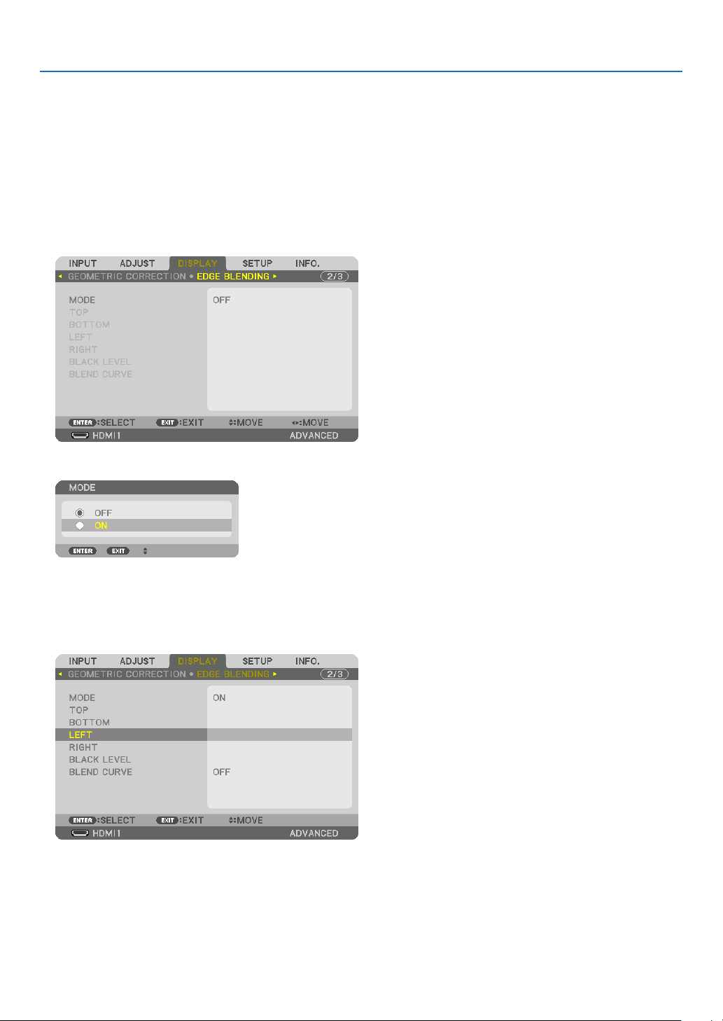
4. Multi-Screen Projection
Preparation:
• Turn on the projector and display a signal.
• When performing settings or adjustments using one remote control, enable the [CONTROL ID] for assigning ID to
each projector so as not to activate the other projectors. (→ page 121)
Setting the overlap of projection screens
① Enable [EDGE BLENDING].
1 Press the “Edge Blend.” button.
The [EDGE BLENDING] screen will be displayed. Align the cursor with [MODE] and then press the ENTER but-
ton. The mode screen will be displayed.
2 Select [MODE] → [ON] and press the ENTER button.
This enables the Edge Blending function. The following menu items are available:
[TOP], [BOTTOM], [LEFT], [RIGHT], [BLACK LEVEL], and [BLEND CURVE]
3 Select [RIGHT] for Projector A and [LEFT] for Projector B.
Press the ENTER button.
The following items are available:
[CONTROL], [MARKER], [RANGE], and [POSITION]
68

4. Multi-Screen Projection
4 Select [CONTROL] → [ON] and press the ENTER button.
Each [TOP], [BOTTOM], [LEFT], [RIGHT], and [BLACK LEVEL] has its own [CONTROL], [MARKER], [RANGE],
and [POSITION].
• For Projector A, set the [CONTROL] for the [TOP], [LEFT] and[BOTTOM] to [OFF]. Similarly for Projector B,
set the [CONTROL] for the [TOP], [RIGHT] and [BOTTOM] to [OFF].
② Adjust [RANGE] and [POSITION] to determine an area of overlapped edges of images
projected from each projector.
Turning on [MARKER] will display markers in magenta and green.
The magenta marker is used for [RANGE] and green one for [POSITION].
[RANGE]
(Determine an area of overlapped edges of
images.)
Turn on [RIGHT]
Magenta marker
[POSITION]
(Determine the position of overlapped edges of images.)
Green marker
* The 2 screens are separated in the diagram for explanatory purposes.
Turn on [LEFT]
Magenta marker
69
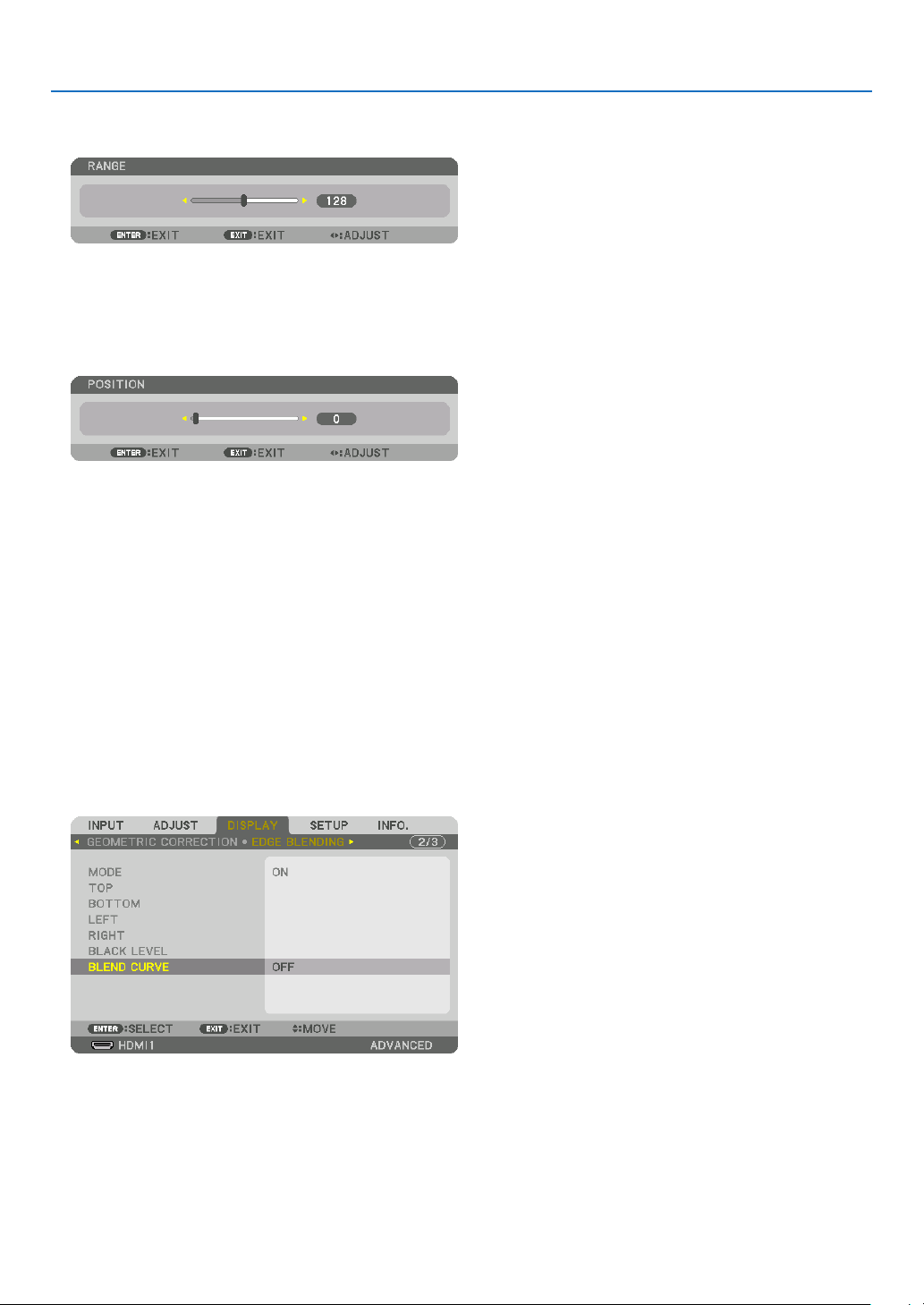
4. Multi-Screen Projection
1 Adjust [RANGE].
Use the ◀ or ▶ button to adjust the overlapped area.
TIP:
• Adjust to overlap one projector’ marker with the other projector’s marker.
2 Adjust [POSITION].
Use the ◀ or ▶ button to align one edge with the other edge of overlapped images.
TIP:
• When displaying a signal with a different resolution, perform the Edge Blending function from the start.
• Setting of [MARKER] will not be saved and return to [OFF] when the projector is turned off.
• To display or hide the marker while the projector is running, turn on or off [MARKER] from the menu.
[BLEND CURVE]
Adjust the brightness of the overlapped section on the screens. According to the necessity, adjust the brightness of
the overlapped section on the screens by the [BLEND CURVE] AND [BLACK LEVEL].
• Set the [MODE] to [ON] for selecting [BLEND CURVE] and [BLACK LEVEL].
Selecting an option for the [BLEND CURVE]
By controlling the graduation of the overlapped section on the screens, it makes the border on the projected screens
inconspicuous. Select the optimal option among nine.
1. On the On-Screen Menu, move the cursor onto the [DISPLAY] → [EDGE BLENDING] → [BLEND CURVE] and
then press the ENTER. The option setting screen for the [BREND CURVE] is displayed on.
70

4. Multi-Screen Projection
2. Select one option among nine by ▲ or ▼.
Black Level Adjustment
This adjusts the black level of the overlapping area and the non-overlapping area of the multi-screen (EDGE BLENDING).
Adjust the brightness level if you feel the difference is too large.
NOTE:
This function is enabled only when [MODE] is turned on.
Adjustable area varies depending on what combination of [TOP], [BOTTOM], [LEFT] and [RIGHT] are turned on.
Example: Adjusting the Black Level when placing two projectors side by side
Width of overlap
Adjust [CENTER] Adjust [CENTER]
Projector A’s
image
Adjust [CENTER-RIGHT] Adjust [CENTER-LEFT]
Projector B’s
image
1. Select [DISPLAY] → [EDGE BLENDING] → [BLACK LEVEL] and press the ENTER button.
The screen will switch to the black level adjustment screen.
71
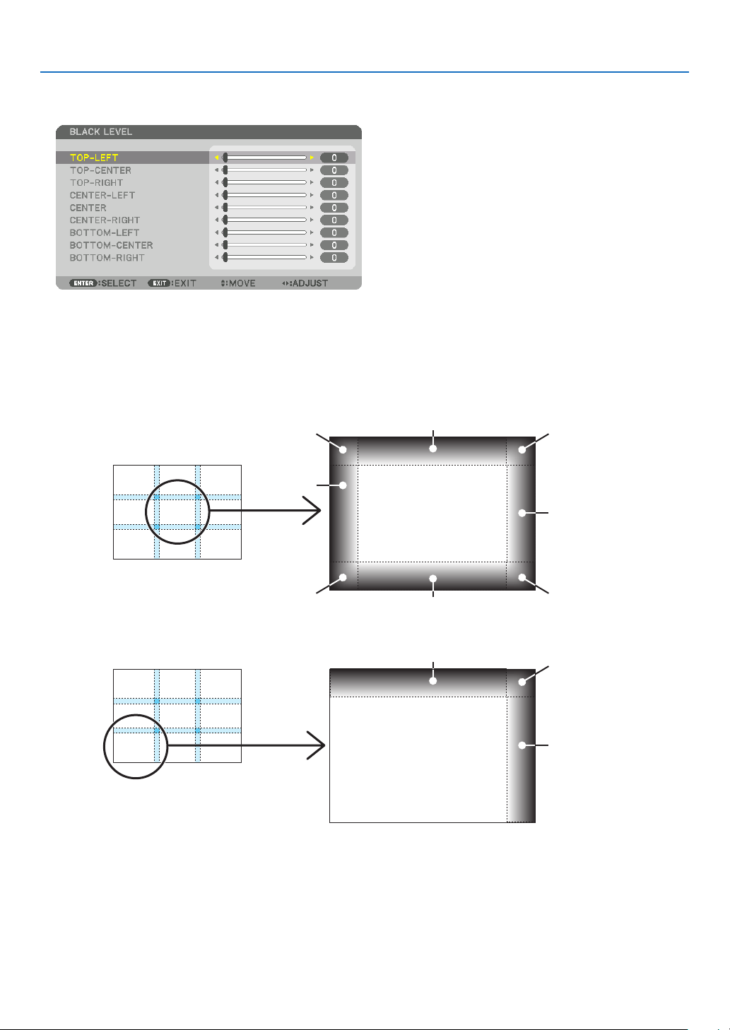
4. Multi-Screen Projection
2. Use the ▼ or ▲ button to select an item and use the ◀ or ▶ to adjust the black level.
Do this for the other projector if necessary.
9-segmented portions for Black Level adjustment
The center projector
This function adjusts the brightness level of 9-segmented portions for the center projector and 4-segmented portions
for the left bottom projector as shown below.
TOP-LEFT
CENTER-
LEFT
BOTTOM-LEFT
TOP-CENTER
CENTER
BOTTOM-CENTER
TOP-CENTER
CENTER
TOP-RIGHT
CENTER-RIGHT
BOTTOM-RIGHT
TOP-RIGHT
CENTER-RIGHT
TIP:
• The number of black level division screens (maximum of nine divisions) changes depending on the number of edge blending
positions selected (top, bottom, right, left). In addition, when the top / bottom and left / right ends are selected, the corner division
screen appears.
• The edge blending width is the width set in the range and the corner is formed by the intersecting area of the top / bottom ends
or left / right ends.
• The [BLACK LEVEL] can be adjusted to make it brighter only.
72
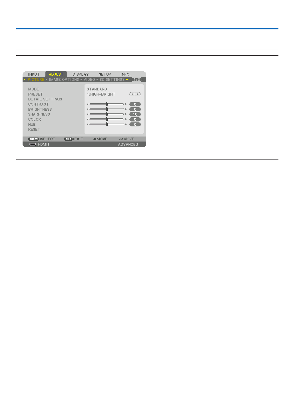
5. Using On-Screen Menu
❶ Using the Menus
NOTE: The on-screen menu may not be displayed correctly while interlaced motion video image is projected.
1. Press the MENU button on the remote control or the projector cabinet to display the menu.
NOTE: The commands such as ENTER, EXIT, ▲▼, ◀▶ in the bottom show available buttons for your operation.
2. Press the ◀▶ buttons on the remote control or the projector cabinet to display the submenu.
3. Press the ENTER button on the remote control or the projector cabinet to highlight the top item or the first
tab.
4. Use the ▲▼ buttons on the remote control or the projector cabinet to select the item you want to adjust or
set.
You can use the ◀▶ buttons on the remote control or the projector cabinet to select the tab you want.
5. Press the ENTER button on the remote control or the projector cabinet to display the submenu window.
6. Adjust the level or turn the selected item on or off by using the ▲▼◀▶ buttons on the remote control or the
projector cabinet.
Changes are stored until adjusted again.
7. Repeat steps 2-6 to adjust an additional item, or press the EXIT button on the remote control or the projector
cabinet to quit the menu display.
NOTE: When a menu or message is displayed, several lines of information may be lost, depending on the signal or settings.
8. Press the MENU button to close the menu.
To return to the previous menu, press the EXIT button.
73
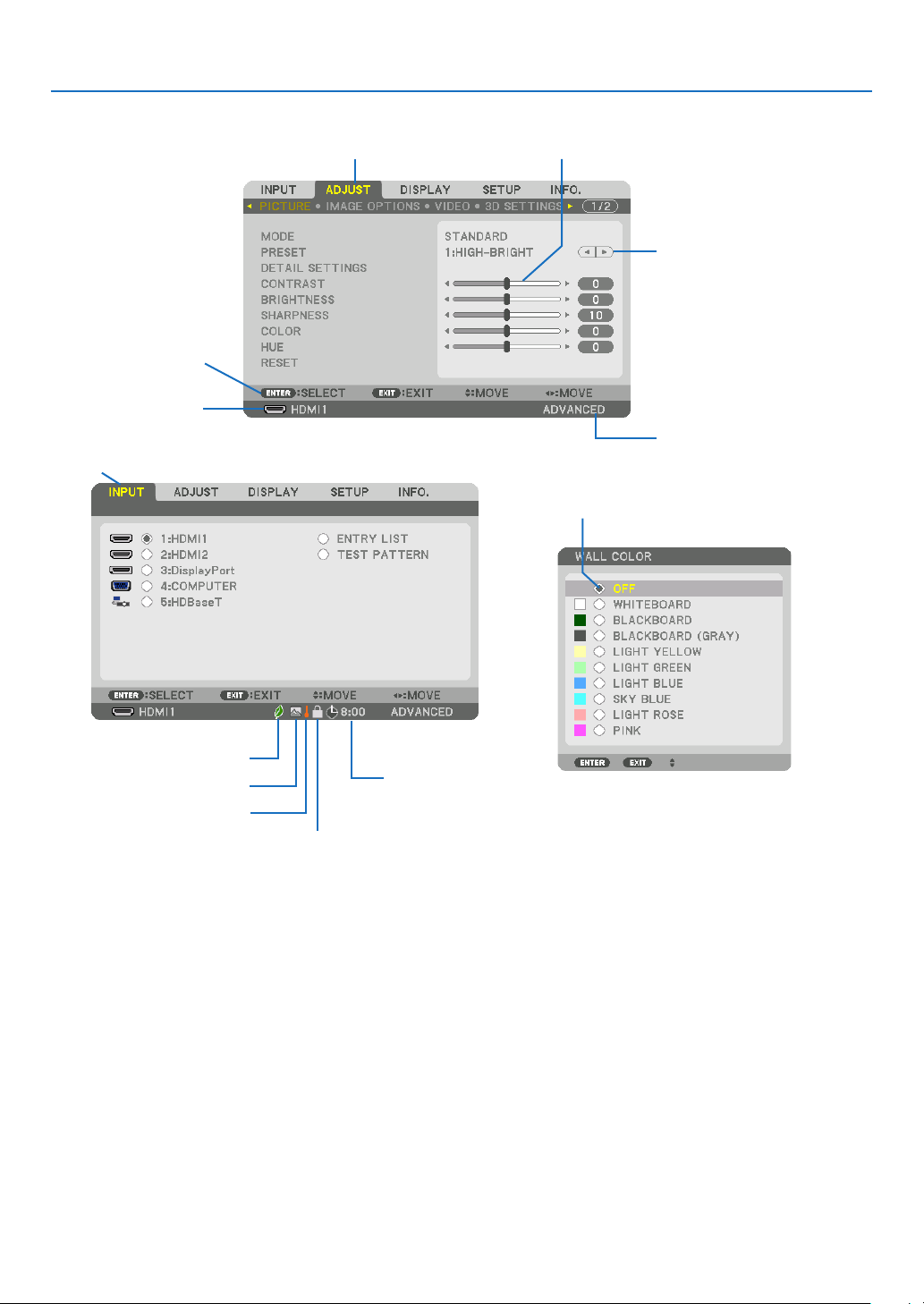
❷
Menu Elements
Available buttons
Source
Highlight
Ta b
5. Using On-Screen Menu
Slide bar
Solid triangle
Menu mode
Radio button
LIGHT MODE symbol
High Altitude symbol
Thermometer symbol
Key Lock symbol
Menu windows or dialog boxes typically have the following elements:
Highlight ����������������������������� Indicates the selected menu or item�
Solid triangle ����������������������Indicates further choices are available� A highlighted triangle indicates the item is active�
Tab �������������������������������������� Indicates a group of features in a dialog box� Selecting on any tab brings its page to the front�
Radio button ����������������������� Use this round button to select an option in a dialog box�
Source ��������������������������������Indicates the currently selected source�
Menu mode ������������������������Indicates the current menu mode: BASIC or ADVANCED�
Off Timer remaining time ���� Indicates the remaining countdown time when the [OFF TIMER] is preset�
Slide bar �����������������������������Indicates settings or the direction of adjustment�
LIGHT MODE symbol ���������� Indicates [LIGHT MODE] is set�
Key Lock symbol ����������������Indicates the [CONTROL PANEL LOCK] is enabled�
Thermometer symbol ���������Indicates the [LIGHT MODE] is forcibly set to [ON] mode because the internal temperature is too
high�
High Altitude symbol ����������Indicates the [FAN MODE] is set to [HIGH ALTITUDE] mode�
Off Timer remaining
time
74
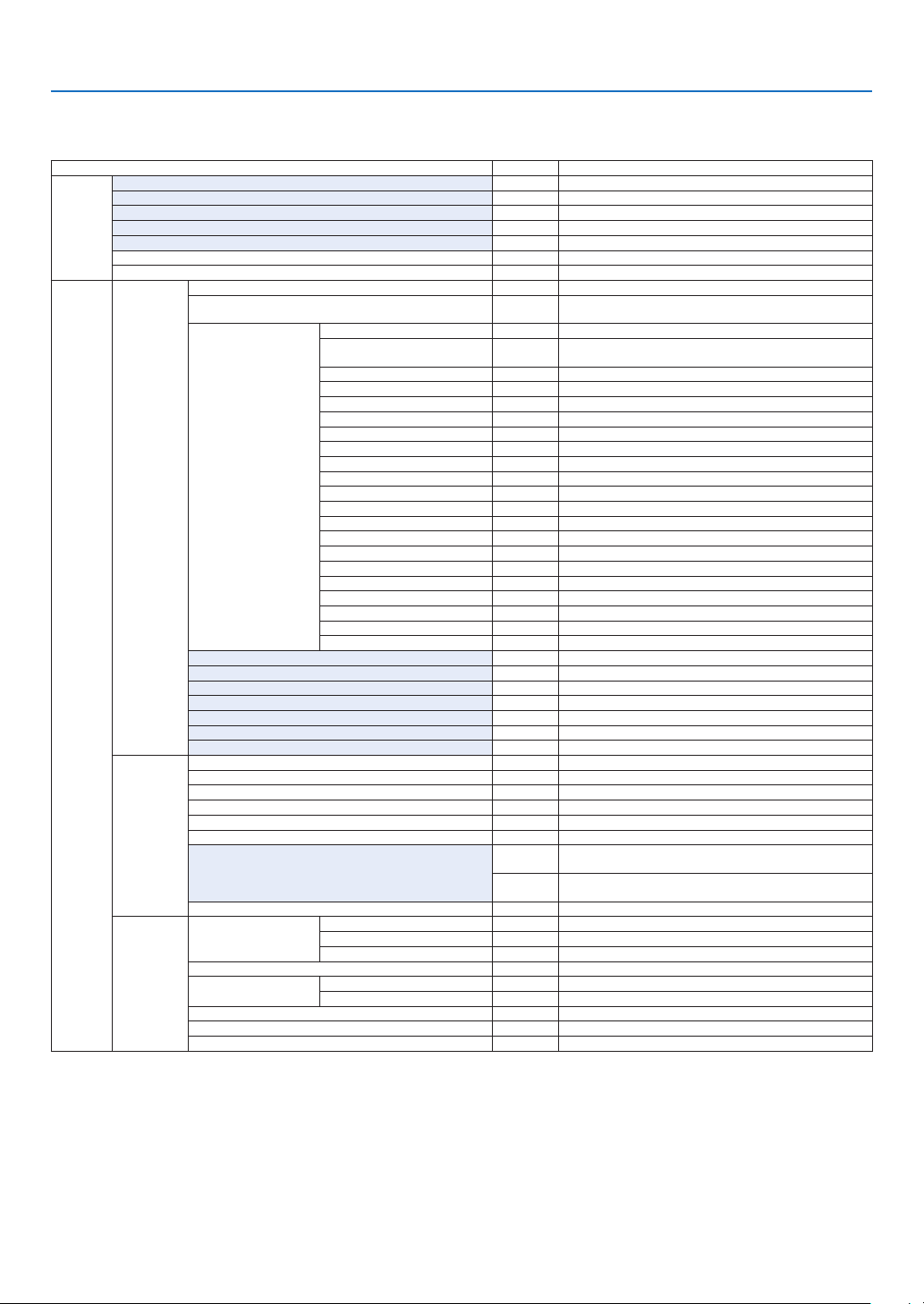
5. Using On-Screen Menu
❸ List of Menu Items
• Basic menu items are indicated by shaded area.
Some menu items are not available depending on the input source.
Menu Item Default Options
INPUT
ADJUST
1:HDMI1 *
2:HDMI2 *
3:DisplayPort *
4:COMPUTER *
5:HDBaseT
ENTRY LIST
TEST PATTERN
PICTURE
IMAGE
OPTIONS
VIDEO
MODE STANDARD STANDARD, PROFESSIONAL
PRESET *
GENERAL
REFERENCE *
GAMMA CORRECTION*
SCREEN SIZE*
COLOR TEMPERATURE*
DYNAMIC CONTRAST * OFF, MOTION IMAGE, STILL IMAGE
LIGHT ADJUST *
WHITE BALANCE
CONTRAST R 0
DETAIL SETTINGS
CONTRAST 50
BRIGHTNESS 50
SHARPNESS 10
COLOR 50
HUE 0
VOLUME
RESET
CLOCK *
PHASE *
HORIZONTAL *
VERTICAL *
BLANKING * TOP, BOTTOM, LEFT, RIGHT
OVERSCAN AUTO, 0[%], 5[%], 10[%]
ASPECT RATIO
INPUT RESOLUTION*
NOISE REDUCTION
DEINTERLACE NORMAL NORMAL, MOVIE, STILL
CONTRAST
ENHANCEMENT
SIGNAL TYPE AUTO AUTO, RGB, REC601, REC709, REC2020
VIDEO LEVEL AUTO AUTO, NORMAL, ENHANCED, SUPER WHITE
HDR MODE*
5
CONTRAST G 0
CONTRAST B 0
BRIGHTNESS R 0
BRIGHTNESS G 0
BRIGHTNESS B 0
COLOR CORRECTION
RED 0 HUE, SATURATION
GREEN 0 HUE, SATURATION
BLUE 0 HUE, SATURATION
YELLOW 0 HUE, SATURATION
MAGENTA 0 HUE, SATURATION
CYAN 0 HUE, SATURATION
4
RANDOM NR * OFF, LOW, MEDIUM, HIGH
MOSQUITO NR OFF OFF, LOW, MEDIUM, HIGH
BLOCK NR OFF OFF, LOW, MEDIUM, HIGH
MODE AUTO OFF, AUTO, NORMAL
GAIN
1
2
3
AUTO
AUTO
AUTO AUTO, OFF, ON
AUTO, 1:HIGH-BRIGHT, 2:PRESENTATION, 3:VIDEO, 4:MOVIE,
5:GRAPHIC, 6:sRGB, 7:DICOM SIM�
HIGH-BRIGHT, PRESENTATION, VIDEO, MOVIE, GRAPHIC, sRGB,
DICOM SIM�
DYNAMIC, NATURAL, BLACK DETAIL
* LARGE, MEDIUM, SMALL
*
(HDTV/SDTV) AUTO, NORMAL, 4:3, LETTERBOX, WIDE SCREEN,
ZOOM, FULL
(COMPUTER) AUTO, NORMAL, 4:3, 5:4, 16:9, 15:9, 16:10, FULL,
NATIVE
* –
* The asterisk (*) indicates that the default setting varies depending on the signal.
*1 The [GAMMA CORRECTION] item is available when an item other than [DICOM SIM.] is selected for [REFERENCE].
*2 The [SCREEN SIZE] item is available when [DICOM SIM.] is selected for [REFERENCE].
*3 When [HIGH-BRIGHT] is selected in [REFERENCE], the [COLOR TEMPERATURE] is not available.
*4 The [INPUT RESOLUTION] item can be selected for COMPUTER input.
*5 The [HDR MODE] item is available exclusively for 4K signal.
75

5. Using On-Screen Menu
Menu Item Default Options
3D SETTINGS
ADJUST
LENS
MEMORY
PIP/PICTURE
BY PICTURE
GEOMETRIC
CORRECTION
DISPLAY
EDGE
BLENDING
STEREO VIEWER SINGLE SINGLE, DUAL LEFT, DUAL RIGHT
STEREO FILTER SINGLE SINGLE, DUAL LEFT, DUAL RIGHT
FORMAT AUTO
L/R INVERT OFF OFF, ON
STORE
MOVE
RESET
SUB INPUT OFF OFF, HDMI1, HDMI2, DisplayPort, COMPUTER, HDBaseT
MODE PIP PIP, PICTURE BY PICTURE
PICTURE SWAP OFF OFF, ON
PIP SETTING
BORDER
MODE OFF
KEYSTONE
CORNERSTONE
HORIZONTAL CORNER
VERTICAL CORNER
WARP
PC TOOL OFF OFF, 1, 2, 3
RESET
MODE OFF OFF, ON
TOP
BOTTOM
LEFT
RIGHT
BLACK LEVEL
BLEND CURVE 5 OFF, 1, 2, 3, 4, 5, 6, 7, 8, 9
START POSITION TOP-LEFT TOP-LEFT, TOP-RIGHT, BOTTOM-LEFT, BOTTOM-RIGHT
HORIZONTAL POSITION
VERTICAL POSITION
SIZE MEDIUM LARGE, MEDIUM, SMALL
HORIZONTAL
VERTICAL
TILT
THROW RATIO
CONTROL ON OFF, ON
MARKER OFF OFF, ON
RANGE
POSITION
CONTROL ON OFF, ON
MARKER OFF OFF, ON
RANGE
POSITION
CONTROL ON OFF, ON
MARKER OFF OFF, ON
RANGE
POSITION
CONTROL ON OFF, ON
MARKER OFF OFF, ON
RANGE
POSITION
TOP-LEFT
TOP-CENTER
TOP-RIGHT
CENTER-LEFT
CENTER
CENTER-RIGHT
BOTTOM-LEFT
BOTTOM-CENTER
BOTTOM-RIGHT
AUTO, OFF(2D), FRAME PACKING, SIDE BY SIDE(HALF), SIDE
BY SIDE(FULL), TOP AND BOTTOM, FRAME ALTERNATIVE, LINE
ALTERNATIVE
OFF, KEYSTONE, CORNERSTONE, HORIZONTAL CORNER,
VERTICAL CORNER, WARP, PC TOOL
TOP-LEFT, TOP, TOP-RIGHT, LEFT, RIGHT, BOTTOM-LEFT,
BOTTOM, BOTTOM-RIGHT
TOP-LEFT, TOP, TOP-RIGHT, LEFT, RIGHT, BOTTOM-LEFT,
BOTTOM, BOTTOM-RIGHT
TOP-LEFT, TOP, TOP-RIGHT, LEFT, RIGHT, BOTTOM-LEFT,
BOTTOM, BOTTOM-RIGHT
TOP-LEFT, TOP, TOP-RIGHT, LEFT, RIGHT, BOTTOM-LEFT,
BOTTOM, BOTTOM-RIGHT
76

5. Using On-Screen Menu
Menu Item Default Options
WHITE BALANCE
DISPLAY
SETUP
MULTI
SCREEN
MENU(1)
MENU(2)
INSTALLATION(1)
PICTURE SETTING
LANGUAGE ENGLISH
COLOR SELECT COLOR COLOR, MONOCHROME
INPUT DISPLAY ON OFF, ON
MESSAGE DISPLAY ON OFF, ON
ID DISPLAY ON OFF, ON
3D CAUTION MESSAGE ON OFF, ON
DISPLAY TIME
MENU ANGLE 0°, 90°, 270°
MENU POSITION
ORIENTATION AUTO
SCREEN
WALL COLOR OFF
FAN MODE AUTO AUTO, NORMAL, HIGH, HIGH ALTITUDE
LIGHT MODE
REF� WHITE BALANCE
STATIC CONVERGENCE
REF� LENS MEMORY
LENS CALIBRATION
MODE OFF OFF, ON
CONTRAST W
CONTRAST R
CONTRAST G
CONTRAST B
BRIGHTNESS W
BRIGHTNESS R
BRIGHTNESS G
BRIGHTNESS B
MODE OFF OFF, ZOOM, TILING
ZOOM
TILING
HORIZONTAL POSITION
VERTICAL POSITION
RESET
SCREEN TYPE FREE FREE, 4:3 SCREEN, 16:9 SCREEN, 16:10 SCREEN
POSITION
LIGHT MODE ECO1 NORMAL, ECO1, ECO2, LONG LIFE
CONSTANT BRIGHTNESS OFF OFF, ON
REF� LIGHT ADJUST
CONTRAST R
CONTRAST G
CONTRAST B
BRIGHTNESS R
BRIGHTNESS G
BRIGHTNESS B
UNIFORMITY R
UNIFORMITY B
HORIZONTAL R
HORIZONTAL G
HORIZONTAL B
VERTICAL R
VERTICAL G
VERTICAL B
PROFILE 1 1, 2
STORE
MOVE
RESET
LOAD BY SIGNAL OFF OFF, ON
FORCED MUTE OFF OFF, ON
HORIZONTAL ZOOM
VERTICAL ZOOM
HORIZONTAL
POSITION
VERTICAL POSITION
WIDTH 1 UNIT, 2 UNITS, 3 UNITS, 4 UNITS
HEIGHT 1 UNIT, 2 UNITS, 3 UNITS, 4 UNITS
HORIZONTAL
POSITION
VERTICAL POSITION 1st UNIT, 2nd UNIT, 3rd UNIT, 4th UNIT
AUTO 45
1st UNIT, 2nd UNIT, 3rd UNIT, 4th UNIT
ENGLISH, DEUTSCH, FRANÇAIS, ITALIANO, ESPAÑOL, SVENSKA,
日本語
DANSK, PORTUGUÊS, ČEŠTINA, MAGYAR, POLSKI,
NEDERLANDS, SUOMI
NORSK, TÜRKÇE, РУССКИЙ,
ROMÂNĂ, HRVATSKA, БЪЛГАРСКИ, INDONESIA, , ไทย,
, 繁體中文, Tiếng Việt
MANUAL, AUTO 5 SEC, AUTO 15 SEC, AUTO 45 SEC
SEC
AUTO, DESKTOP FRONT, CEILING REAR, DESKTOP REAR,
CEILING FRONT
OFF, WHITEBOARD, BLACKBOARD, BLACKBOARD (GRAY), LIGHT
YELLOW, LIGHT GREEN, LIGHT BLUE, SKY BLUE, LIGHT ROSE,
PINK
, Ελληνικά, 简体中文, 한국어
77

5. Using On-Screen Menu
Menu Item Default Options
SETUP
INSTALLATION(2)
CONTROL
SHUTTER SETTINGS
ADMINISTRATOR MODE
PROGRAM
TIMER
TOOLS
DATE AND TIME
SETTINGS
MOUSE
CONTROL PANEL LOCK OFF OFF, ON
SECURITY OFF OFF, ON
COMMUNICATION SPEED 38400bps 4800bps, 9600bps, 19200bps, 38400bps, 115200bps
CONTROL ID
REMOTE SENSOR
POWER ON SHUTTER OPEN OPEN, CLOSE
FADE IN TIME 0–10 SEC
FADE OUT TIME 0–10 SEC
MENU MODE ADVANCED ADVANCED, BASIC
NOT SAVE SETTING VALUES OFF OFF, ON
NEW PASSWORD
CONFIRM PASSWORD
ENABLE OFF OFF, ON
SETTINGS
TIME
ZONE
SETTIMGS
DATE
AND TIME
SETTINGS
SUMMER
TIME
SETTINGS
BUTTON RIGHT HAND RIGHT HAND, LEFT HAND
SENSITIVITY MEDIUM FAST, MEDIUM, SLOW
CONTROL ID NUMBER 1 1–254
CONTROL ID OFF OFF, ON, AUTO
ACTIVE OFF OFF, ON
DAY SUN
TIME
FUNCTION POWER POWER, INPUT, LIGHT MODE
EDIT
ADVANCED
SETTINGS
POWER OFF OFF, ON
INPUT HDMI1 HDMI1, HDMI2, DisplayPort, COMPUTER, HDBaseT
LIGHT MODE ECO1 NORMAL, ECO1, ECO2, LONG LIFE
REPEAT OFF OFF, ON
DELETE
UP
DOWN
BACK
UTC
DATE MM/DD/YYYY
TIME HH:MM
INTERNET TIME
SERVER
IP ADDRESS
UPDATE
ENABLE OFF, ON
MON(START) 1, 2, 3, 4, 5, 6, 7, 8, 9, 10, 11, 12
DAY(START)
TIME(START)
MON(EXIT) 1, 2, 3, 4, 5, 6, 7, 8, 9, 10, 11, 12
DAY(EXIT)
TIME(EXIT)
TIME DIFFERENCE +01:00, +00:30, -00:30, -01:00
SUN, MON, TUE, WED, THU, FRI, SAT, MON-FRI, MON-SAT,
EVERY DAY
-12:00, -11:30, -11:00, -10:30, -10:00, -09:30, -09:00, -08:30,
-08:00, -07:30, -07:00, -06:30, -06:00, -05:30, -05:00, -04:30,
-04:00, -03:30, -03:00, -02:30, -02:00, -01:30, -01:00, -00:30,
00:00, +00:30, +01:00, +01:30, +02:00, +02:30, +03:00, +03:30,
+04:00, +04;30, +05:00, +05:30, +06:00, +06:30, +07:00, +07:30,
+08:00, +08:30, +09:00, +09:30, +10:00, +10:30, +11:00, +11:30,
+12:00, +12:30, +13:00
OFF, ON
FIRST WEEK, SECOND WEEK, THIRD WEEK, FOURTH WEEK, LAST
WEEK
SUN, MON, TUE, WED, THU, FRI, SAT
FIRST WEEK, SECOND WEEK, THIRD WEEK, FOURTH WEEK, LAST
WEEK
SUN, MON, TUE, WED, THU, FRI, SAT
FRONT/
FRONT/BACK, FRONT, BACK, HDBaseT
BACK
78

5. Using On-Screen Menu
Menu Item Default Options
WIRED LAN
PROJECTOR NAME PROJECTOR NAME PJ-********
DOMAIN
NETWORK
SETUP
SETTINGS
SOURCE
OPTIONS
POWER
OPTIONS
RESET
ALERT MAIL
NETWORK SERVICE
AUTO ADJUST NORMAL OFF, NORMAL, FINE
AUDIO SELECT
DEFAULT INPUT SELECT LAST LAST, AUTO, HDMI1, HDMI2, DisplayPort, COMPUTER, HDBaseT
SEAMLESS SWITCHING OFF OFF, ON
BACKGROUND BLUE BLUE, BLACK, LOGO
HDBaseT OUT SELECT AUTO AUTO, HDMI1, HDMI2, DisplayPort, HDBaseT
EDID VERSION
HDCP VERSION
STANDBY MODE NORMAL NORMAL, SLEEP
DIRECT POWER ON OFF OFF, ON
AUTO POWER ON SELECT OFF OFF, HDMI1, HDMI2, DisplayPort, COMPUTER, HDBaseT
AUTO POWER OFF 0:15 OFF, 0:05, 0:10, 0:15, 0:20, 0:30, 1:00
OFF TIMER OFF OFF, 0:30, 1:00, 2:00, 4:00, 8:00, 12:00, 16:00
CURRENT SIGNAL
ALL DATA
ALL DATA (INCLUDING ENTRY LIST)
INTERFACE LAN, HDBaseT
PROFILES DISABLE, PROFILE 1, PROFILE 2
DHCP OFF, ON
IP ADDRESS
SUBNET MASK
GATEWAY
AUTO DNS OFF, ON
DNS CONFIGURATION
RECONNECT
HOST NAME pj-********
DOMAIN NAME
ALERT MAIL OFF, ON
HOST NAME pj-********
DOMAIN NAME
SENDER'S ADDRESS
SMTP SERVER NAME
RECIPIENT'S ADDRESS 1
RECIPIENT'S ADDRESS 2
RECIPIENT'S ADDRESS 3
TEST MAIL
HTTP
SERVER
PJLink
AMX BEACON OFF, ON
CRESTRON
Extron XTP OFF, ON
HDMI1 HDMI1 HDMI1, COMPUTER
HDMI2 HDMI2 HDMI2, COMPUTER
DisplayPort DisplayPort DisplayPort, COMPUTER
HDBaseT HDBaseT HDBaseT, COMPUTER
HDMI1 MODE1 MODE1, MODE2
HDMI2 MODE1 MODE1, MODE2
HDMI1
HDMI2 HDCP2�2 HDCP2�2, HDCP1�4
HDBaseT HDCP1�4 HDCP2�2, HDCP1�4
NEW PASSWORD
CONFIRM PASSWORD
NEW PASSWORD
CONFIRM PASSWORD
ROOMVIEW
CRESTRON
CONTROL
ENABLE
IP
ADDRESS
IP ID
HDCP2�2 HDCP2�2, HDCP1�4
79

5. Using On-Screen Menu
Menu Item Default Options
USAGE TIME
SOURCE(1)
SOURCE(2)
SOURCE(3)
INFO�
SOURCE(4)
WIRED LAN
VERSION(1)
OTHERS
CONDITIONS
HDBaseT
LIGHT HOURS USED
TOTAL CARBON SAVINGS
INPUT TERMINAL
RESOLUTION
HORIZONTAL FREQUENCY
VERTICAL FREQUENCY
SYNC TYPE
SYNC POLARITY
SCAN TYPE
SOURCE NAME
ENTRY NO�
SIGNAL TYPE
BIT DEPTH
VIDEO LEVEL
SAMPLING FREQUENCY
3D FORMAT
INPUT TERMINAL
RESOLUTION
HORIZONTAL FREQUENCY
VERTICAL FREQUENCY
SYNC TYPE
SYNC POLARITY
SCAN TYPE
SOURCE NAME
ENTRY NO�
SIGNAL TYPE
BIT DEPTH
VIDEO LEVEL
SAMPLING FREQUENCY
3D FORMAT
IP ADDRESS
SUBNET MASK
GATEWAY
MAC ADDRESS
FIRMWARE
DATA
FIRMWARE2
DATE TIME
PROJECTOR NAME
MODEL NO�
SERIAL NUMBER
CONTROL ID*
DETECTED PROJECTORS
LENS ID
INTAKE TEMPERATURE
EXHAUST TEMPERATURE
ATMOSPHERIC PRESSURE
INSTALLATION POSITION
X-AXIS
Y-AXIS
Z-AXIS
SIGNAL QUALITY
OPERATION MODE
LINK STATUS
HDMI STATUS
5
*5 [CONTROL ID] will be displayed when [CONTROL ID] has been set up.
80
 Loading...