


POWERMATE P
Electronic User’s Guide

Table of Contents
Starting Up Your Computer for the First Time 6
Setting Up Your Operating System 20
Getting to Know Your Computer 23
Communicating With Your Computer 40
Applications 42
Introducing BIOS Setup for Windows Vista
Recovery Information for Windows Vista
Frequently Asked Questions (FAQ) 77
Setting Up a Healthy Work Environment 85
Safety Notices
Glossary
License Agreement
Copyright
Trademarks
Official Name of the Software Used
®
70
®
only 72
91
101
102
104
105
106
- 2 -

About Your Electronic User’s Guide
The illustrations, colours and pictures shown are for descriptive purposes. They may vary
slightly from country to country and the unit you purchase. Please refer to the finished product
for final configurations. Specifications and model names are subject to change without notice.
Text Setup
To make this document as easy to use as possible, additional texts will appear throughout. The
following details the layout and meaning of these additional texts.
Note
Notes give particularly important information about an item being described.
CAUTION
Cautions indicate situations that can damage the computer hardware or software.
WARNING
Warnings alert you to situations that could result in serious personal injury or even
loss of life.
* *For specific models only
Items marked with an asterisk (*) denotes optional items only supplied for specific
models. If the items are not found in the packaging box, it means that they are not
applicable to the system you have just purchased, hence they are not included for
you in the system.
Electronic User’s Guide
To help you familiarise yourself with your new system, we have preinstalled an “Electronic
User’s Guide” for you inside the system (for specific models only, and only applicable to the
Windows
Windows
Visit our website at www.nec-computers-ap.com regularly to download the most up-to-date
Electronic User’s Guide and print it for your reference.
Print in small booklets using recycled paper. Make two-sided prints and copies using the
“duplex” function, print multiple images/page per page, and print only the quantity you need
at the time you need it. This gives you a handy way to store the booklet nearby and saves
paper.
®
operating system). This guide will contain more information on your system and
®
.
Note
We recommend that you print this documentation. It will then be easily accessible
even when your system is shut down. To print the Electronic User’s Guide, click
“File” on the top menubar, and then click “Print” from the dropdown menu. You must
have a printer installed and connected to be able to print.
- 3 -
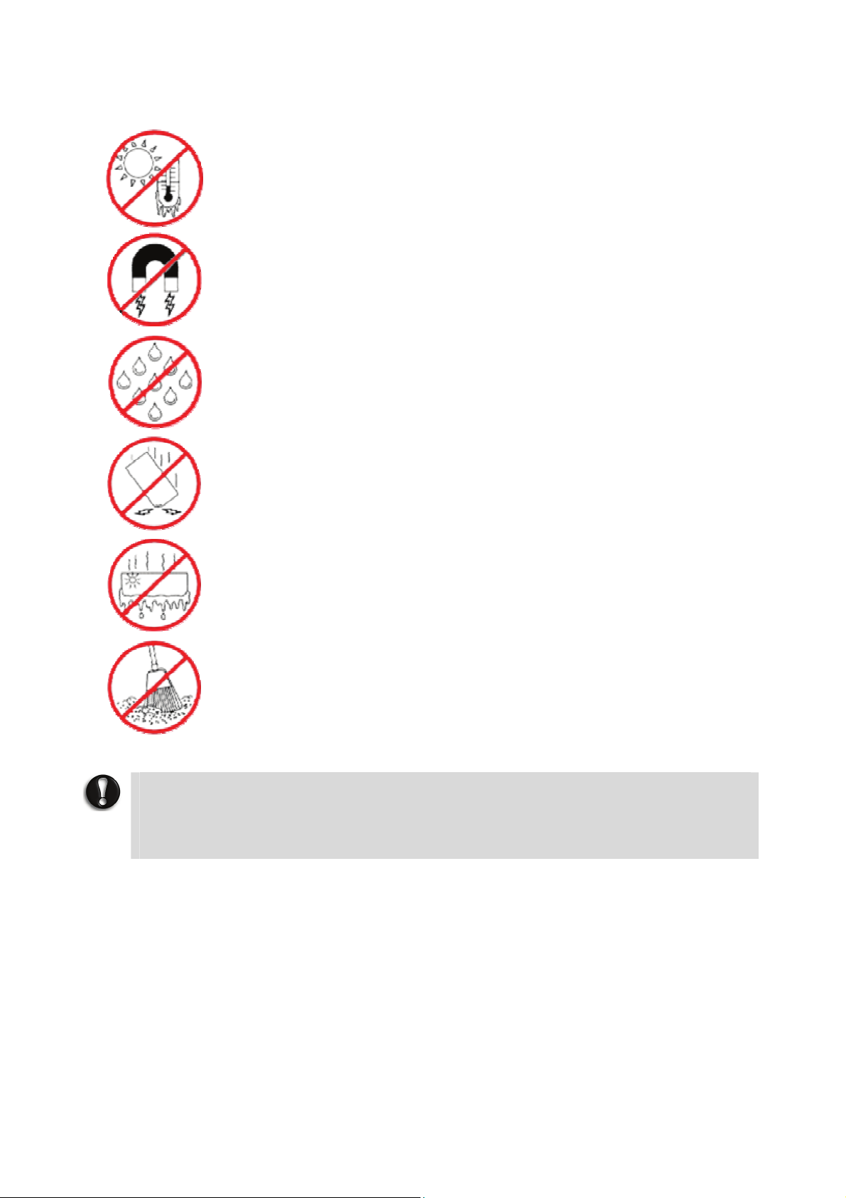
Basic Care and Handling Tips
Protect the computer from extremely low or high
temperatures. Let the computer warm (or cool) to room
temperature before using it.
Keep the computer away from magnetised areas (some airline
tray tables are magnetic; do not set your computer on top of
them). Doing so may damage the data on your hard drive.
Keep the computer dry.
Do not wipe the computer with a wet cloth or pour fluid onto
it.
Protect the computer from strong physical contact, such as
being bumped or dropped.
Check the computer for condensation.
If condensation is present, allow it to evaporate before
switching on the computer.
Keep the computer away from dust, sand and dirt.
CAUTION
Immediately turn off and unplug the computer under the following conditions:
• The power cord has been damaged or frayed.
• Liquid has spilled on or into the computer.
• The computer has been dropped or its casing has been damaged.
- 4 -

Storage Requirements
Store the computer and AC adaptor in an environment that meets the following
conditions:
Should the temperature of the computer suddenly rise or fall (for example, when you move
the computer from a cold place to a warm place), vapour may condense inside the computer.
Turning on the computer under such conditions can damage the internal computer
components.
Before turning on the computer, wait until the computer's internal temperature stabilises with
the new environment and any internal moisture has evaporated.
• Operate and store your computer within the recommended temperatures and humidity
levels (refer to the section on “Product Storage Environment Guidelines” for more
information).
• Keep the storage area free from vibration and magnetic fields.
• Keep the computer and its components away from organic solvents or corrosive gases.
• Avoid leaving the computer and its components under direct sunlight or near heat
sources.
- 5 -
Starting Up Your Computer for the First Time
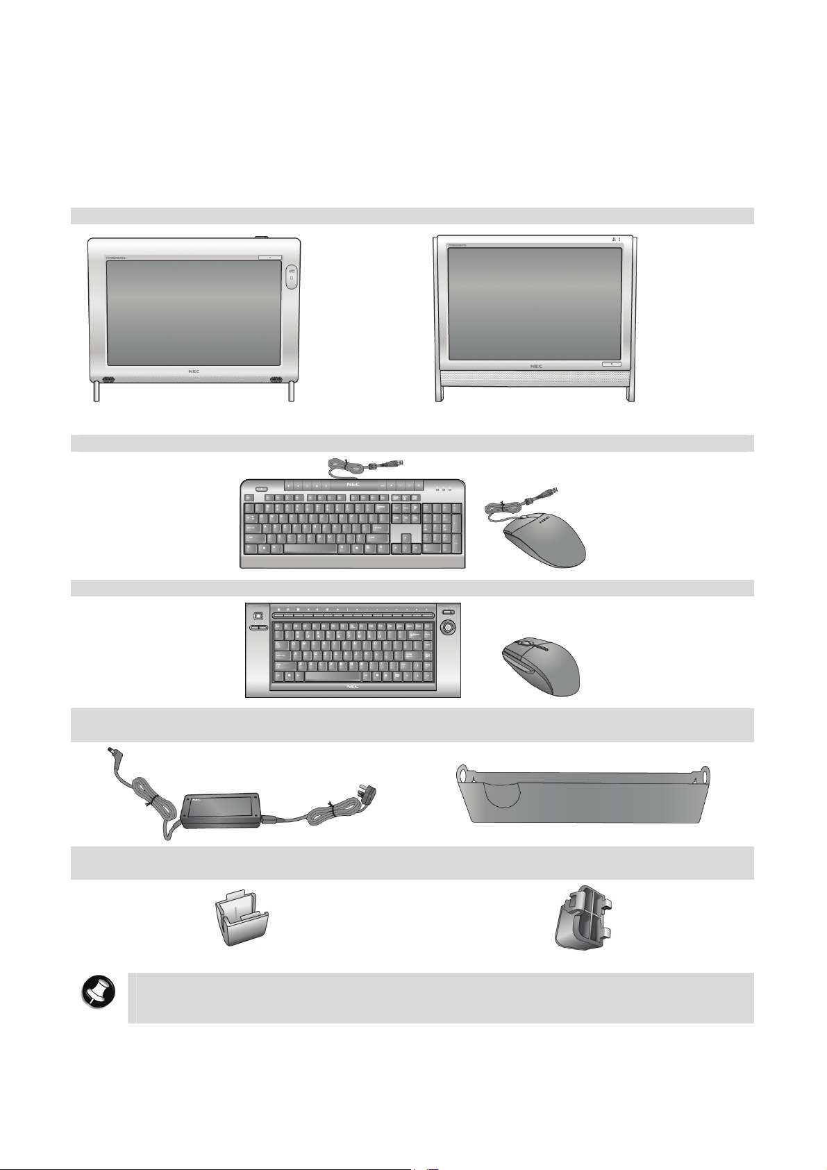
Packing List
Before you begin using your computer, please remove all the items inside the packaging box
and make sure that you have all the items in the packing list, illustrated below.
1. System Unit
P4000 Series P6000 Series
2. Wired Keyboard & Wired Mouse*
3. Wireless Keyboard & Wireless Mouse*
4. Power Cable & AC Adaptor 5. Gadget Pocket (only available for
P4000 series)
6. Cable Cover (only available for
P4000 series)
Note
The illustrations, colours and pictures shown are for descriptive purposes. They
may vary slightly from country to country and the unit you purchase.
- 6 -
7. Hinge Stopper (only available for
P6000 series)
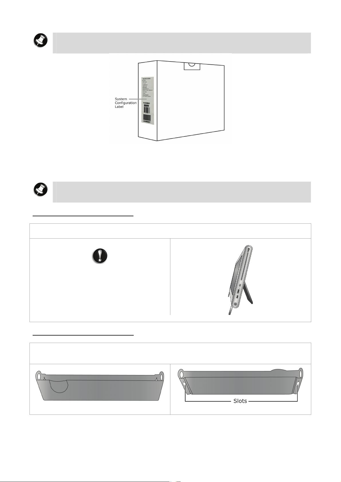
Note
For information on the specification of your computer, please refer to the System
Configuration Label on the packaging box that comes with your system.
Setting Up and Booting Your Computer
The first thing you need to do is to set your computer up correctly, making sure that all the
essential devices and cables are properly connected.
Note
The P4000 series and P6000 series have different setups. For Step 1, please follow
the steps relevant to your system unit before proceeding to Step 2.
Step 1a (for P4000 series only)
The P4000 series system unit is shipped with a complete setup, with its stand already open
and a pre-installed hinge stopper. Place the system unit in its proper position.
CAUTION
Do not force the stand to close or it may
break due to its hinge stopper. If you want to
remove it, refer to the section on “Removing
the Hinge Stopper and Back Cover”.
P4000 series
Step 1b (for P4000 series only)
Installing the Gadget Pocket (only available for P4000 series)
a. The gadget pocket has two slots on its back to allow for attachment on the back of the
system unit.
Front view Back View
- 7 -
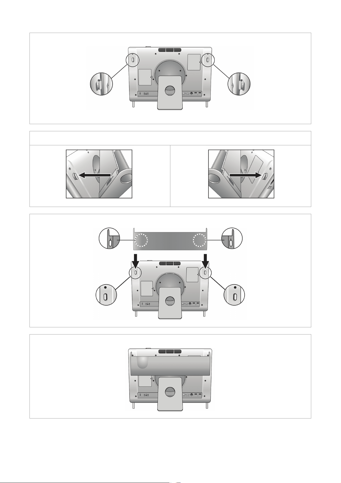
b. The system unit has two fastening clips on its back, one on each side.
Close-up side view of fastening clips
c. Align the slots on the back of the gadget pocket with the fastening clips on the back of the
system unit.
Left slot to left fastening clip Right slot to right fastening clip
d. Push down lightly until the slots are securely fastened onto the fastening clips.
e. The gadget pocket is now ready to use.
- 8 -
f. It can be used to store devices, peripherals and gadgets neatly.
Storing a mouse
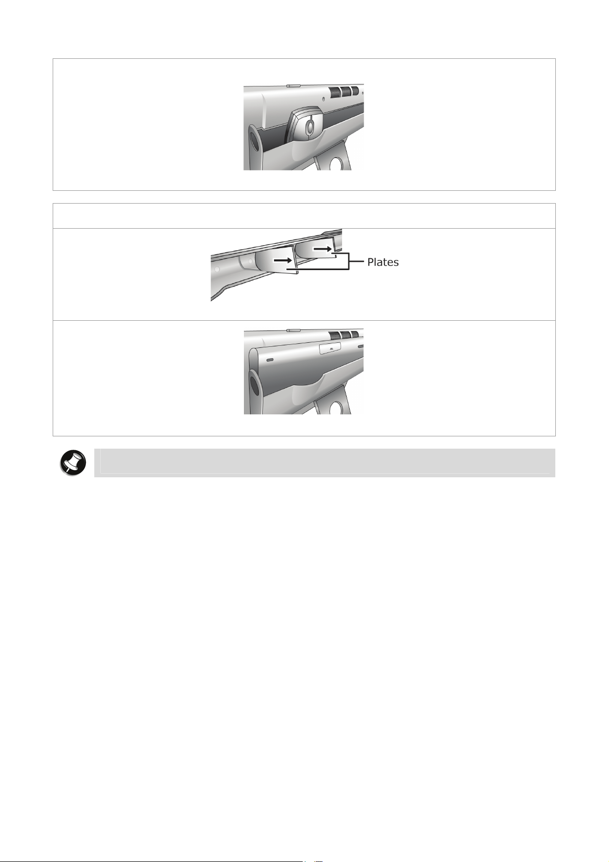
g. To store a keyboard, remove the two plates from inside the gadget pocket first. These
plates can slide in and out along grooves inside the gadget pocket.
Removing the metal plates
Storing a keyboard
Note
Keep the plates in a safe place so that you can use them again when you need them.
- 9 -
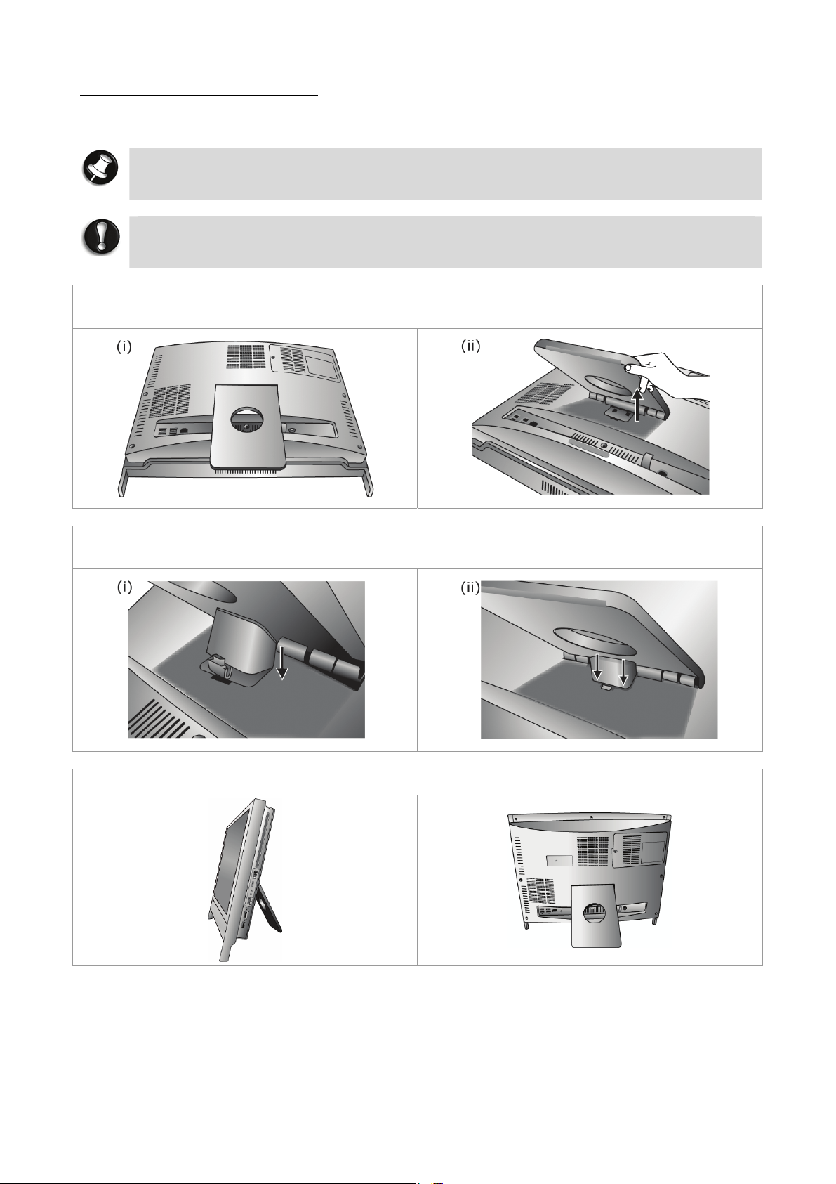
Step 1 (for P6000 series only)
a. Position the system unit carefully so that the screen is facing down.
Note
Use a smooth, flat surface, and cover it with a non-abrasive material such as a soft
cloth to prevent damage to your screen.
CAUTION
The hinge stopper must be installed. Without it, the system unit will fall and may get
damaged.
b. Carefully open the stand. The stand is attached with a spring, so use your hand to hold it
open.
c. Attach the hinge stopper by first inserting the top clips into their corresponding slots.
Secondly, insert the bottom clip into its corresponding slot.
d. Slowly release the stand. Place the system unit in its proper position.
- 10 -
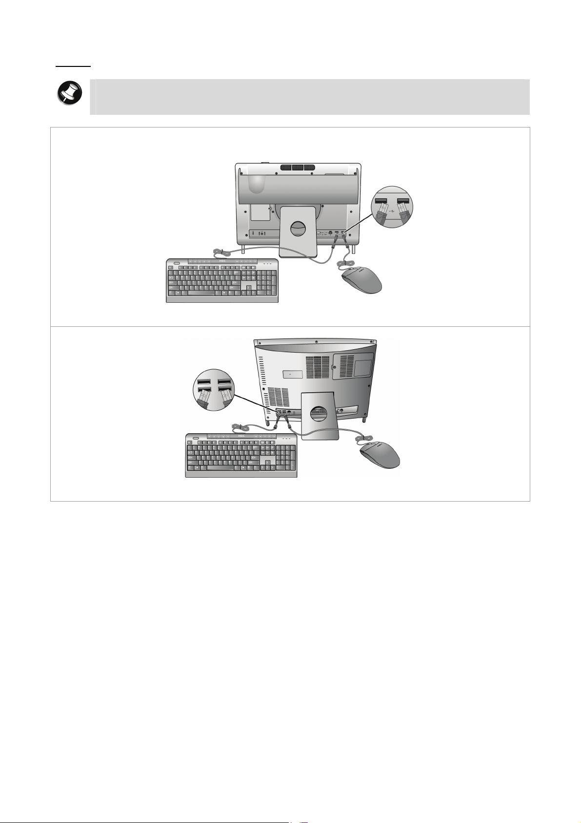
Step 2
Note
If you are using a wireless keyboard and wireless mouse, ignore Step 2 and proceed
to Step 3.
Connect the USB connectors of the keyboard and mouse into any USB ports on the system
unit. In this example we will be using the USB ports located on the back of the system unit.
P4000 series
P6000 series
- 11 -
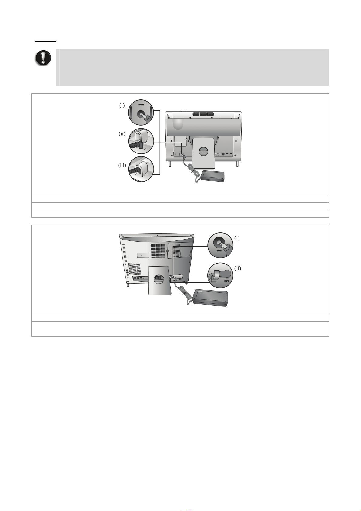
Step 3
CAUTION
Before you connect or disconnect the power cord at the AC Port of your computer,
please ensure that the power plug is disconnected from the wall outlet.
Only use the power cable that comes with your computer. Although other power
cables may look similar, using them may damage your computer.
P4000 series
(i) Now, connect the power cable to the system unit.
(ii) Hold the cable cover over the cable head.
(iii) Push the cover down lightly until it is securely fastened over the cable head.
P6000 series
(i) Now, connect the power cable to the system unit.
(ii) There is a fastening hook located on the P6000 series back panel. This is for slotting in the
power cable so that it does not get tangled.
- 12 -
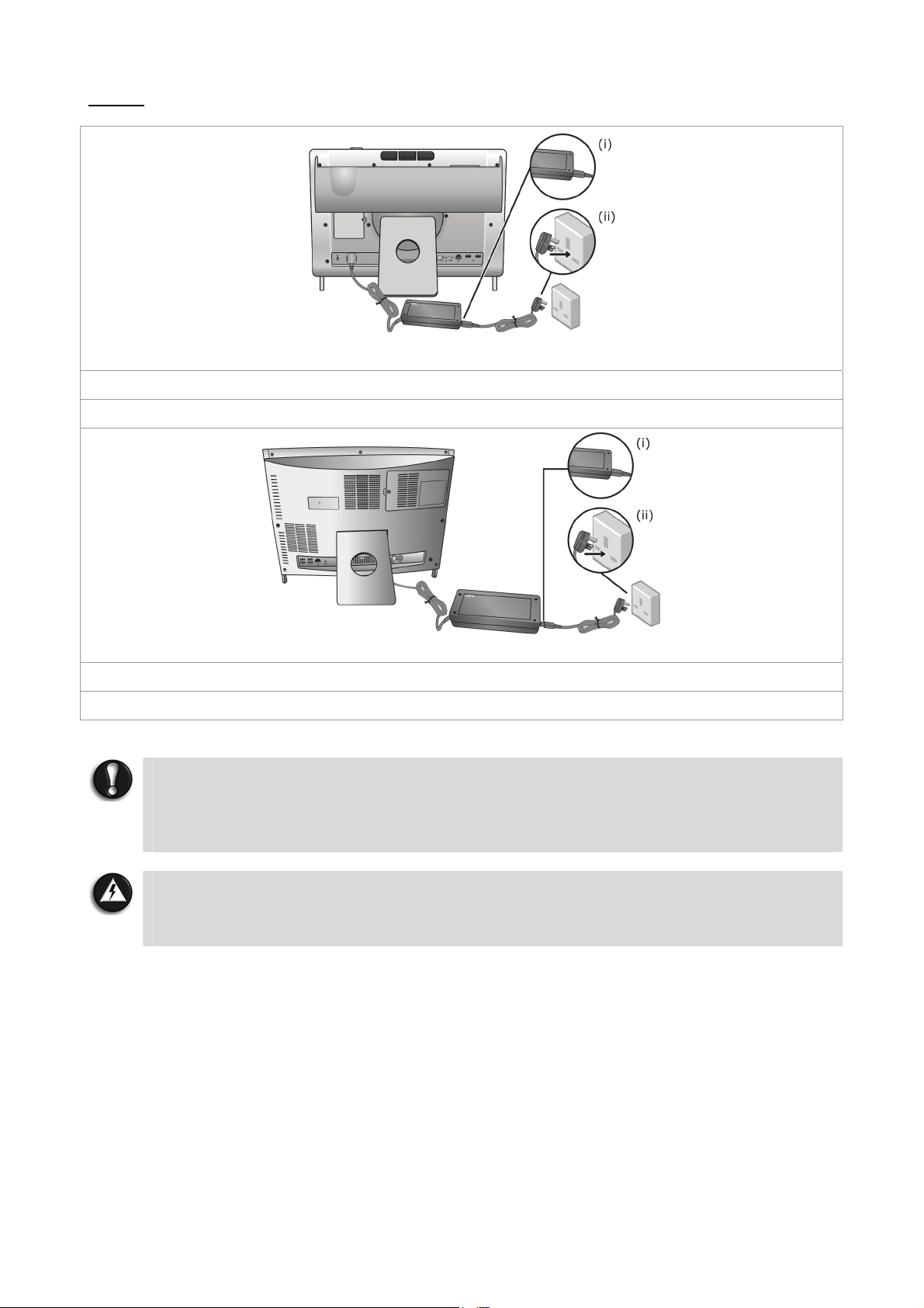
Step 4
P4000 series
(i) Connect the adaptor to the power cable and plug.
(ii) Now, connect its plug to an AC power outlet.
P6000 series
(i) Connect the adaptor to the power cable and plug.
(ii) Now, connect its plug to an AC power outlet.
CAUTION
Do not cover or place objects on the AC adaptor. Keeping the adaptor clear of
objects will allow the adaptor to cool properly during use. Only use the AC adaptor
that comes with your computer. Although other adaptors look similar, using them
can damage your computer.
WARNING
Do not attempt to disassemble the AC adaptor. The AC adaptor has no userreplaceable or serviceable parts inside. Dangerous voltage in the AC adaptor can
cause serious personal injury or death.
- 13 -
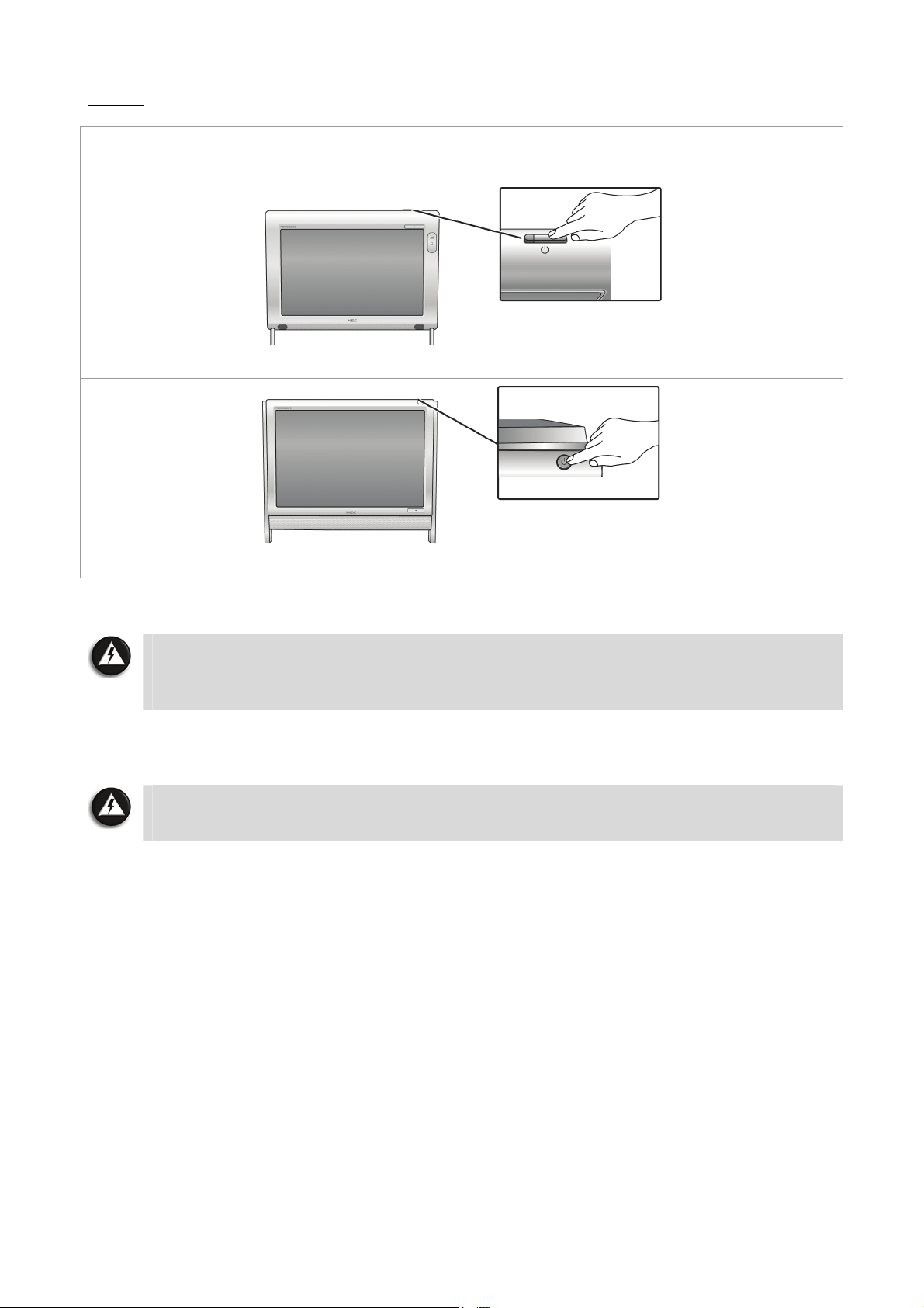
Step 5
Switch on the AC power outlet. Then, press the “Power” button on the system unit to boot or
start up your computer for the first time. The power button is located on the top of the
system.
P4000 series
P6000 series
And that’s all! You’ve successfully booted your computer for the first time.
Note
If you are using a wireless keyboard and wireless mouse, proceed to “Using a Wireless
Keyboard and Wireless Mouse”. Then, proceed to the section on “Setting up Your
Operating System”.
Now, proceed to the section on “Setting up Your Operating System” to learn how to set up
your computer’s operating system.
WARNING
Do not place this computer on your lap and/or allow it to be in contact with any
part of your body while operating.
- 14 -
Using a Wireless Keyboard and Wireless Mouse
Once you have switched on the power to your computer, follow these steps to install your
wireless keyboard and wireless mouse.
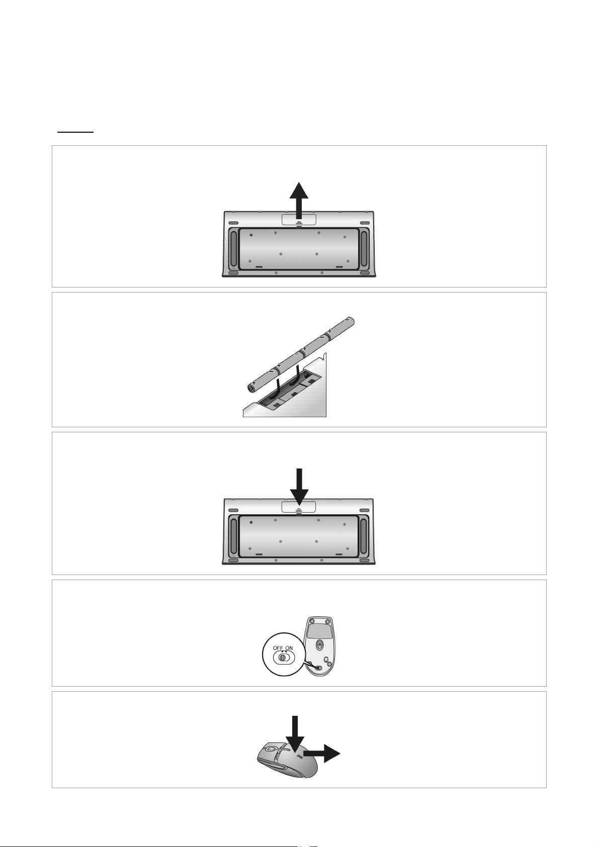
Step 1
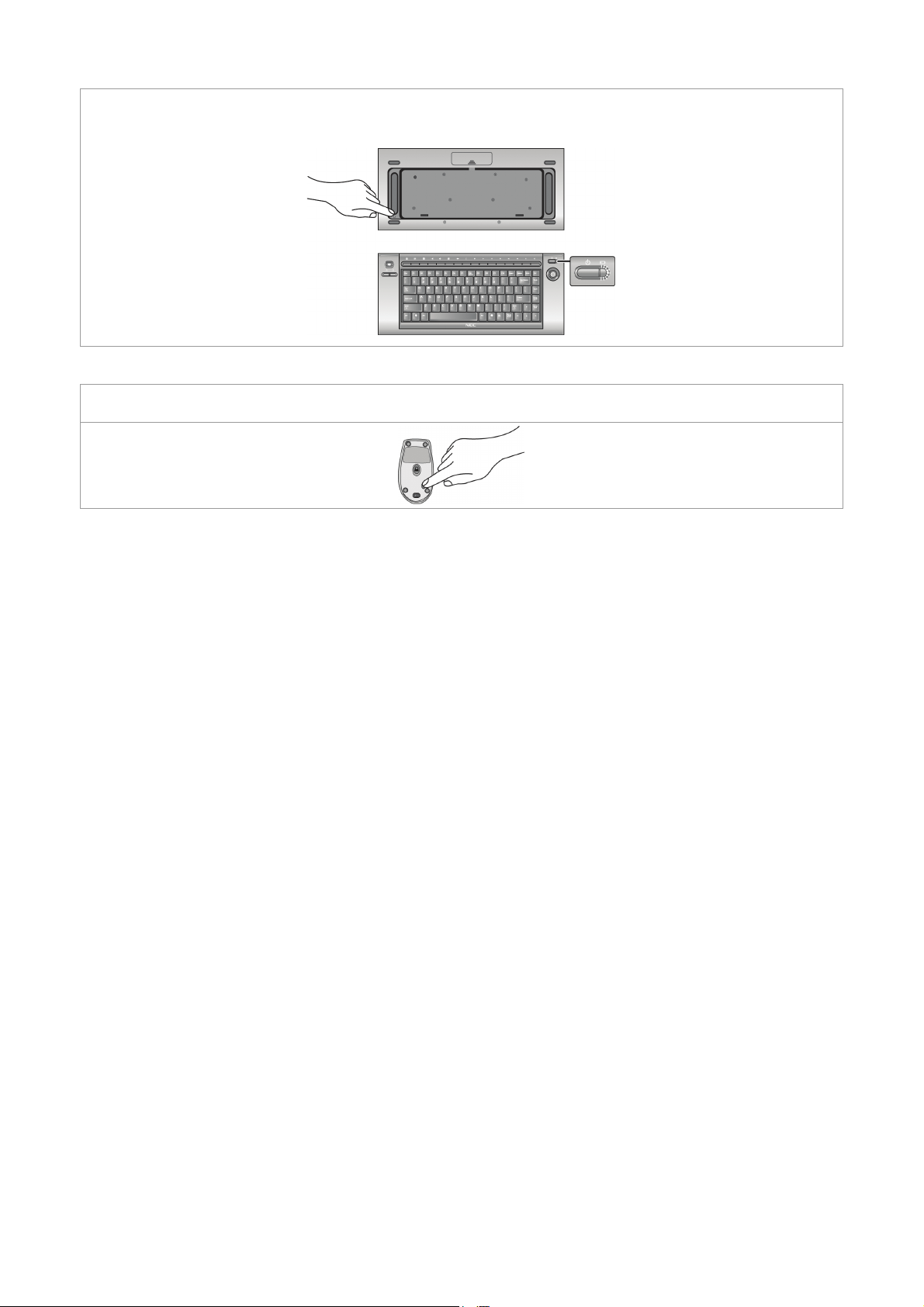
a. Remove the battery compartment cover on the back of the wireless keyboard by
sliding off the cover. Take care not to break the cover.
b. Insert batteries into the battery compartment according to the polarity signs inside the
battery compartment.
c. Place the battery compartment cover on the back of the wireless keyboard by sliding
back the cover.
d. Turn off the power switch of the wireless mouse on the bottom back of the wireless
mouse.
e. Remove the battery compartment cover. Take care not to break the cover.
- 15 -
f. Insert batteries into the battery compartment according to the polarity signs inside the
battery compartment.
g. Place the battery compartment cover on the bottom of the wireless mouse.
h. Turn on the power switch of the wireless mouse on the bottom back of the wireless
mouse.
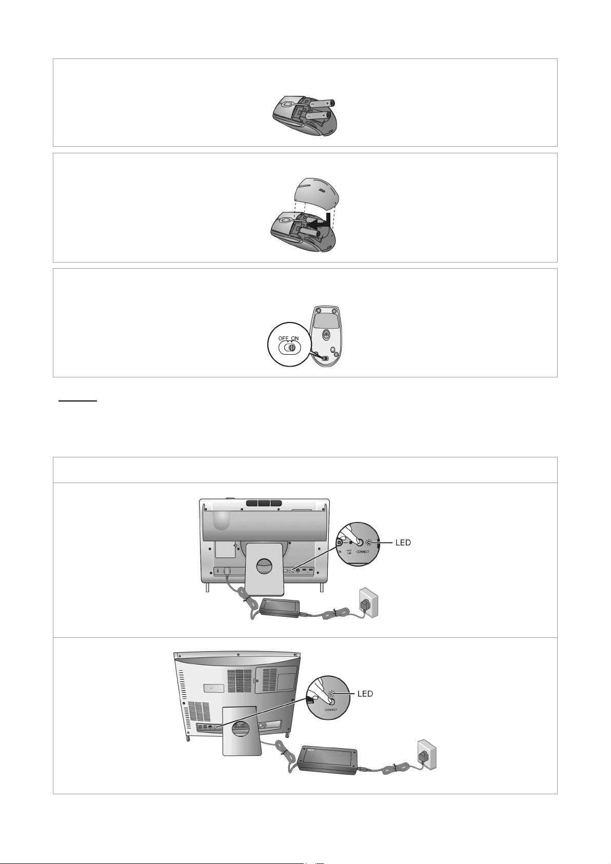
Step 2
Synchronise the keyboard with your system unit
You will now perform the ID-pairing procedure. This is a recognition function that helps to
protect against interference from other RF products in the same environment.
a. Press and hold the connect button on the back of the system unit for about 6 seconds until
its receiver LED flashes.
P4000 series
P6000 series
- 16 -
b. Press and hold the connect button on the bottom of the wireless keyboard for at least
6 seconds until the wireless keyboard LED (on the upper right side of the wireless
keyboard) flashes once. Wait for 1 minute until the connection is established.
Synchronise the mouse with your system unit
c. Press and hold the connect button on the bottom of the wireless mouse for about 6
seconds until its LED is off, then release.
That’s all! You should be able to properly use your wireless keyboard and wireless mouse
now. Changing batteries should not affect the ID-pairing, and you can operate your
wireless keyboard and wireless mouse from up to 10 metres away from the receiver.
Should either the wireless keyboard or wireless mouse fail to work, repeat the steps above
to repair the ID-pairing.
- 17 -
Removing the Hinge Stopper and Back Cover (only available for P4000
series)
The P4000 series system unit may be mounted on a wall using a VESA (Video Electronics
Standards Association) Standard mount. To mount the system unit, you must first remove the
rear stand and back cover.
Note
VESA Standard wall mounting parts can be purchased from a computer accessories
shop. Specific mounting instructions will be provided with the purchased parts. Check
with the supplier you have purchased it from to make sure you obtain the specific
instructions.
a. Position the system unit carefully so that the screen is facing down.
Note
Use a smooth, flat surface, and cover it with a non-abrasive material such as a soft
cloth to prevent damage to your screen.
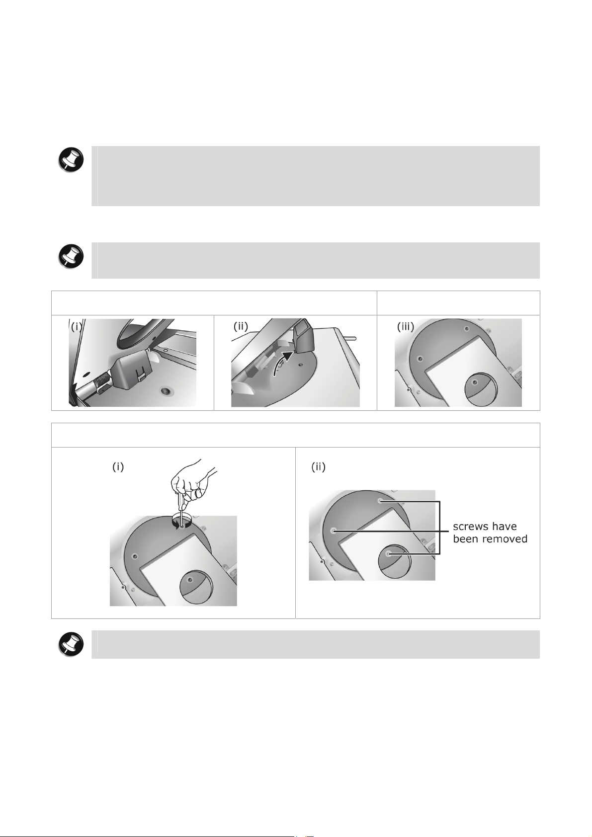
b. Remove the hinge stopper carefully to avoid breaking any
parts.
C. Close the rear stand
d. Remove the screws with a compatible screwdriver.
Note
Keep the screws in a safe place so that you can use them again when you need them.
- 18 -
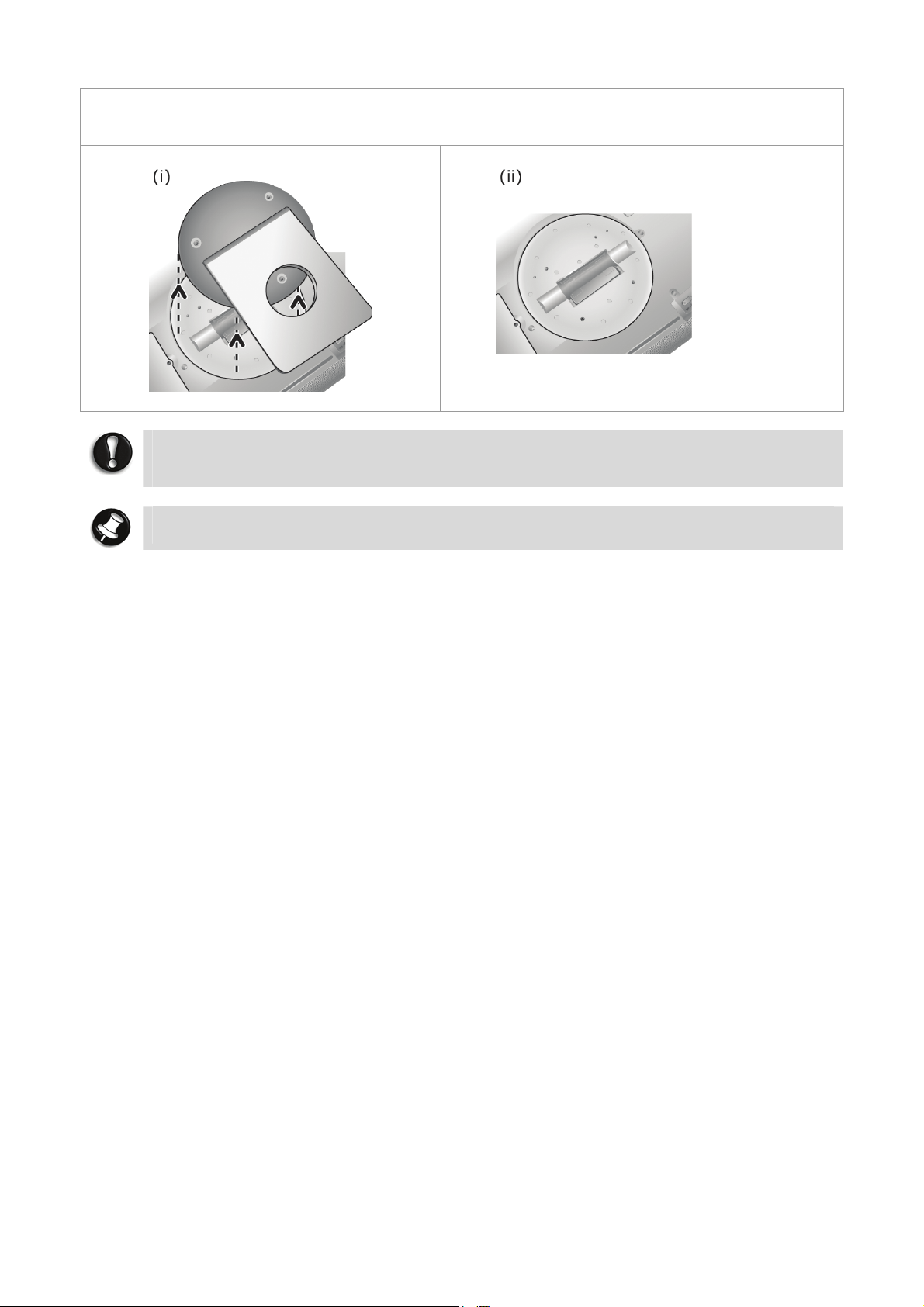
e. Remove the back cover carefully. Your system unit is now ready to install the VESA
Standard wall mounting parts.
back
cover
has
been
removed
CAUTION
When mounting the system unit, please be extra careful not to drop or damage any
parts. Handle all the steps carefully and do not expose yourself to unnecessary risk.
Note
Keep the parts in a safe place so that you can use them again when you need them.
- 19 -

Setting up Your Operating System
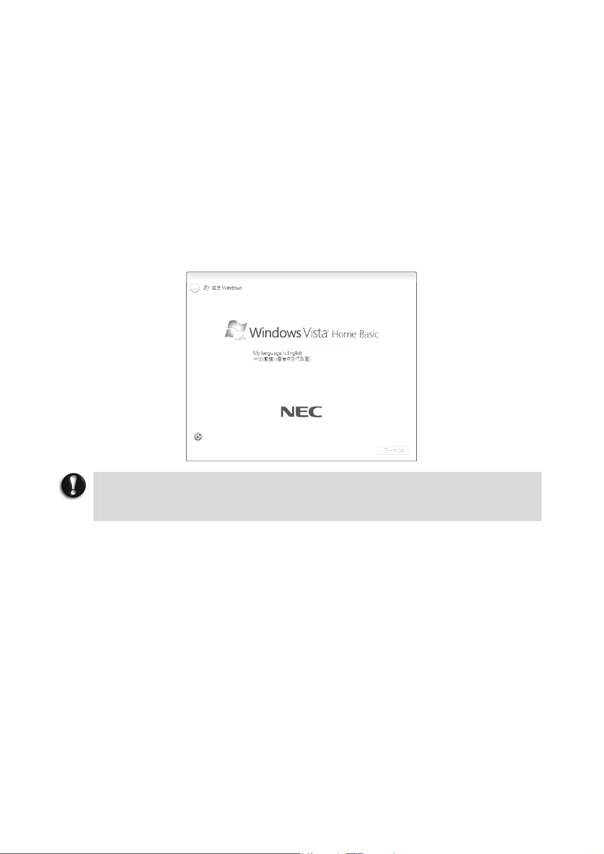
Windows Vista® Operating System Setup
For Windows Vista® Operating system setup
When you switch on the computer, the message “
Please wait a while for the First page of set up Windows
1: Initial Windows
Choose your appropriate Country or Region, Time and Currency, and Keyboard Layout.
Then click the Next button at the lower right corner.
2: The End User License Agreement screen.
Carefully read the license agreement and click in the relevant check box to accept its
terms. Click the Next button.
3: Username and picture selection screen.
Enter a username and password (optional) and also choose a picture at the bottom of
the screen to represent your user account. Click the Next button.
4: Computer name and desktop background selection screen.
Enter a computer name then choose a desktop background from 6 options available at
the bottom of the screen. Click the Next button.
5: Helping protect Windows
There are 3 options available; read each description and click your preferred option.
6: Time and date settings screen.
Choose and set appropriate Time Zone, Date and Time. Click the Next button.
7: Computer’s current location screen.
This page only appears if your computer is connected to a network. There are 3 options
available; read each description and click your preferred option.
8: Thank you! screen.
Click the Start button to complete the Windows Vista
®
setup screen.
®
automatically screen.
©
Microsoft Corporation” will be displayed.
®
screen to be displayed.
®
operating system installation.
- 20 -
Dual Boot (2 languages)
For Hong Kong dual boot models only
Your computer has already been pre-installed with 2 language versions of the Windows Vista
®
operating system, that is, in English and Traditional Chinese. When you start your computer
for the first time, you are required to choose either one of the operating system languages you
prefer (please refer to the screen illustration below). Please select the language you prefer
carefully as this can only be done once.
You will see the message "
moment while the initial Windows
©
Microsoft Corporation” displayed on your screen. Please wait for a
®
setup screen loads. Please refer to section “Windows Vista®
Operating System Setup” for the rest of the instructions.
IMPORTANT
Windows® Language Selection
*This option is applicable to Hong Kong dual boot models only.
CAUTION
Once you have selected the language you prefer, your operating system will be
installed with the selected language permanently. You will not be able to change this
selection for the operating system language.
Referring to the guide provided above, please follow the on screen instructions accordingly.
Windows Vista® FAQ
Please visit our “Questions and Answers” website frequently to obtain the latest information
and updates regarding your system:
http://www.nec-computers-ap.com/faq/vista.asp
- 21 -
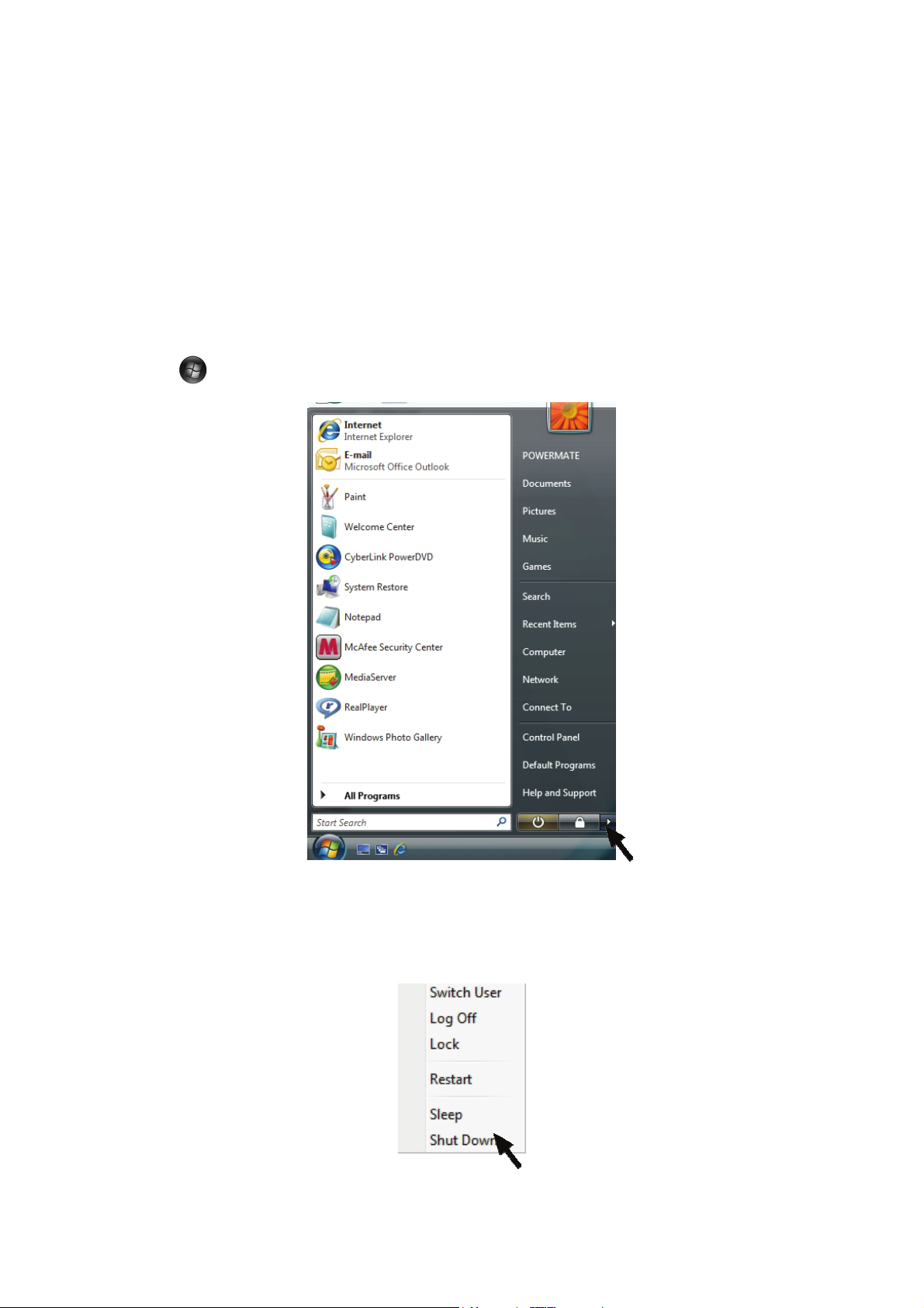
Shutting Down Windows Vista®
When you have finished using the computer, it is important to remember to shut it down
properly. An improper shutting down of the computer can cause important data to be lost or
damaged, and may even cause damage to the computer hardware.
Please follow the steps below to correctly shutdown Windows Vista
computer.
Step 1
Save all of your work before closing them. Then, exit all of the programs that you have
opened. Ensure that there are no programs that have been left open.
Step 2
®
and switch off your
Click Start
on your taskbar. From the menu that appears, click >.
Step 3
Select the “Shut Down” option from the window that appears. Your computer will now shut
down. When your screen goes blank, remember to switch off the main AC power.
- 22 -
Getting To Know Your Computer
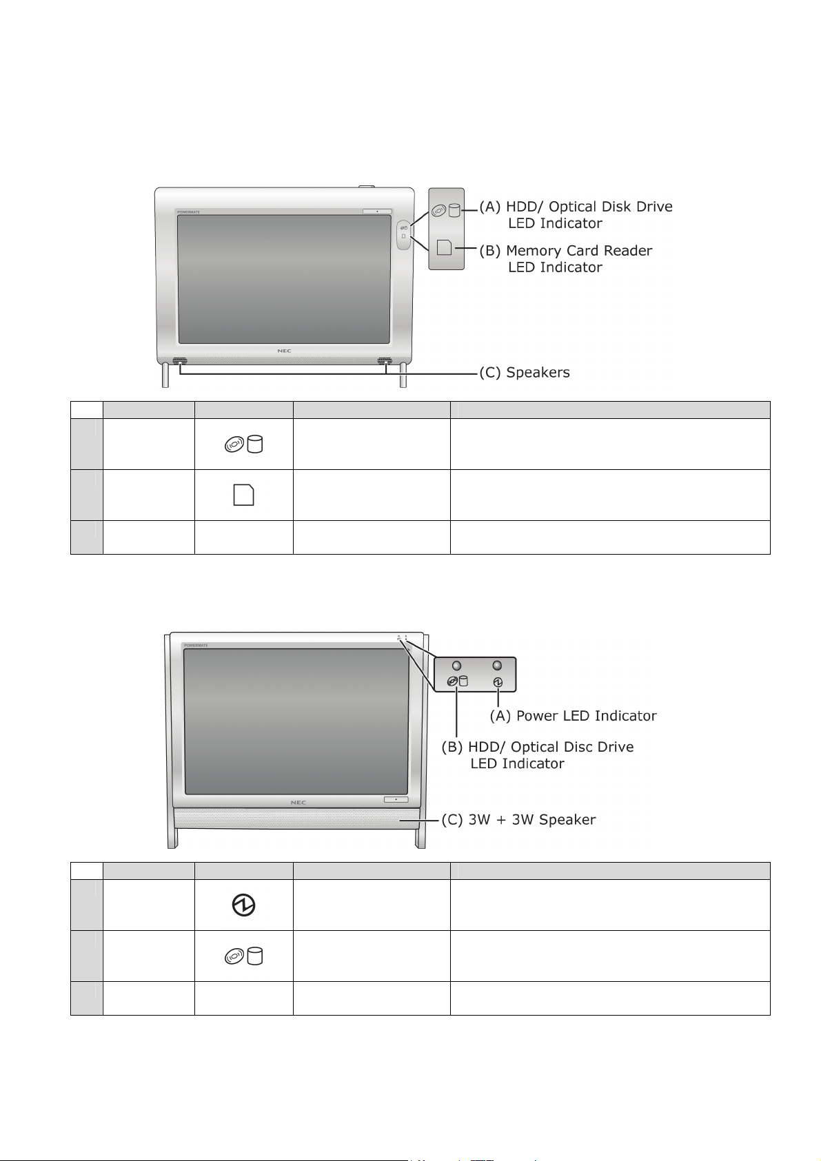
The Front View of the Computer
P4000 series
Part Icon Name Description
A
B
C
N/A
N/A
N/A N/A
HDD/ Optical Disc
Drive LED
Indicator
Memory Card
Reader LED
Indicator
Blinks white. Indicates that the computer is
accessing the hard disk drive or optical disc
drive.
Blinks white. Indicates that the computer is
accessing the memory card reader.
Speakers Provides sound for your multimedia
presentations or listening pleasure.
P6000 series
Part Icon Name Description
A
B
C
N/A
N/A
N/A N/A
Power LED
Indicator
HDD/ Optical Disc
Drive LED
Indicator
When white, indicates that computer is
active. When amber, indicates that
computer is in Standby Mode.
LED blinks white. Indicates that the
computer is accessing the hard disk drive
or optical disc drive.
3W + 3W Speaker Provides sound for your multimedia
presentations or listening pleasure.
- 23 -
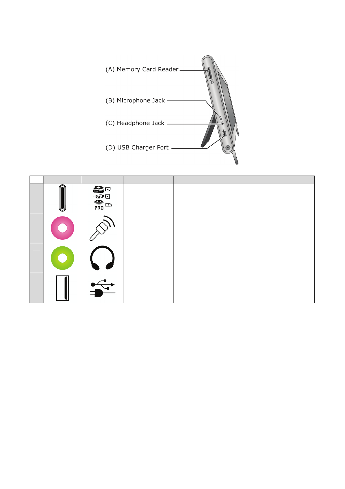
The Left Side View of the Computer
P4000 series
Part Icon Name Description
A
B
C
D
Memory Card
Reader
Microphone
Jack
Headphone
Jack
USB Charger
Port
This slot enables you to read data from SDHC
memory cards.
Allows you to plug in and use a microphone.
Allows you to plug in headphone and listen to
music.
Enables the USB charger mode.
- 24 -
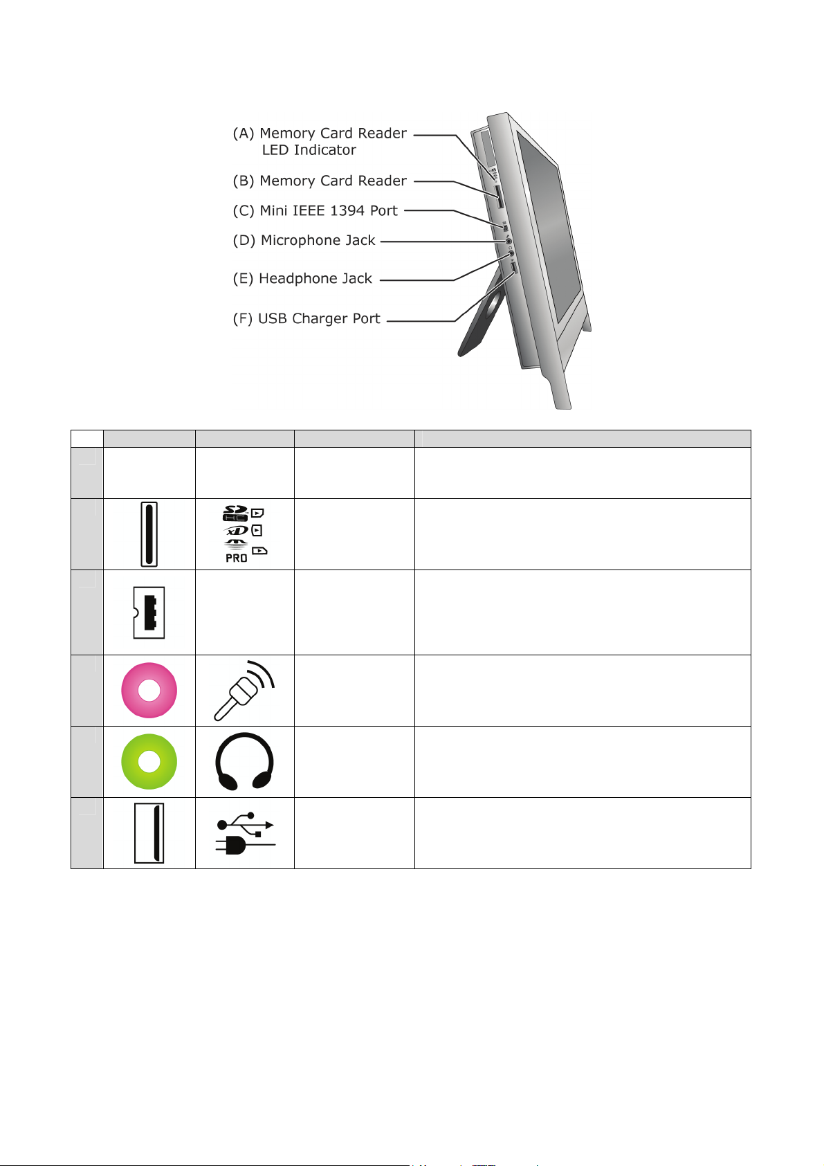
P6000 series
Part Icon Name Description
A
N/A N/A
B
Memory Card
Reader LED
Indicator
Memory Card
Reader
LED blinks blue, when the computer is
accessing the memory card reader.
This slot enables you to read data from SDHC
memory cards.
C
D
E
F
IEEE 1394
Mini IEEE
1394 Port
Microphone
Jack
Headphone
Jack
USB Charger
Port
An IEEE 1394 port (also known as FireWire™
or i.LINK) allows you to connect high-speed
digital devices to your computer, such as
digital video cameras, external hard disk
drives, or scanners.
Allows you to plug in and use a microphone.
Allows you to plug in headphone and listen to
music.
Enables the USB charger mode.
- 25 -
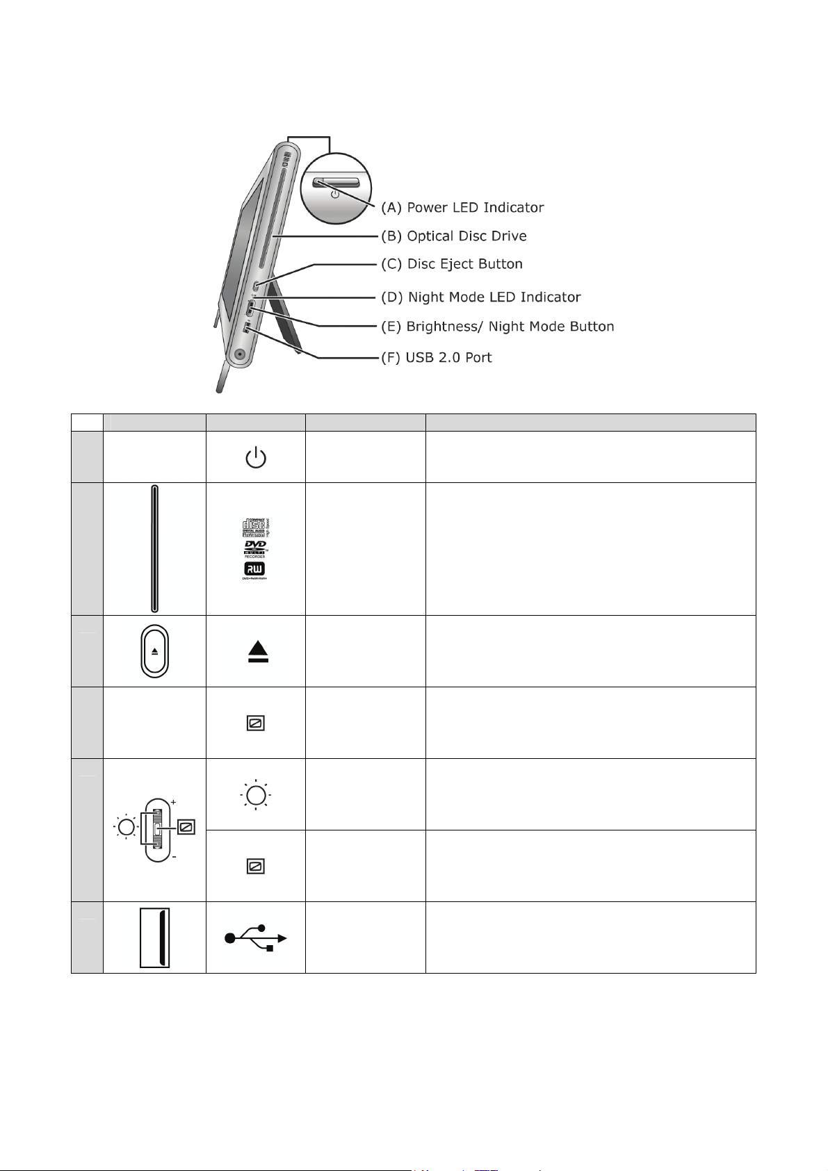
The Right Side View of the Computer
P4000 series
Part Icon Name Description
A
B
C
N/A
Power LED
Indicator
Optical Disc
Drive
Disc Eject
Button
When white, indicates that computer is
active. When amber, indicates that
computer is in Standby Mode.
The optical drive that comes with your
computer depends on the configurations of
the purchased computer. Typically, your
optical drive should be able to access most
common optical discs such as CDs and
DVDs. This drive only supports the standard
5¼ inch (12-cm diameter) optical disc.
Pressing this button opens the optical disc
drive door.
D
E
F
N/A
Night Mode
LED
Indicator
Brightness
Button
Night Mode
Button
USB 2.0 Port The USB allows for instant plug-and-play
When LED is blue, indicates that computer is
in Night Mode (In Night Mode, the screen
switches off while the computer remains
active).
Rolling this button up or down adjusts the
screen brightness.
Pressing this button toggles on/off Night
Mode.
access. It is recommended that you use the
USB ports located on the back panel for USB
devices.
- 26 -
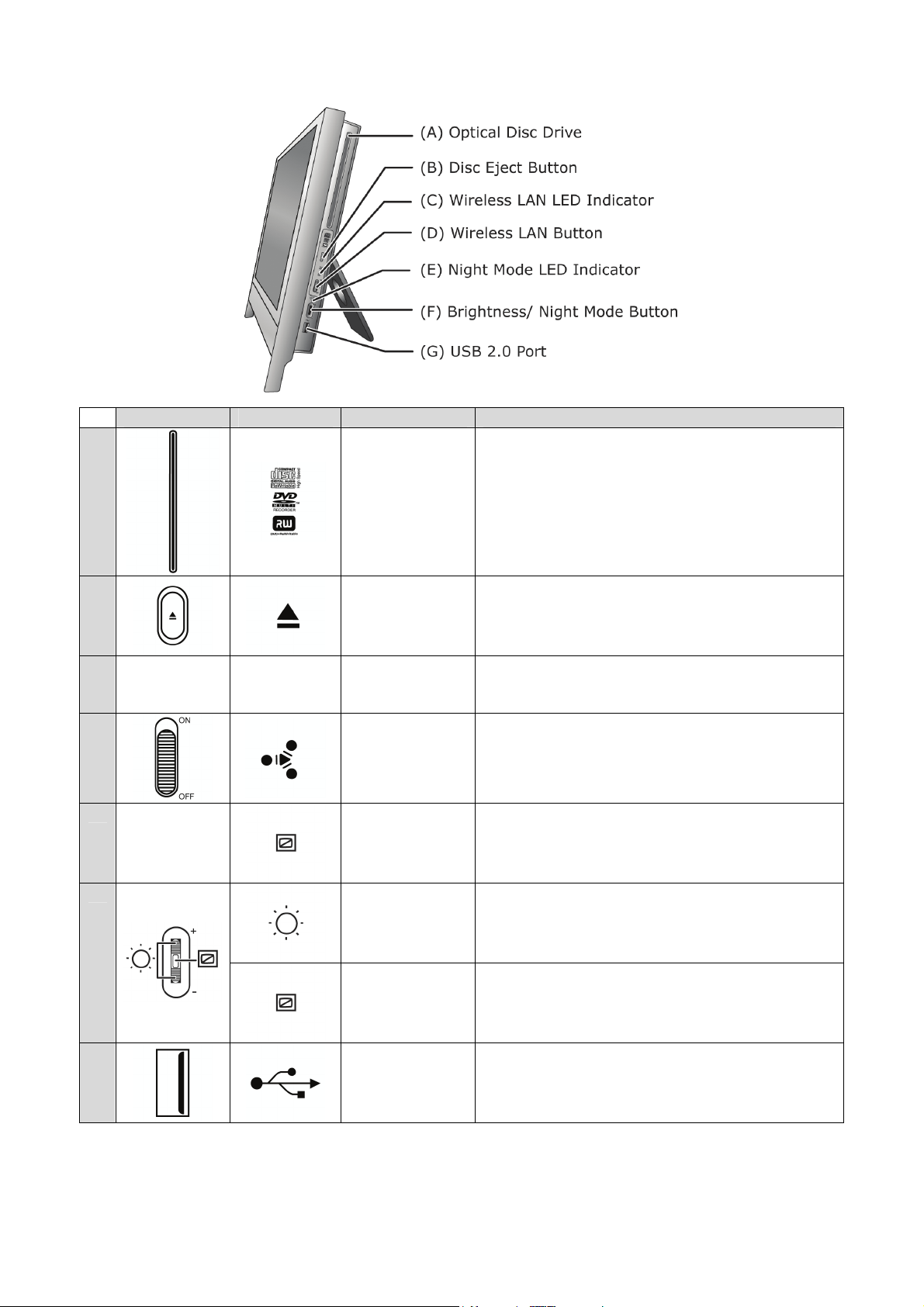
P6000 series
Part Icon Name Description
A
B
C
N/A N/A
D
E
N/A
F
Optical Disc
Drive
Disc Eject
Button
Wireless LAN
LED
Indicator
Wireless LAN
Button
Night Mode
LED
Indicator
Brightness
Button
The optical drive that comes with your
computer depends on the configurations of
the purchased computer. Typically, your
optical drive should be able to access most
common optical discs such as CDs and
DVDs. This drive only supports the standard
5¼ inch (12-cm diameter) optical disc.
Pressing this button opens the optical disc
drive door.
LED blinks blue when Wireless LAN is
enabled.
Enables or disables a Wireless LAN
connection.
When LED is blue, indicates that computer is
in Night Mode. (In Night Mode, the screen
switches off while the computer remains
active).
Rolling this button up or down adjusts the
screen brightness.
G
Night Mode
Button
USB 2.0 Port The USB allows for instant plug-and-play
Pressing this button toggles on/off Night
Mode.
access. It is recommended that you use the
USB ports located on the back panel for USB
devices.
- 27 -
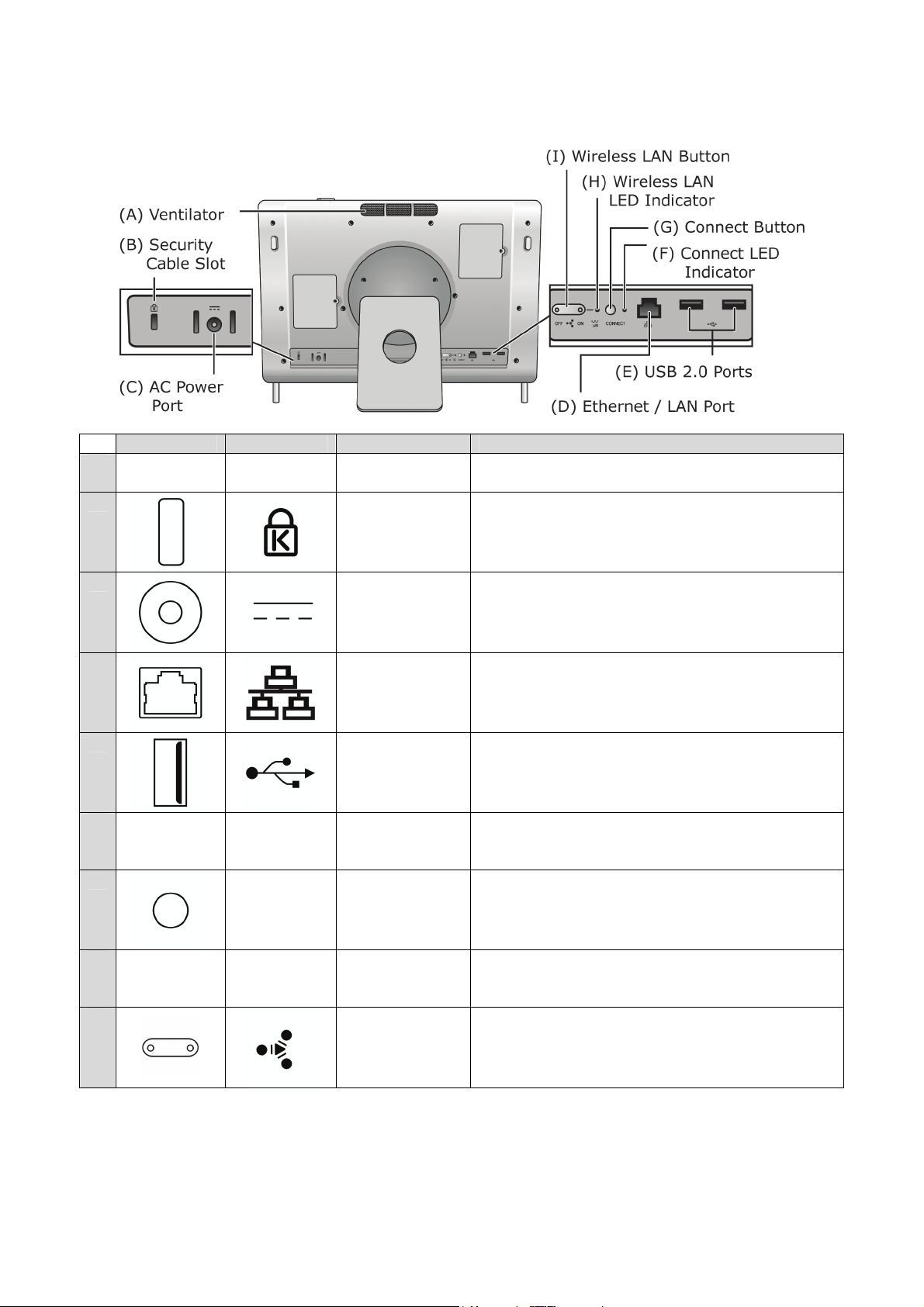
The Back View of the Computer
P4000 series
A
B
Part Icon Name Description
N/A N/A
Ventilator This provides ventilation, to ensure your
Security
Cable Slot
computer’s temperature is optimal.
This slot is for fitting a security cable device
for extra protection of your computer.
C
D
E
F
G
H
I
AC Power
Port
Ethernet /
LAN Port
USB 2.0
Ports
Connect
N/A N/A
Button LED
Indicator
Connect
CONNECT
Button
Wireless LAN
N/A N/A
LED
Indicator
Wireless LAN
button
Lets you connect the computer to an AC
power source.
Connects to a network cable.
The USB allows for instant plug-and-play
access.
LED blinks blue, when the wireless keyboard
or wireless mouse is connected.
Lets you connect a wireless mouse and
wireless keyboard.
LED blinks blue, when Wireless LAN is
enabled.
Enables or disables a Wireless LAN
connection.
- 28 -
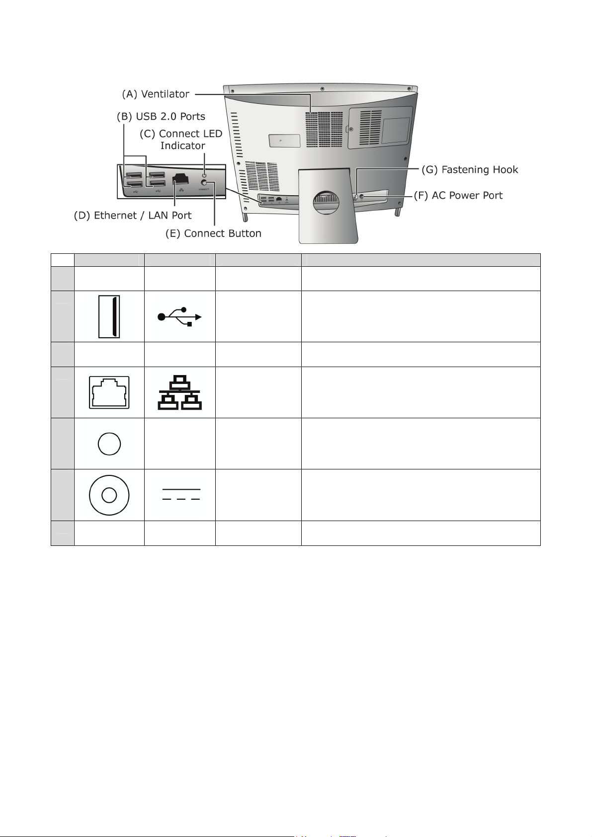
P6000 series
Part Icon Name Description
A
B
C
D
E
F
G
N/A N/A
N/A N/A
CONNECT
N/A N/A
Ventilator This provides ventilation, to ensure your
computer’s temperature is optimal.
USB 2.0
Ports
Connect LED
Indicator
Ethernet /
LAN Port
Connect
Button
AC Power
Port
Fastening
Hook
The USB allows for instant plug-and-play
access.
LED blinks blue, when the wireless keyboard
or wireless mouse is connected.
Connects to a network cable.
Lets you connect a wireless mouse and
wireless keyboard.
Lets you connect the computer to an AC
power source.
This is for slotting in the power cable so that
it does not get tangled.
- 29 -
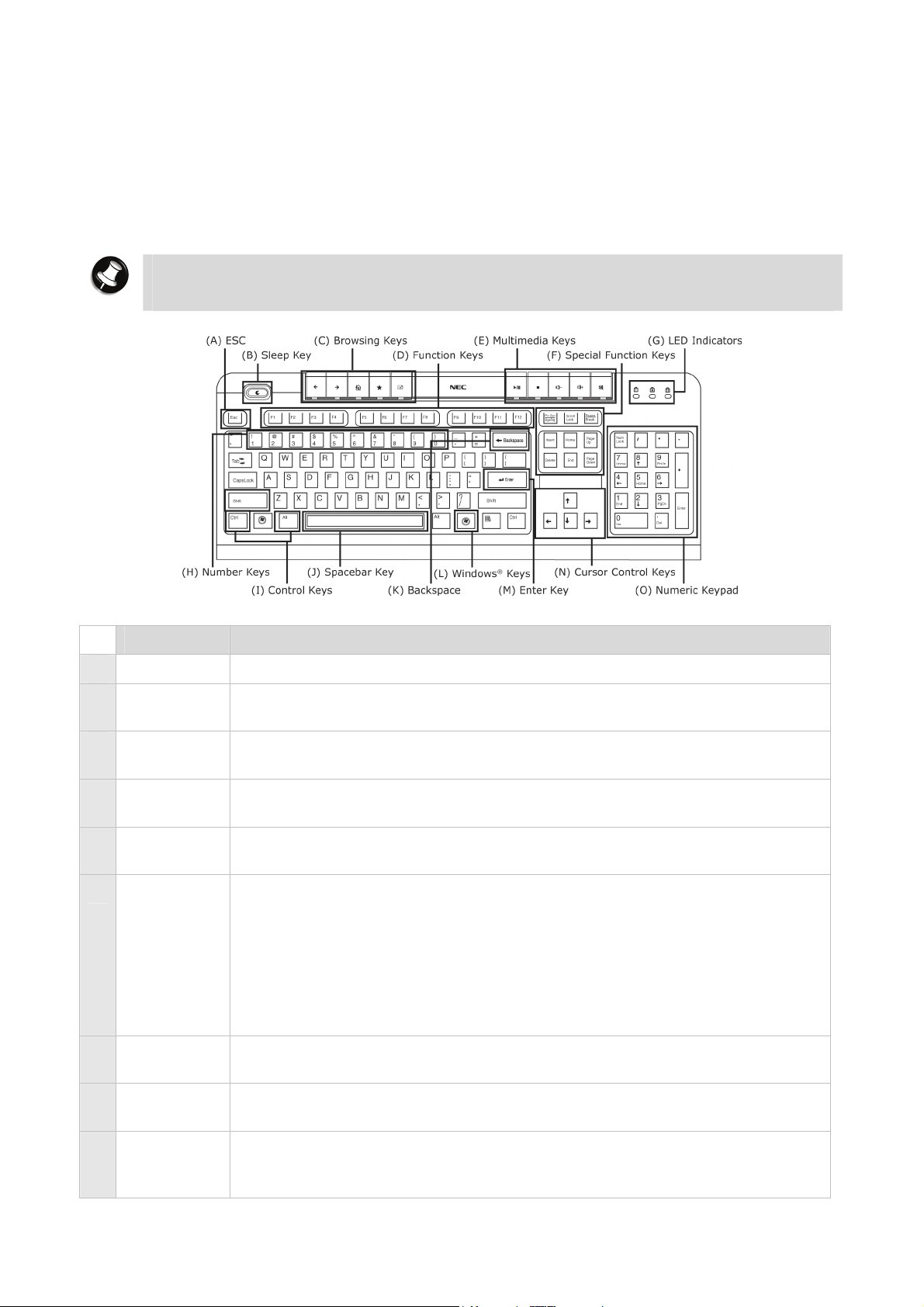
The Keyboard
The wired keyboard
The wired keyboard contains many of the standard keys found on other keyboards. In
addition, the NEC keyboard features special keys called “Hotkeys” which allow the user to
quickly perform functions or launch operations with a single keystroke.
The table below describes each set of keys typically found on the wired keyboard.
Note
The actual keyboard may vary slightly from the one shown here, depending on the
computer model you purchased.
Item Description
A Esc Cancels most current tasks.
B Sleep Key Turn the system into Sleep mode, which it shuts down disk activity and
lowers energy consumption.
C Browsing
Keys
D Function
Browsing keys are available on the keyboard. For more information,
please refer to the section on “Browsing Keys”.
Function keys are available on the keyboard.
Keys
E Multimedia
Keys
F Special
Function
Keys
Multimedia keys available on the keyboard. For more information, please
refer to the section on “Media Keys”.
Lets you position the cursor on the screen where you want to. On the
screen, the cursor is a blinking underline, block or vertical line
depending on the application. The cursor indicates where the next
character or text typed is inserted. Toggling on/off Insert determines
whether characters you type is inserted into or replaces existing ones.
Delete deletes characters or highlighted items. Home brings you to
the start of a line. End takes you to the end of a line. Page Up takes
you one page up. Page Down takes you one page down.
G LED
Indicators
H Number
Keys
I Control
Keys
- 30 -
LED Indicators that light up to indicate certain keyboard settings. For
more information, please refer to the section on “LED Indicators”.
Used to enter numbers or special characters. Press “Shift” simultaneously
for characters on the top.
Ctrl, Alt, Fn and Shift are controls used in conjunction with other keys
to change their functions. To use control keys, press and hold the
control key while pressing any other key.

Item Description
J Spacebar
Used to enter an empty space in your text.
Key
K Backspace Used to go back one space and delete the last key pressed.
®
L Windows
Keys
M Enter Key
(or
Used to facilitate your work. Menu/Application key - provides quick
access to shortcut menus. Windows
®
key–displays the Start Menu.
Used to enter a command, insert a paragraph break in a text or accept a
chosen option.
Return
Key)
N Cursor
Control
Keys
Lets you position the cursor on the screen. On the screen, the cursor
is a blinking underline, block or vertical line depending on the
application. The cursor indicates where the next character/text typed
is inserted.
O Numeric
Keypad
When used with the Num Lock mode on (Pressing Num Lock toggles
the mode on and off), these keys can be used to enter numbers and
mathematical symbols. Otherwise, they can also be used as Cursor
Control keys.
LED Indicators
Item Description
Num Lock
LED
Indicator
Indicates that Num Lock is activated.
Caps Lock
LED
Indicator
Scroll Lock
LED
Indicator
Indicates that Caps Lock is activated.
Indicates that Scroll Lock is activated.
Browsing Keys
Icon Name Description
Back Key Each press of this button brings you back one page in your
browser’s history list of pages visited.
Forward Key Each press of this button brings you forward one page in your
browser’s history list of pages visited.
Home Key Pressing this button will take you to your Homepage (if you
have set one).
Favourite Key Pressing this button will open your Favourites menu (or
Bookmark menu).
Email Key Pressing this button will open your default email application.
- 31 -

Multimedia Keys
Icon Name Description
Play/Pause
Key
Tap the icon once to begin playback of the media player.
Tapping it again resumes playback
Stop Key Tap the icon once to stop the media player.
Volume
Down Key
Volume Up
Key
Tap the icon once to decrease the volume of your system’s
sound/audio.
Tap the icon once to increase the volume of your system’s
sound/audio.
Mute Key Tap the icon once will mute your system’s sound/audio.
- 32 -
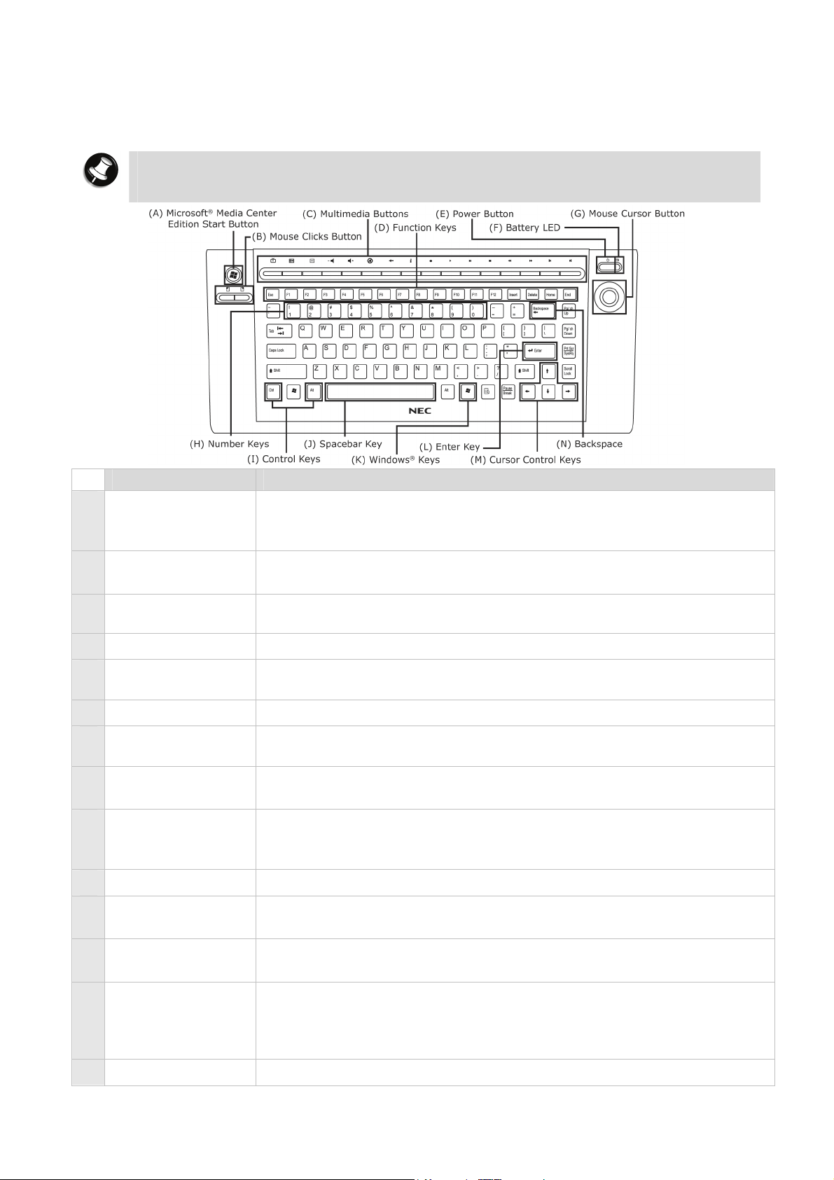
The wireless keyboard
The NEC wireless keyboard provided with some models communicates with the computer via
RF. It features a unique set of Hotkeys specially designed to complement the multimedia
features found in the Media Center Computer.
Note
The actual keyboard may vary slightly from the one shown here, depending on the
computer model you purchased.
Item Description
A Microsoft® Media
Quickly launches the Media Center Computer functions.
Center Edition
Start Button
B Mouse Clicks
Simulates left/right clicking of the mouse.
Button
C Multimedia
Buttons
Multimedia keys available on the keyboard. For more information,
please refer to the section on “Multimedia Buttons”.
D Function Keys Function keys are available on the keyboard.
E Power Button Turn the system into Sleep mode, which it shuts down disk activity
and lowers energy consumption.
F Battery LED Indicates that the wireless keyboard is enabled.
G Mouse Cursor
Enables you to move the mouse cursor by manipulating the button.
Button
H Number Keys Used to enter numbers or special characters. Press “Shift”
simultaneously for characters on the top.
I Control Keys Ctrl, Alt, Fn and Shift are controls used in conjunction with other
keys to change their functions. To use control keys, press and hold
the control key while pressing any other key.
J Spacebar Key Used to enter an empty space in your text.
K Windows® Keys Used to facilitate your work. Menu/Application key - provides quick
access to shortcut menus. Windows
®
key–displays the Start Menu.
L Enter Key Used to enter a command, insert a paragraph break in a text or accept
a chosen option.
M Cursor Control
Keys
Lets you position the cursor on the screen. On the screen, the
cursor is a blinking underline, block or vertical line depending on
the application. The cursor indicates where the next character/text
typed is inserted.
N Backspace Used to go back one space and delete the last key pressed.
- 33 -
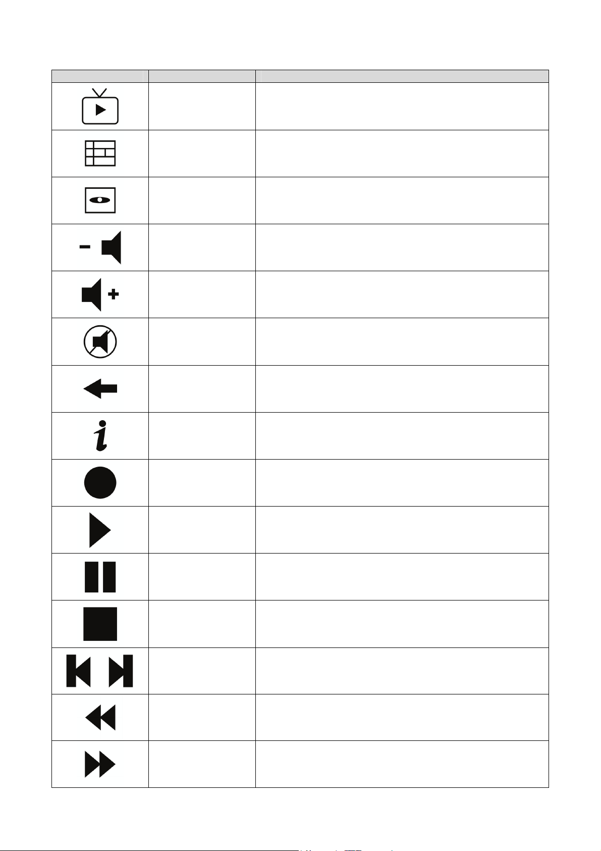
Multimedia Buttons
Symbol Name Function
Live TV Switches to live TV mode on your computer screen or
a television connected to your Media Center Computer.
Guide Takes you to the electronic programming guide.
DVD Menu Displays the DVD Menu.
Volume Down Each press lowers the volume by one unit.
Volume Up Each press increases the volume by one unit.
Mute Cancels audio without stopping playback.
Back Returns to the previous screen.
Information Brings up information about the selected item, if
available.
Record Records active TV programme to disk.
Play Plays the selected media.
Pause Pauses playback of the active media. Pressing it again
resumes playback.
Stop Stops playback for the active media. Pressing Play
starts playback of the media from the beginning.
Rewind/Forward Rewinds/Forwards the playback of the active media.
Replay
(Previous)
Rewinds the playback by one increment; or to the
previous track.
Skip (Next) Skips the playback by one increment; or to the next
track.
- 34 -

The Mouse
The wired/wireless mouse
The wired mouse is a 2-button optical mouse with a scroll wheel/button. The table below
describes the function of each button. The wireless mouse provided with some models
communicates with the computer via RF and functions the same way as a wired mouse.
Wired Mouse Wireless Mouse
Button Function
A Scroll
Wheel/Button
Scrolling the wheel scrolls the screen view up or down. Clicking the
wheel enables a scrolling function, whereby the cursor turns into a
scroll cursor, and you can scroll up/down quickly simply by moving
your mouse up/down.
B Right-click Brings out a pop-up menu.
C Left-click Selects the item that the pointer/cursor is pointing at. Double-click
to start the program the cursor is pointing at, or to select an entire
paragraph when typing text.
D USB Cord and
Connects to a USB port.
Connector
The Optical Drive
If your computer is equipped with a CD or a CD-writer drive, then you will only be able to play
CD-type discs. Some discs vibrate when playing. This does not affect the optical disc drive.
Precautions
To avoid malfunctions or damage to your optical drive, please observe the following tips:
• Insert the disc into the drive before you start a program.
• Do not eject the disc without first closing the program that is using the disc. This could
potentially cause your computer to stop responding.
• Periodically clean the disc to remove any dust or fingerprints. Use a soft, scratch-free cloth
or a commercial disc cleaner. (For a commercial disc cleaner, make sure you check with
the sales representative before you purchase it to confirm its suitability for your disc)
• To keep the disc free of fingerprints, hold the disc with your fingers on the outer edge or
with a finger in the inner circle and a finger on the outer edge.
• Always return the disc to its protective case or sleeve when you have finished using it.
• This optical drive only supports the standard 5 ¼ inch (12-cm diameter) optical disc. Using
non-standard sized media will cause it to get stuck and may damage the drive. Therefore,
inserting a non-standard disc may affect the validity of your optical drive’s warranty.
- 35 -

GENERAL INFORMATION ABOUT OPTICAL DISCS
Disc Care
When handling optical discs, keep the following guidelines in mind:
• Hold optical discs by the outer edge and the inner hub to avoid damaging the surface.
Avoid direct contact with the disc's surface.
• Avoid scratching or soiling both sides of the disc.
• Do not write on or apply labels to either side of the disc. Never write with a ballpoint on the
surface of the disc.
• Do not use stickers, labels or write on both sides of a disc. Unless you use specific label
kits, never use a tape or sticky material to label optical discs. Since the data layer of a disc
is right beneath the printed label, writing with a pen can scratch the thin reflective
aluminium coating. Use soft-tip pens especially for re-writable discs that are even more
sensitive.
• Do not scratch or polish the label side. The pits and lands (microscopic holes and flat
areas) that encode the information in the CD are on the label side, and not on the surface
read by the lens. Large scratches on the underside, however, can often be repaired using
special polishing kits. Most of the time, the laser, which focuses on a layer within the clear
base, is able to see past small scratches, in much the same way the human eye can focus
on objects outside when looking through a window.
• Keep the disc away from direct sunlight, high temperatures, and humidity.
• Keep optical discs away from high temperatures. Don't subject discs at temperature levels
exceeding 37°C. Exposure to direct sunlight over long periods easily warps a disc. Low
temperatures are not a hazard, but wait for a stable temperature before loading a disk.
Discs burned using CD-writer drives are more sensitive and should be stored at room
temperature whenever possible.
• Moisture does not affect other types of discs, but avoid exposing re-writable discs to
liquids. In case of accidental spills on discs, rinse it off with lukewarm water and wipe dry
with a soft cloth. Be careful with sticky or oily substances that trap dirt and dust.
• Proper cleaning is important to achieve optimal performance. Using a soft, slightly damp
cloth, wipe the disc from inside the disc and rub outwards. Do not wipe in circles but clean
in the same outward direction. Wiping the label side in circles can scratch a section of the
data track. Slightly dipping the cloth in warm water is enough. Using cleaners and solvents
can do damage.
• Since discs are coated with thin layers of aluminium and plastic, avoid using benzene, paint
thinner, record cleaner, static repellent, or any other chemical to clean the disc. Chemicals
and cleaners can damage the disc.
Optical Disc Drive Care
To get the most from your optical disc drive, keep the following guidelines in mind:
• Never forcibly pry open a drive whenever a disc gets stuck. If this happens use the eject
button. If that fails, ask for professional help.
• Avoid excessive dirt and dust build-up on optical discs. Optical discs can tolerate
accumulated dirt and dust much better than floppy disks since CDs are not read by direct
contact with the read lens. Excessive dirt, however, will eventually affect the drive's
performance. Thoroughly clean the discs whenever necessary.
The Hard Disk Drive
Commonly referred to as the “hard disk” or “hard drive”, the Hard Disk Drive (HDD) is a
magnetic and non-volatile storage device, and is the primary storage device on your computer.
It stores important files needed to boot your system, as well as program files that allow you to
run software and application.
- 36 -
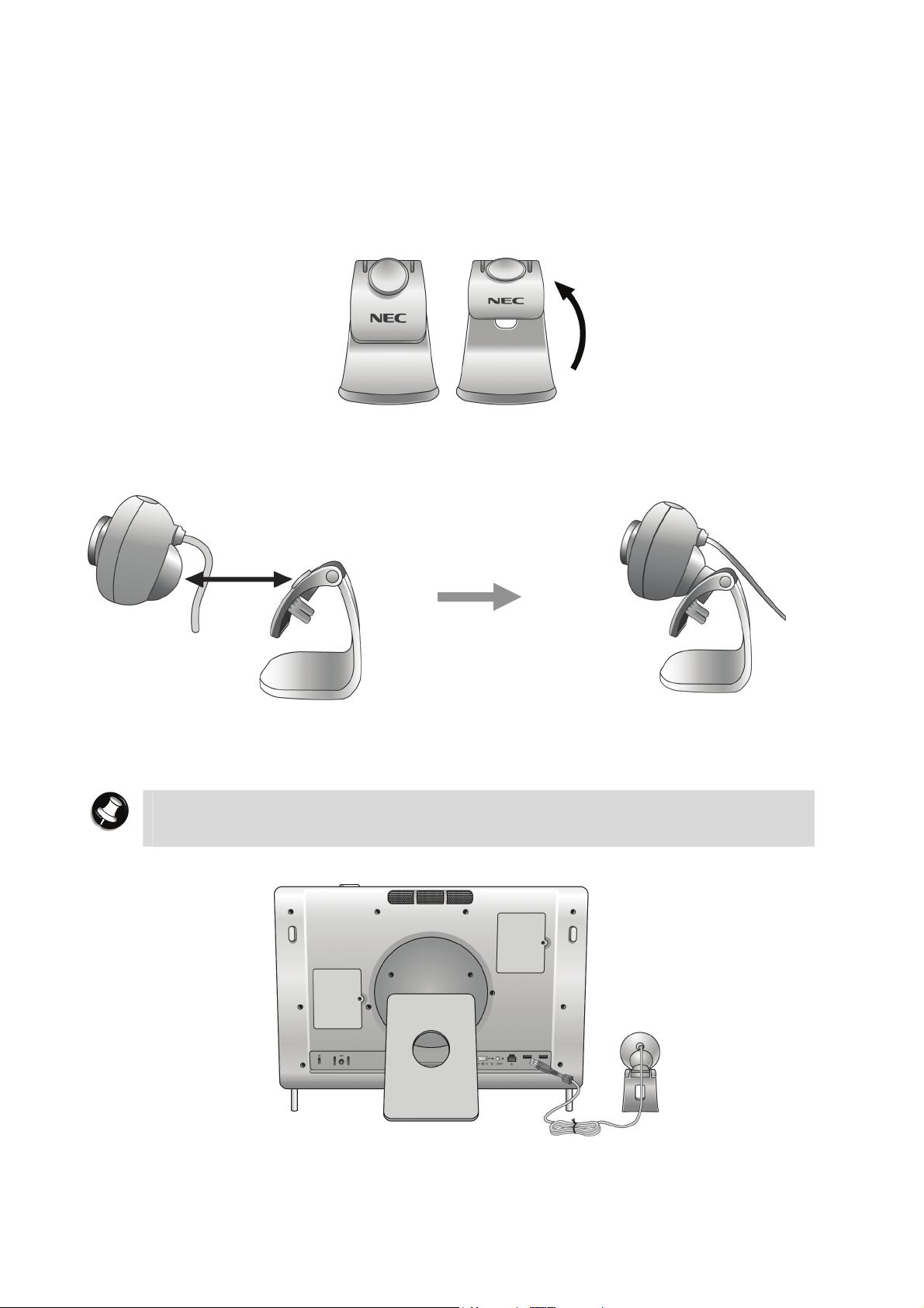
Optional/Peripheral Accessories
Web Camera*
Installing the Web Camera
1. Flip open the web camera stand as shown below.
2. The web camera has a magnetic surface on its back that will be attracted to the magnetic
pad on the stand when placed close to it. Attach the web camera to its stand in this way.
3. Connect the USB connector of the web camera into any USB ports on the system unit. The
web camera should be placed on its own on a flat surface beside the system unit.
Note
It is recommended that you use the USB ports located on the back panel for USB
devices.
- 37 -
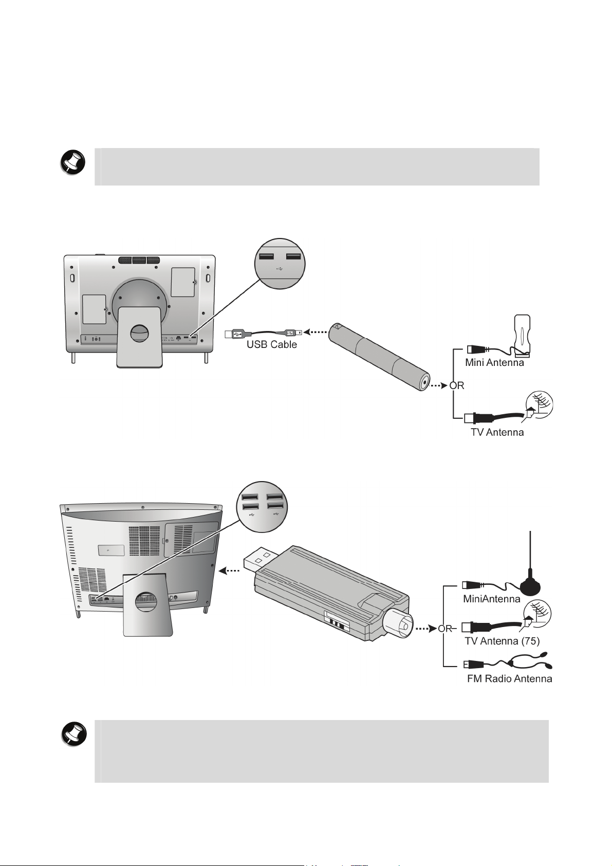
TV Tuner*
Installing the TV Tuner
1. Connect the USB connector on the TV Tuner into a USB port on your computer. It is
recommended that you use a USB port located on the back. Use a USB cable if you need a
longer connection.
Note
It is recommended that you use the USB ports located on the back panel for USB
2. Connect the other end of the TV Tuner to an antenna.
USB DVB/DMB TV Tuner* (applies to Hong Kong region and other countries which share the
same type of broadcast signal)
devices.
USB Analog/DVB TV Tuner* (applies to Australia/New Zealand/Singapore and other
countries which share the same broadcast signal)
3. The TV Tuner will now be automatically installed. You may begin using this device through
the TV application.
Note
The drivers for the TV Tuner will be automatically installed once connected.
However, you need to reboot your computer after installing the TV Tuner to allow
the TV application to detect your tuner device.
The DMB TV Tuner is only supported by the CyberLink TV Enhance application.
- 38 -

Precautions When Using TV Tuner with External Antenna
• The circuit of cable distribution system under consideration is TNV-1 circuit.
• The common sides or earthed side of the circuit are connected to the screen of the coaxial
cable through an antenna connector of tuner and to all accessible parts and circuits (SELV
and accessible metal parts).
• The screen of the coaxial cable is intended to be connected to earth in the building
installation.
- 39 -
COMMUNICATING WITH YOUR COMPUTER
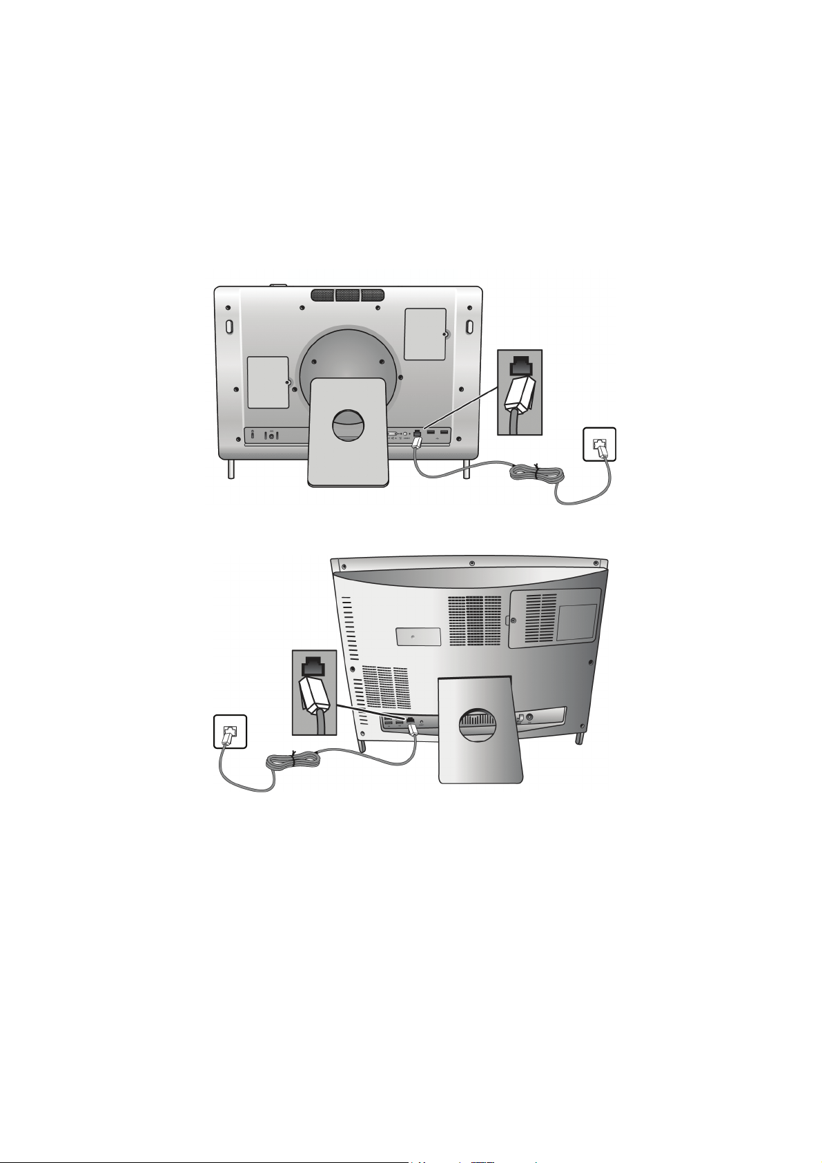
LAN
The internal LAN feature allows you to connect your computer to a local area network. (This is
managed through the Ethernet/LAN port only available on some models.)
Follow these steps to take advantage of the internal LAN feature:
1. Locate the Ethernet/LAN port on the system.
2. Plug one end of your LAN cable into the Ethernet/LAN port jack.
3. Plug the other end of the LAN cable to a local area network.
P4000 series
P6000 series
- 40 -

WIRELESS LAN
The Wireless LAN feature allows you to connect your computer to a local area network using a
wireless connection.
For P4000 series series, slide the Wireless LAN button on the back panel of the system unit to
the “On” position.
The Wireless LAN LED will light up, indicating that the Wireless LAN is enabled.
For P6000 series series, slide the Wireless LAN button on the right side panel of the system
unit to the “On” position.
The Wireless LAN LED will light up, indicating that the Wireless LAN is enabled.
- 41 -

Applications
Adobe® Reader®*
Adobe
your local network, or the Internet.
Access to Adobe
1. Double click the Adobe
2. Adobe
agreement, click “Accept”.
3. Next, beyond Adobe
Adobe
The software varies according to the model and is subject to change without notice (for
specific models only).
®
Reader® allows you to view, navigate, and print PDF files from your local hard drive,
®
Reader®
®
Reader® license agreement screen will appear. After you have already read the
®
Reader® now!”.
®
Reader® icon to launch the application.
®
Reader® screen will appear, then click “Click here to open beyond
- 42 -

CyberLink Live*
Share Media and Access TV Anytime, Anywhere
• Watch your favourite TV shows from anywhere in the world via Internet.
• Access live video feed captured by webcams via CyberLink Live.
• Enjoy photos, music and videos from your home wherever you are.
• Access your media files directly, no need for lengthy uploads.
• Broadcast your media to friends & family, right from your computer.
Share your media over the Internet with CyberLink Live
CyberLink Live gives you a private and secure way to access the multimedia content stored on
your home computer - even if you are away from home. You can also share your multimedia
to other computers directly from your home computer. No need for lengthy media file uploads.
Your friends and family get access using their own web browser.
Your "Anywhere Access" to Personal Documents and Multimedia
• Live TV Programs
With a TV tuner card connected to your home computer, you can tune in and catch up with
your local shows wherever you are.
• Anywhere Entertainment
Now the video, photo, and music files located on your home computer can be accessed
remotely anytime, anywhere. Only a web browser is required.
• Your Global Office
Direct access to the data files stored on your home computer allows you to view and
download your work related documents wherever you are.
• Better Control
CyberLink Live ensures you have better control of your own digital media, because your
files are stored on your home computer.
• Live Videos from Webcams
While you are away, capture live videos of your home, office or pets via webcam, and
watch remotely via CyberLink Live.
- 43 -

Sharing Your Multimedia with Others
• Share Media
Share your best photos, favourite videos and audio collections to friends and family.
CyberLink Live offers a secure way to share your media directly from your computer. No
need for lengthy uploads.
• Express Yourself
CyberLink Live allows you to describe and rank your multimedia, so you can share the
content you've created, and share your stories too.
• Build a community
While your invited guests are enjoying your multimedia content, they can post comments
to you. You can then join a group discussion regarding your media on CyberLink Live.
The software varies according to the model and is subject to change without notice (for
specific models only).
- 44 -

CyberLink MagicDirector *
• Magical Video Editing for the Digital Home.
• Easy-to-use video editing software featuring CyberLink technology that automatically
cleans and edits video content.
• Used in conjunction with digital home software such as award-winning CyberLink PowerCinema,
CyberLink PowerDVD or Windows
editing via remote control.
®
Media Center Edition (MCE), MagicDirector redefines video
Stylised Video Themes Turn Up the Excitement
MagicDirector offers multiple options for creating themed videos with exciting movie styles to
fit any occasion: Party, Wedding and Baby. Transitions and frames are added to your movie
while movie titles can be typed via real or on-screen virtual keyboard. For the final touch,
background music can be mixed to a video's audio track.
Video Scenes Editing Made Simple
Three simple video scene editing selections are available when using MagicDirector to
include , exclude or automatically decide to keep or cut out scenes. With a simple
"thumbs up", "thumbs down", and "OK" concept, you can also edit swiftly and easily via
remote control.
One-click Video and Audio Cleaning
MagicDirector includes CyberLink’s advanced Eagle Vision (CLEV) and Noise Reduction (CLNR)
technologies, letting you improve the image and audio quality of your videos. CLEV enhances
colours and balances contrast and brightness. CLNR eliminates unwanted and often distracting
noises that appear in home videos — such as wind, water, and machinery — without removing
audio such as crucial dialogue.
Flexible Options for Setting Video Quality
With five quality settings, MagicDirector lets you choose the highest video quality suited to the
disc type according to available space left on your disc. Both NTSC and PAL TV formats are
supported. You will also have the choice between LPCM and Dolby audio for audio settings.
Complete Remote Control Operation
MagicDirector supports remote-control navigation—features are activated via simple arrow and
OK controls. (CyberLink’s Remote Control is available online as an optional extra for
PowerCinema.)
- 45 -

Key features of "CyberLink MagicDirector":
• Edit videos from PowerCinema using a remote control.
• Personalise your videos with magical movie styles.
• Keep your best clips, remove the worst, and let MagicDirector decide the rest.
• Use Magic Clean to enhance your video's images and audio.
• Choose your video quality to meet your file size requirements.
• Burn to DVD with optional Make DVD.
The software varies according to the model and is subject to change without notice (for
specific models only).
- 46 -

CyberLink MagicSports 3.0*
• Watch and control TV sports programmes with multiple features.
• Lets you experience TV sports programmes like never before by creating your own soccer
highlights.
• Gives greater control over watching recorded TV sports programmes by allowing quick
replay of special moments such as near-goals and goals, fouls, corners and penalties.
• Quickly identify exciting game moments. Navigate to the next exciting moment. Watch the
rest of the game from any highlight.
Key features of "CyberLink MagicSports":
• Fast analysis and navigation of recorded TV sports programmes.
• Auto identification of exciting sports highlights.
• Instant replays of your favourite game moments.
• Star ratings for the most exciting baseball highlights.
• Compatibility with PowerCinema and Windows
The software varies according to the model and is subject to change without notice (for
specific models only).
®
Media Center Edition.
- 47 -
CyberLink MakeDisc 3*
Easy DVD Burning for the Digital Home
• Burn videos and photo slideshows to CDs, DVDs as well as Blu-Ray discs.
• Import recorded TV Shows and burn to CDs, DVDs as well as Blu-Ray discs.
• Select a themed menu for easy DVD navigation.
• Backup data files onto CDs and DVDs.
• Create music CDs from MP3 or WMA files.
Create DVDs from your Favourite Videos and Photos
MakeDisc enhances Windows® Media Center with these features:
• Authoring and burning videos to CDs, DVDs as well as Blu-Ray discs.
• Authoring and burning photo slideshows to CDs, DVDs as well as Blu-Ray discs.
• Adding a disc menu from a range of built-in templates.
• Burning music to Audio CD, or as an MP3/WMA disc.
• Burning data to CDs and DVDs.
Import All Kinds of File Formats – Including Record TV
• Auto detection of TV aspect ratios ensures that recorded TV programs are output and
authored in the same menu size as the captured content. MakeDisc intelligently detects the
aspect ratio of the majority of the captured digital TV content, not just the first frame like
other software.
• MakeDisc is compatible with the most popular data, video, photo and music formats which
makes for easy creation of data CDs and DVDs, music CDs, video DVDs, mixed
photo/video CDs and DVDs.
Create Stylish DVD Menus
• Choose from thematic menu styles for your photo slideshow and video DVDs.
• Add background music by choosing MP3, WAV and WMA formats from your hard drive.
Burn to CDs, DVDs and Blu-Ray Discs
• MakeDisc supports a broad range of disc types and burners, including CD-R/+R, CD-
RW/+RW, DVD-R/+R, DVD-RW/+RW, double layer discs/drives and Blu-Ray discs.
• Automatically fit your video/slideshow onto your available DVD space with Smart Fit.
The software varies according to the model and is subject to change without notice (for
specific models only).
- 48 -
CyberLink Media Server*
The CyberLink Media Server application allows sharing your media files with your family
members within your home network. Media Server shares all of your media files across the
network with any computer that has CyberLink SoftDMA installed.
Access to CyberLink Media Server
1. Double click the CyberLink Media Server icon to launch the application.
2. CyberLink Media Server main display screen will appear.
As part of its effort to provide you with the complete digital home experience, NEC is proud to
present you with 1 licensed copy of SoftDMA that can be installed onto any of your other
existing computers.
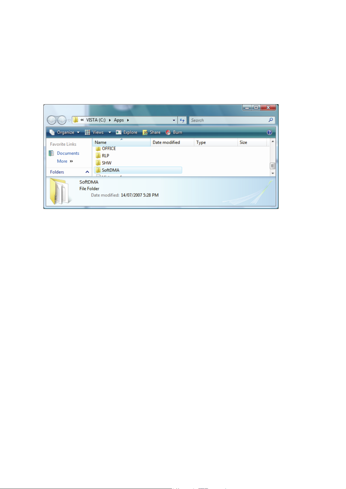
The SoftDMA installation files are located in the folder: c:\Apps\SoftDMA.
You need to transfer all the files in the SoftDMA folder to a removable media such as USB flash
drives and CDR. On the targeted computer, run SETUP.EXE to install SoftDMA.
The setup process will require an installation key and it can be obtained upon completion of
warranty registration. Kindly register your NEC Computer at: “http://www.nec-computersap.com/regwarranty” or contact your local call centre for further assistance.
The software varies according to the model and is subject to change without notice (for
specific models only).
- 49 -

CyberLink PowerCinema 5*
The TV Entertainment Centre for the Digital Home.
• Watch analog and digital TV programmes with time-shift playback.
• Record your favourite TV and radio shows with smart scheduling.
• Search for TV programmes that match your interests via EPG.
• Watch two channels simultaneously using PiP mode.
• Play DVDs, videos, photos, and music. Get online news and weather info.
Your Complete Centre for Digital Home Entertainment
TV on the computer: schedule, record, and watch your favourite shows
• Search for programmes by name, category, and channel.
• Schedule your computer to record shows while you are out.
• Catch up on the action of live TV shows even after they've started, with time-shift
recording.
• Record programmes to a hard disk.
• Switch between channels, language settings and subtitles.
DVDs, Videos, Music, and Pictures: watch, listen, and enjoy
• Play movie DVDs with Dolby Digital audio.
• Watch widescreen movies in their true display ratio.
• Sync music files with your portable media player.
• Remove photo red-eyes, auto fix contrast and brightness.
• Display photos as a slideshow with background music and transition effects.
News and Weather, More Options
• Access live weather and news information.
• Change your interface colours and themes.
• Expand functionality with packs for video editing, disc burning and watching sports
highlights.
• Enrich the movie experience with the Advanced Audio Pack of home-theatre technologies.
The software varies according to the model and is subject to change without notice (for
specific models only).
- 50 -

CyberLink PowerDVD 7.3*
PowerDVD is the latest evolution of the world-acclaimed DVD software program that offers
maximum video and audio playback entertainment on your computer. It comes complete with
numerous customisable video/audio controls that can deliver the highest quality viewing and
listening experience. PowerDVD incorporates support for high-definition audio and video, true
8-channel home theatre audio playback, virtual surround sound, as well as complete controls
and extra features for DVD enthusiasts.
Access to Cyberlink PowerDvd
1. Double click the Cyberlink PowerDvd icon to launch the application.
2. Cyberlink PowerDvd main display screen will appear.
3. Click the configure button to configure the Cyberlink PowerDvd setting.
The No.1 Player for High-Definition (HD) movies! Enjoy the ultimate movie experience!
• Watch new HD movies on HD DVDs and Blu-ray Discs.
• Experience exceptional audio quality with 7.1 home theatre audio, and high-definition
Dolby Digital Plus, Dolby TrueHD and DTS-HD.
• Enjoy extreme image performance with optimisation for the latest graphics cards.
• Access interactive movie content with support for BD-J and iHD.
• Play movies with a choice of advanced controls and smart DVD utilities.
• DTS-ES, DTS Neo:6 (Discrete, Matrix), ACC Decoder 5.1 Ch.
• “Say-It-Again” function to instantly repeat the last dialogue.
• “Read-It-Clearly” function for freestyle control of subtitle positions.
• New “See-It-All” and “Desktop Maximiser” functions deliver power-saving features.
• Support for the latest content protection standards including VCPS and CPRM.
• Support for MPEG-4 AVC (H.264) high definition video.
• Support for new audio standards including DTS-ES, DTS 96/24, DTS NEO:6, and AAC.
• Improved CyberLink Eagle Vision CLEV-2 technology for enhanced images and colours.
- 51 -

High-Definition Video:
• HD DVDs and Blu-ray Discs
New movie features and improved image detail.
• Hardware acceleration
Optimisation for high-definition graphic processors from Intel, NVIDIA and ATI.
• High-definition format support
Playback of high-definition file formats H.264, HD MPEG-2 and WMV-HD.
• Advanced display technologies
Exceptional support for widescreen monitors, including the latest content protection
standards for digital connectors.
Home Theatre Audio:
• High-definition audio technologies
Pure high-definition audio with Dolby Digital Plus, TrueHD, DTS-HD.
• 8-channel surround sound
The ultimate home-theatre audio support with true 7.1 channel Dolby Digital EX and 5.1
channel DTS.
• Advanced audio effects
Experience an atmosphere of surround sound quality via sound systems, headphones and
on computers, with technologies from Dolby, DTS, and CyberLink.
Smart DVD Utilities & Advanced Controls:
• Say-It-Again
Never miss a word with auto dialogue looping.
• Read-It-Clearly
Move subtitles around your movie screen.
• See-it-All
Extend your computer’s viewing time on battery by saving power and auto-adjusting
playback speed.
The software varies according to the model and is subject to change without notice (for
specific models only).
- 52 -

CyberLink SoftDMA*
CyberLink SoftDMA is an UPnP player for accessing media across a DLNA/UPnP network.
SoftDMA allows the playback of digital video, photo and music content by automatically
locating media servers connected across a network.
Access and play media files across a home network using SoftDMA
• Play media files stored on other computers by accessing them across your home network.
• Auto search for media servers on the network.
• Access shared folders available on the network – videos, pictures and music.
• Play photo slideshows, music tracks and video files.
• Get online updates, new products and downloads via Extras.
The software varies according to the model and is subject to change without notice (for
specific models only).
- 53 -
CyberLink TV Enhance*
The TV Entertainment Center for the Digital Home
TV on the PC – Schedule, record, and watch your favorite TV shows with your PC
TV Enhance puts you in complete control, either via remote control or a mouse and keyboard.
You can surf, record, and watch TV via easy onscreen navigation. Apart of this, your TV Tuner
card which built-in radio receiver will also gain the access to the FM radio. Here is what you
can do:
o Enable your PC to watch TV and listen to radio (required TV Tuner with radio receiver)
o Record your favourite TV shows automatically via EPG
o Search for recorded programs on your computer
o Output to widescreen TVs and monitors
o Experience virtual surround effects for TV and radio.
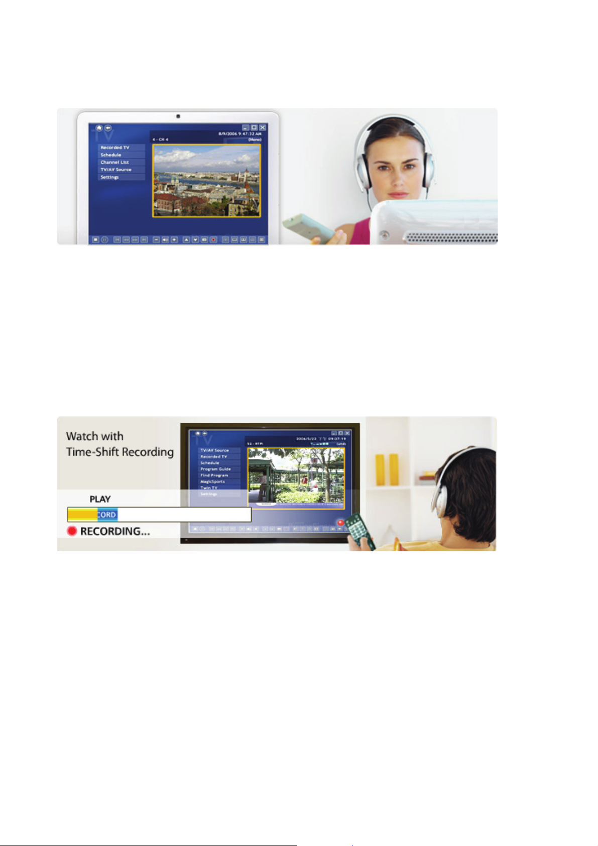
Live TV (and Radio) Recording and Playback
Always Time-Shift Recording lets you shift out of “real time”, watch your programs while TV
Enhance continues to record in the background. You can play, pause, stop, fast forward, and
rewind while your program is still being recorded.
- 54 -

TV Scheduling
TV Enhance lets you check for program information via Internet and Teletext-based Electronic
Program Guides. You can then set your programs to be recorded according to the Electronic
Program Guides schedule. TV Enhance supports up to 99 preset recording times and saves
directly to your hard drive.
TV (and Radio) Surfing
TV Enhance allows the fast selection of TV shows. You cans surf between channels one-by-one,
or jump to your favorite channels using the following features:
• Channel List Manager allows the remaining, enabling, and disabling of channels so that
channel surfing becomes easier and faster.
• Favourite List Management keeps a list of your favorite channels. The order of stations
can be rearranged to facilitate easier channel surfing.
TV Format and Tuner Card Support
• TV Enhance supports the following TV and radio types:
• DVB-T/S (TV and Radio)
• ATSC
• Banquet services from DVB-S or DVB-T
• Analog: NTSC, PAL and SECAM
• FM
TV Card Support
TV Enhance supports a range of TV Tuner cards:
• Hybrid TV-Tuner Card support provides a flexible solution for accessing either digital or
analog TV. Digital TV services include single high-definition or standard-definition channels,
and multiple standard-definition “banquet” services.
• Dual TV-Tuner Card support offers an advanced solution for accessing multiple TV signals
simultaneously. By installing a tuner card in addition to the available bundled card, you can
record one TV channel while viewing another, and view two channels at once using Picturein-Picture mode.
The software varies according to the model and is subject to change without notice (for
specific models only).
- 55 -

McAfee® Personal Firewall*
Proven security that helps prevent hacker attacks.
• Blocks unwanted inbound and outbound Internet traffic.
• Reduces uncertainty about your computer's activities.
• Safeguards your most valuable and irreplaceable information.
• Integrates seamlessly with McAfee
• Updates automatically to protect against new threats.
The Internet has revolutionised the way we communicate, shop and bank, making it easier for
users to reach out to any website or individual computer, at any time. But this freedom also
comes at a price. Each unprotected connection, whether to or from the Internet, leaves your
computer vulnerable to “hacker” attacks.
Proven security that helps prevent hacker attacks, McAfee Personal Firewall safeguards your
financial documents, personal information, photos and online communications, by preventing
unwanted Internet connections to or from your computer. Whether you are on a home
network, broadband or dial-up connection or simply enjoying a hotspot, McAfee Personal
Firewall helps ensure your personal files and information are not compromised.
Product Benefits
• New! Advanced controls for granting an application Internet access, for a specified session
only.
• New! Gaming mode auto-detects whenever you are in “Full-Screen” mode, suppressing
pop-up messages and enhancing your online experience.
• Exclusive! Hackerwatch.org integration links to an anti-hacking database and Worldwide
Hacker Activity Map, offering tips on responding to specific attacks, self-testing tools and
channels to email online authorities of hacker events.
• Intelligent application handling automatically denies outbound Internet access to malicious
applications that might secretly transmit personal data to hackers, while allowing trusted
programs to connect without unnecessary alerts or false alarms.
• Industry standard inbound and outbound blocking provides complete firewall protection.
• Pre-set security levels, ranging from "Open" to "Lockdown", allow you to quickly configure
security settings for your specific Internet experience.
• Auto-updates run silently in the background, ensuring you are always protected from
evolving and emerging security threats.
®
VirusScan® virus detection and removal.
The software varies according to the model and is subject to change without notice (for
specific models only).
- 56 -

McAfee® SecurityCenter*
The McAfee
access to McAfee's world-class managed security products. These services, including a Security
Index and real-time external security alert system, assess, inform and warn you about your
computer's security vulnerability. Each tool quickly evaluates your exposure to security and
Internet-based threats, and then provides recommendations to quickly and securely protect
your computer.
Access to McAfee
1. Double click the McAfee
2. McAfee
3. Then, McAfee
4. Click the “configure” button to configure the setting.
®
SecurityCenter combines a free set of must-have security services with simplified
®
SecurityCenter
®
SecurityCenter main display screen will appear for few seconds.
®
SecurityCenter screen will appear.
®
SecurityCenter icon to launch the application.
Key Features
Redesigned protection status
Easily review your computer's security status, check for updates, and fix potential security
issues.
Continual updates and upgrades
Automatically install daily updates. When a new version of McAfee software is available, you
get it automatically at no charge during your subscription, ensuring that you always have upto-date protection.
Real-time alerting
Security alerts notify you of emergency virus outbreaks and security threats, and provide
response options to remove, neutralise or learn more about the threat.
Convenient protection
A variety of renewal options help keep your McAfee protection current.
Performance Tools
Remove unused files, defragment used files and use system restore to keep your computer
running at peak performance.
Real online help
Get support from McAfee's computer security experts, by Internet chat, e-mail and telephone.
- 57 -

Safe surfing protection
If installed, the McAfee SiteAdvisor browser plug-in helps protect you from spyware, spam,
viruses and online scams by rating Web sites you visit or that appear in your Web search
results. You can view detailed safety ratings that show how a site tested for e-mail practices,
downloads, online affiliations and annoyances such as pop-ups and third-party tracking
cookies.
The software varies according to the model and is subject to change without notice (for
specific models only).
- 58 -

McAfee® VirusScan®*
Proven security that protects against viruses and spyware:
• Protects irreplaceable files, such as family photos and personal financial documents.
• Identifies spyware and adware before they can run on your computer.
• Cleans viruses and virus-like threats automatically.
• Prevents the spread of viruses to other computers.
• Updates automatically to protect against new threats.
From family photos to tax returns, many of the things you value and need most can be found
on your computer. To protect the security of your valuable documents, VirusScan
automatically scans and cleans files, e-mail messages, and downloads, as well as e-mail and
instant message attachments.
Proven security that protects against viruses and spyware, McAfee
®
VirusScan® detects,
blocks, and removes viruses and spyware, that may result in the loss of your irreplaceable
documents, such as digital photos, family movies, and financial spreadsheets, identity theft
and slower computer performance.
Product Benefits
• New! Automatic spyware and adware detection identifies, blocks, and removes identified
potentially unwanted programs, such as spyware and adware, or other programs that
jeopardise your privacy, identity or simply reduce computer performance.
• New! Automated, daily signature updates help keep your computer protected from recently
discovered virus and spyware threats.
• Inline cleaning automatically cleans infections when virus, worm, Trojan, ActiveX control
and Java applet threats are detected.
• Comprehensive, fast and unobtrusive scans identify and remove viruses, Trojans, worms,
unwanted programs, such as spyware and adware, dialers and other malicious virus-like
applications without interrupting your work.
• WormStopper
viruses to friends, family, and co-workers.
• Script-Stopper
• Virus security alerts notify users of potential threats and provides information to avoid
®
monitors suspicious mass-mailing behaviors and prevents the spread of
®
technology prevents new, script-based threats like the "I Love You" virus.
infection.
• 24/7, worldwide virus outbreak monitoring by McAfee's Antivirus Emergency Response
Team (AVERT
immediate antivirus protection and removal solutions to VirusScan
• Always-on protection from viruses, spyware and other Internet threats that may enter your
®
), who continually monitor worldwide virus activities and then provide
®
users.
computer via e-mail, instant message attachments, Internet downloads, and web browsing.
• Auto-updates run silently in the background, ensuring you're always protected from
evolving and emerging security threats.
Access to McAfee
1. Double click the McAfee
2. McAfee
®
Security Center main display screen will appear for few seconds.
3. Then, McAfee
®
VirusScan
®
Security Center screen will appear.
®
®
Security Center icon to launch the application.
4. Click the “scan” button to run the virus scan.
®
The software varies according to the model and is subject to change without notice (for
specific models only).
- 59 -

MDVD Creator Application*
Please take note that the antivirus program might affect the MDVD Creator application. It is
recommended to turn off the spyware and phishing protection (for 1 hour) of the antivirus
program before running MDVD Creator.
As part of our drive to continually improve our products, please visit our “Questions and
Answers” website frequently to obtain the latest information and updates regarding your
system:
http://www.nec-computers-ap.com/faq/vista.asp
One of the important updates is to improve the keyboard’s multimedia buttons function.
The software varies according to the model and is subject to change without notice (for
specific models only).
- 60 -

NMouse Utility Software*
The NMouse Utility Software is a complementary feature of the computer and is optional on
selected models of the mouse. The NMouse Utility provides an easy and convenient way to
operate and navigate your computer.
Some features of the utility include:
• Single click easy zoom support on major applications.
• Right & Left flip support.
• Quick Web Browser control.
• Quick Office application launcher.
• Multimedia playback control and much more.
Easy Zoom
Easy Zoom allows flexible application independence zoom with just a click and scroll. Zoom in
to have a clearer view and zoom out to see more in different applications to fit your needs.
Application independence
Zoom in and out from one application to another according to your needs. Zoom in to read
documents or zoom out to view large collection of image thumbnails. Flexible and time saving!
More Applications
Easy Zoom is supported by various applications including Microsoft
Explorer, Adobe
®
Reader®, desktop icons, image viewers, image editing applications and many
more.
®
Office, Windows® Internet
- 61 -

Easy configuration
Configure the zoom option according to your preferences.
Easy Touch
With NMouse utility software, frequently used buttons can be configured with just a few clicks
away.
Control your multimedia playback, web navigation, office application and office in the same
interface with the easy to use Quick Jump control. No more fiddling around with click after
click.
Web Navigation Control
When clicking on
icon located in the inner circle, an Internet function menu will pop up in
the outer circle:
- 62 -

Functions like WWW, WWW Favorite, WWW Search, Email, WWW Refresh, WWW Back, WWW
Forward, WWW Stop are included.
®
Internet Explorer 5.0 (or above)
WWW
To start your Microsoft
and open the home page you set.
WWW Favorite
WWW Search
Email
WWW Refresh
WWW Back To return the last page you viewed.
WWW Forward To view the next page you’ve viewed before.
WWW Stop
Multimedia Playback Control
To select a web page from your list of favourites.
To gain access to a number of search providers.
To open the default program you use for mail.
Refreshes the current Web page to make sure you have the
latest Web page.
If a page you’re trying to view is taking too long to open,
click this button to stop.
When clicking on
icon located in the inner circle, a Multimedia function menu will pop up
in the outer circle:
Functions like Volume Down, Volume Up, Mute, Previous Track, Next Track, Play/Pause, Stop
and Eject/Close are included.
Volume Down
Volume Up
Controls the volume down or up of your audio output of
speakers.
Mute
Mutes or resumes sound output.
- 63 -

Previous Track
Skip backward to the previous track.
Next Track
Skip forward to the next track.
Play / Pause
Play file in the current track. Press again to pause.
Stop
Stop playing.
Eject / Close
Eject the CD tray. Press again to close tray cover.
Office Application Quick Launch
When clicking on icon located in the inner circle, an Office Function Menu will pop up in the
outer circle:
Functions like Word, Excel, Power Point, Calendar, and Shortcut 1 ~ Shortcut 4 are included.
Word
Opens Microsoft
®
Word.
Excel
Opens Microsoft
®
Excel.
Power Point
Opens Microsoft
®
PowerPoint.
Calendar
Opens "Calendar" function of Microsoft
®
Outlook Express.
This can provide you easy access to the documents and
programs you use most often.
Shortcut 1
Shortcut 2
Shortcut 3
Shortcut 4
Note
The default setting for each Shortcut button is
different. For example, Shortcut 1 is to launch
Windows® accessory program “My Documents”,
Shortcut 2 is to launch "Calculator", Shortcut 3 is
to "Explorer" and Shortcut 4 is to "Notepad".
- 64 -

Office Quick Control
The software varies according to the model and is subject to change without notice (for
specific models only).
- 65 -

Roxio Creator LJ*
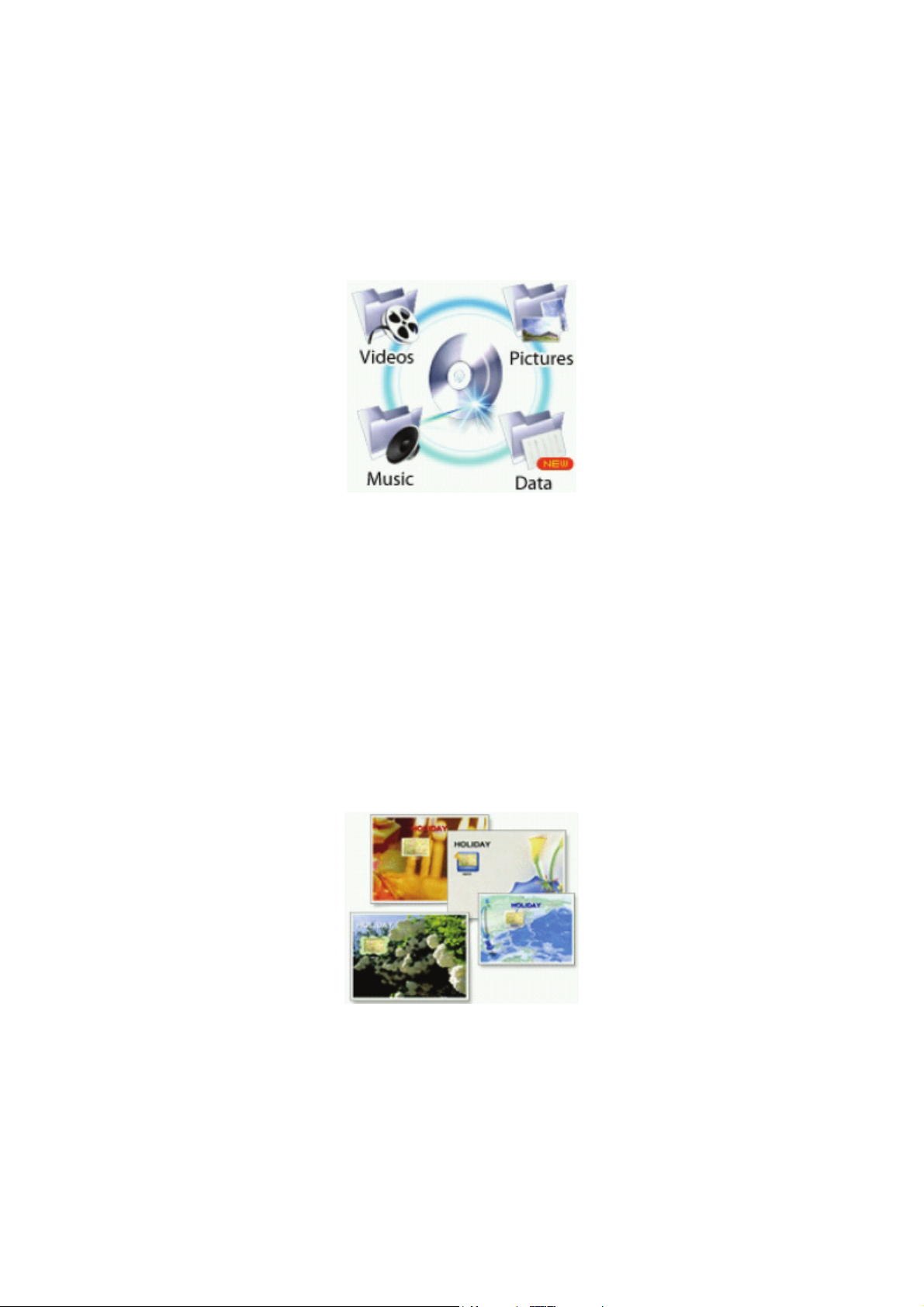
• Burn Data, Audio, Photo and Video CDs & DVDs.
• Backup fast and copy with ease
• Rips CDs Music to Local HDD
• Disc’s Image Creation & Burning
Get the most out of your digital videos, music and photos. Roxio Creator LJ lets you create,
manage and enjoy them the way you want them - where you want them.
Music
• Copy Audio CDs or create your own music mix from several CDs
• Automatically burn hundreds songs across multiple CDs
• Easily rip Audio CDs into WAV, WMA, OGG & FLAC
• Create Jukebox CDs (MP3, WMA, WAV CDs)
• Make custom Audio CDs for your car or home CD Player
Data
• Create mastered data discs.
• Make exact copies of data discs.
• Erase re-writable discs.
• Create bootable discs to recover your system in case of a crash.
Back Up
• Easy Archive back up to CDs, DVDs, external or network drives.
• Make exact copies of discs.
• Create and burn images of CDs and DVDs.
- 66 -

More Features
• Integrated disc labeling for professional results.
• Intelligent drag and drop takes the hassle out of burning.
• Easy-to-use task based interface.
• Tutorial to help you get started.
• Support and product updates.
• Roxio Media Center leads you to the latest update of Roxio’s new products, techniques and
tips.
Advanced Options
• Normalisation and Noise reduction for audio CDs.
• Ability to control burn speeds.
• Control write format including ISO, ISO level 2, Joilet and UDF.
• Record types – Disc-at-once, Track-at-once, open or closed.
• Pre-mastering cache, file date and time.
• Switch between mini mode and full mode interface.
The software varies according to the model and is subject to change without notice (for
specific models only).
- 67 -
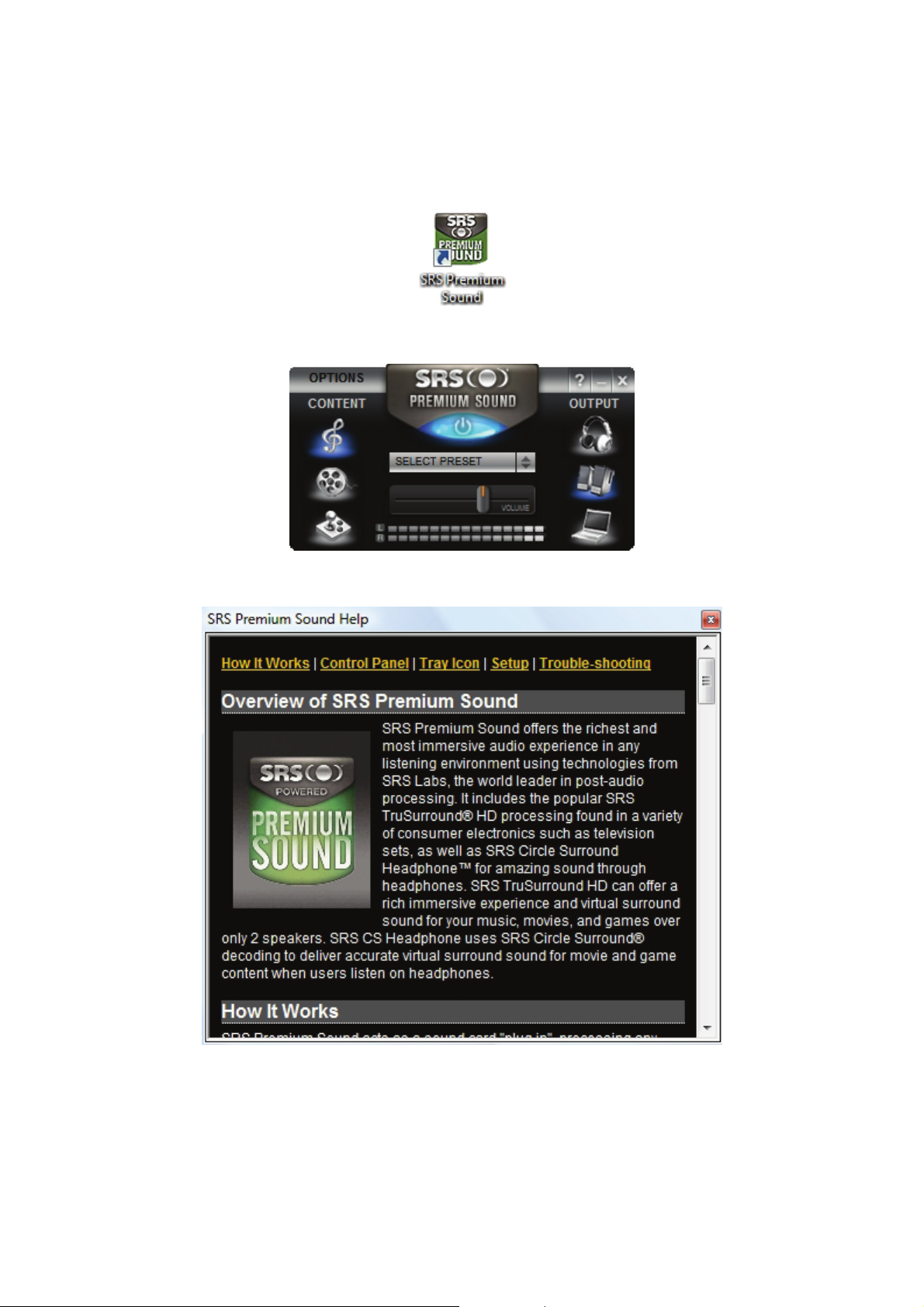
SRS Premium Sound*
SRS Premium Sound from SRS Labs is an audio enhancement technology to enable your
computer with higher quality audio. In order to activate SRS Premium Sound, please double
click on its icon on the Windows
Once activated, it will be automatically loaded every time you start your computer.
For further information, please refer to its on-screen help.
®
desktop.
The software varies according to the model and is subject to change without notice (for
specific models only).
- 68 -

Windows® Aero Theme*
Please take note that availability of certain features in Windows
performance. One of them is the Windows
refresh the Windows
®
Experience Index so that the system performance is updated.
Please refer to the following steps:
®
Aero Theme. As such, we recommend that you
®
depends on system
1. Click Start
then click “Performance Information and Tools” in the Programs list.
2. If this appears, click Refresh Now to update the Windows
, type “performance information and tools” in the Start Search box, and
®
Experience Index. If you are
prompted for an administrator password or confirmation, type the password or click
Continue.
3. After it has refreshed, you will see this: “Your computer has a Windows
®
Experience Index
base score of…”. The value at the end of this statement is your base score. Generally, a
higher score means that your computer will perform better and faster.
1. Click Update my score.
If you are prompted for an administrator password or for confirmation, type the password,
or click Continue.
®
Windows
Should it determine that system performance is sufficient, it will enable Windows
Experience Index assesses the performance of components in the computer.
®
Aero
accordingly. Typically, a minimum base score of 3.0 will automatically enable Windows
on the computer.
The software varies according to the model and is subject to change without notice (for
specific models only).
®
Aero
- 69 -

Introducing BIOS Setup for Windows Vista®
BIOS Setup allows you to view and set system parameters. BIOS Setup also allows you to
set password features that protect your system from unauthorised use.
Use BIOS Setup to:
• set the current time and date;
• customise your operating system to reflect your computer hardware;
• secure your system with a password; and
• balance your performance needs with power conservation.
Entering BIOS Setup
The BIOS Setup can be accessed during the startup or booting of your system. Just press
<F2> when the following prompt appears.
“Press <F2> to run CMOS Setup or <F12> to Boot on Network”
When you press <F2> to enter BIOS Setup, the system interrupts the Power-On Self-Test
(POST) and displays the current complementary metal-oxide semiconductor (CMOS) RAM
settings.
If the system detects an error during POST, it prompts you with a double beep and the
message: "Press <F1> to resume." If you press <F2>, the system enters BIOS Setup
automatically. If you want to fix the error, carefully read the error message that appears
above the prompt (taking notes if you want), and press <F2>. You will see this message if
your system’s CMOS battery (which provides power to maintain system configuration settings)
has become fully discharged.
BIOS Setup Menus
The BIOS Setup features five menus, which are listed on the menu bar at the top of the
screen.
• Main - use this menu for basic system configuration.
• Advanced - use this menu to control system ports and components.
• Security - use this menu to establish system passwords and protect the boot sector of the
hard disk drive against infection by certain virus types.
• Boot - use this menu to set the boot sequence.
• Exit - use this menu to exit BIOS Setup with various save or discard options.
Use the keys listed in the legend bar on the bottom of the Setup menu to make the selections
or exit the current menu.
The exact menu may be different from the system you purchase depending on the mainboard
type.
- 70 -

Updating the BIOS
Please note that these settings are rarely changed by the common user as factory settings are
usually updated, and should only be accessed or changed by an experienced user.
The BIOS is the code transmitted onto your system's Flash ROM. As indicated in this chapter,
you use the BIOS Setup utility to configure your system's software and hardware features.
Only update your system’s BIOS using the update files specific to your computer’s model.
CAUTION
You only need to update the BIOS if significant improvements or fixes have been
made to the current system BIOS. Your authorised dealer or Support Services
representative can help you determine this.
- 71 -

Recovery Information for Windows Vista® only
NEC Recovery Program (from backup partition)
Your computer is supplied with a backup partition on the hard disk drive which contains all the
data you may need in order to restore your configuration as it was when leaving the factory.
This partition occupies about 10 GB of your hard disk drive.
The NEC Recovery Program can restore your computer to the same state as when you
purchased it, while giving you an option to retain all settings and personal data for later
retrieval.
The procedure described below is only applicable if your backup data is stored on your
computer’s hard disk. If you wish to restore your computer using Recovery DVD, please refer
to notes below.
NOTE
This backup partition is hidden.
CAUTION
Before using the NEC Recovery Program it is recommended that you FIRST try fixing
your computer with Windows Vista® System Restore.
System Restore can be used to restore your computer to a previous state when it was
known to function correctly, without affecting your personal data files (such as
documents, browsing history, drawings, favourites, or e-mails).
The NEC Recovery Program Allows Two Types of Recovery
• Full Recovery
Removes all your personal data and restores your computer to its original factory state. By
using this option, all your data will be lost (such as personal documents and settings and
driver updates)
• Partial Recovery
Restores your original operating system and software to their original factory state without
deleting your personal data.
CAUTION
After recovery, all software titles that you have installed on your computer must be
reinstalled before you can use them again. Only the pre-installed titles (such as DVD
Players and CD-writers) will function without additional installation.
- 72 -

IMPORTANT
Please read this section carefully before using NEC Recovery Program!
• Backup your personal files:
Save a copy of your personal documents onto floppy disks, memory cards or high capacity
disks. If you own a CD writer, you can backup larger amounts of data and create your own
archives.
• Return your computer to its original configuration:
1. Remove any additional hardware components (such as sound card, video card and
network card) that you may have added to your computer.
2. Reinstall the original NEC hardware components if you have removed them.
3. Make sure that your keyboard, mouse, monitor and speakers are connected properly (if
applicable to your computer).
4. Disconnect any additional devices that you have connected to your computer (such as
scanners and printers).
Starting the NEC Recovery Program
To launch the NEC Recovery Program:
1. Press the <F8> key upon startup.
2. Then select “Repair Your Computer” at Advanced Boot Options page.
3. Select your preferred keyboard layout. Then click “NEXT” button.
- 73 -
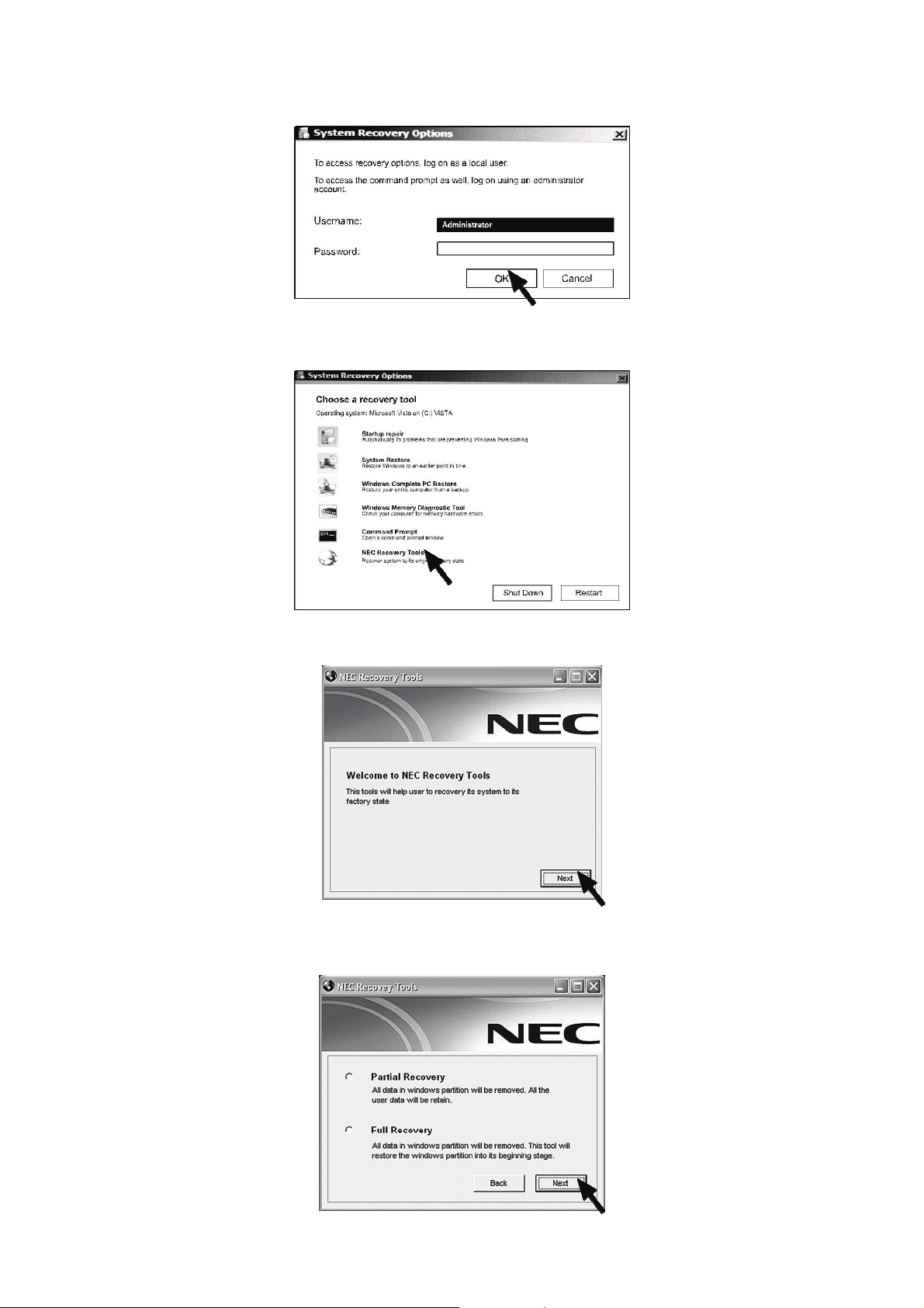
Select “Username” & “Password” (if available). Then click “OK” button.
4.
5. At System Recovery Options, choose “NEC Recovery Tools”.
6. Click “Next” button to continue.
7. Select either “Partial Recovery” or “Full Recovery”. Then click “Next” button to
continue.
- 74 -

Click “OK” button to continue.
8.
9. Click “Start” button to start the recovery process.
CAUTION
Please wait a while for the recovery process to be completed.
10. The NEC Recovery tools application will close automatically after the recovery is completed.
11. Finally you have to restart your computer by clicking the “Restart” button at System
Recovery Options.
If You Wish to Perform a Full Recovery:
CAUTION
Full Recovery will remove all your personal data and restore your computer to its
original factory state.
Select “Full Recovery” and click on “Next”. Then follow the on-screen instructions to
complete the recovery.
- 75 -

If You Wish to Perform a Partial Recovery:
1. Select “Partial Recovery” and click on “Next”.
2. Follow the on-screen instructions to complete the recovery.
Note
There may be a delay the first time Windows® restarts after the recovery process. This
delay depends on the amount of data that must be retrieved from the selected
account.
3. After the Partial Recovery process has been completed and if you have used default
Windows
• Your Documents and Settings:
C:\user\[Previous User Name]\...
• Applications:
C:\Program Files\[Application Name]\...
• Other files:
You can use the Windows
4. Finally, reinstall software titles you wish to use.
®
settings, you may retrieve your data in the following locations:
®
Search Engine to find other files.
CAUTION
You should consider deleting items on the desktop and in the Start Menu, and also
folders for applications you no longer wish to use.
DO NOT delete folders for software that you did not originally install yourself – they
may contain important Windows® files.
- 76 -

FREQUENTLY ASKED QUESTIONS (FAQ)
• Start-up
1. My computer does not start.
2. Upon startup, my computer displays unusual commands.
3. Upon startup, my computer emits a continuous beeping sound.
• Recovery and Diagnosis
4. What are the tools on my computer?
5. How to use the Windows Vista
®
System Restore?
• Keyboard and Mouse
6. My keyboard does not work.
7. My mouse does not work.
• Sound
8. My computer has no sound.
• Internet
9. I cannot connect to the Internet.
10. I cannot send or receive e-mails.
11. I seem to have a virus on my computer.
• Printer
12. My printer does not work.
- 77 -

FAQ: Start-up
1. My computer does not start
Possible cause Possible solutions
You have not turned on your system
correctly.
Make sure that you have switched on your
computer.
No power is supplied to your computer
devices.
i. Check the power cord connections between
your computer and the power outlets.
ii. Check the power cords.
If you are using a computer:
Unplug the computer's power cord from the wall socket and depress the power button for at
least ten seconds. Then release it, connect the power cord again and press the power button
to turn on your computer. Before you connect or disconnect the power cord at the back of the
computer, please ensure that the power plug is disconnected from the wall outlet.
2. Upon startup, my computer displays unusual commands.
My computer says “Non system disk” or “Invalid system disk”.
Possible cause Possible solutions
The system files on your hard disk drive
are damaged and your computer can no
This may be caused by a virus: run a virus scan
after successful restoration of your computer.
longer read them to startup.
3. Upon startup, my computer emits a continuous beeping sound.
Possible cause Possible solutions
There is a keyboard or mouse detection
Check your keyboard and mouse connection.
failure.
There is a key stuck on the keyboard or a
button on the mouse is stuck.
i. Follow the steps to switch your computer OFF.
ii. Press all the keys of your keyboard to ensure
that no key is stuck.
iii. Tap the mouse buttons to ensure that none of
them are stuck.
iv. Switch your computer ON again.
- 78 -

FAQ: Recovery and Diagnosis
4. What are the tools on my computer?
Utilities
Your computer contains several powerful recovery tools especially designed for your computer.
Please refer to the Recovery Guide that is available on selected models only.
WARNING
We strongly recommend that you read all instructions before you use any of these
utilities.
Please read this section carefully before using the Recovery Program!
• Backup your personal files
Save a copy of your personal documents onto floppy disks, memory cards or high capacity
disks. If you own a CD writer, you can backup larger amounts of data and create your own
archives.
• Return your computer to its original configuration
i. Remove any additional hardware components (such as sound card, video card or
network card) that you may have added to your computer.
ii. Reinstall the original NEC hardware components if you have removed them.
5. How to use Windows Vista® System Restore?
System Restore monitors the changes to your computer and automatically creates restore
points to revert to a previous time if necessary. It can undo harmful changes to your computer
and restore its settings and performance, while saving your personal documents and e-mails.
When you restore your computer you will need to reinstall any programs you installed after the
restore point was created. These programs will not work until you do this. System Restore
does not uninstall programs.
To do this, you should use Programs and Features in Control Panel (Start button
Control Panel, click Programs).
, click
- 79 -
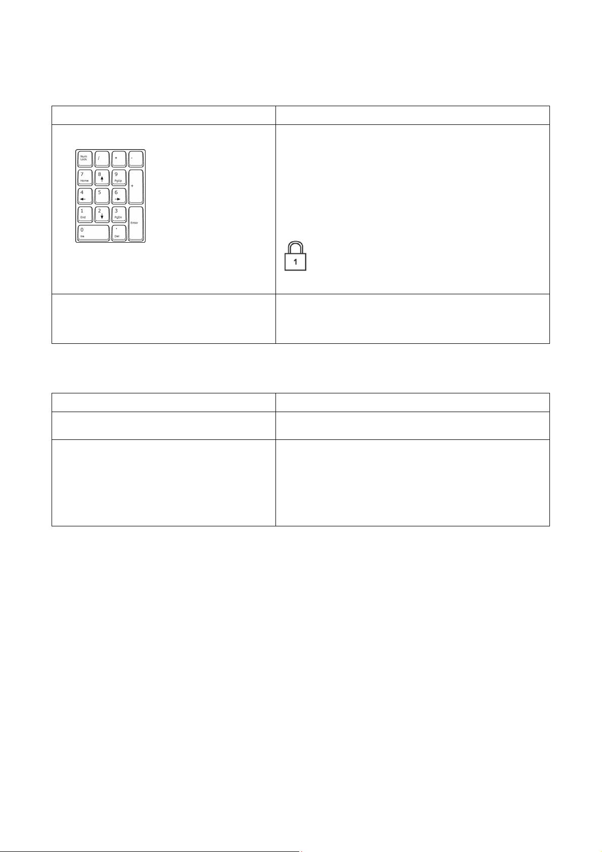
FAQ: Keyboard and Mouse
6. My keyboard does not work.
Possible cause Possible solutions
The Numeric pad is disabled.
When the Num Lock key is active, the Numeric
pad can be used to enter numbers, like the
keyboard of a calculator.
When the Num Lock key is not activated the
keypad either functions as a second set of cursor
keys (on “full-sized” keyboards), or they revert to
normal letter keys (on certain compact keyboards).
On some computers, the Num Lock icon
is shown in the Notification Area on your
taskbar.
Your keyboard is not properly connected. i. Switch your computer OFF.
ii. Disconnect then reconnect the keyboard
properly.
iii. Switch your computer ON.
7. My mouse does not work.
Possible cause Possible solutions
Your mouse is not properly connected. Follow the same procedure as for checking
keyboard connection.
The controller properties are not properly
set up.
If the pointer moves with difficulty, too quickly or
too slowly, or if double clicking does not work all
the time, try to adjust the properties of your
controller. To access, Click the “Start” button,
select “Control Panel” then select the “Mouse” icon.
From here you can adjust various properties of
your mouse.
- 80 -

FAQ: Sound
8. My computer has no sound
Possible cause Possible solutions
The speaker volume may be set too low. Adjust the volume controls (either on your
speakers, keyboard, or on the computer).
Your computer's volume control settings
may need adjusting.
Double-click on the speaker icon in the Notification
Area on your taskbar.
Your computer will not play audio CDs.
• Make sure that your computer sound is set up properly.
• Make sure that the disc’s surface is clean and scratch free.
Note
Make sure the CD is not copy-protected. Some audio CDs include a copy protection
mechanism to avoid illegal copying. This mechanism prevents the CDs from being
played or copied on a computer. In this case, playback is only possible on
conventional CD or DVD players.
- 81 -

FAQ: Internet
9. I cannot connect to the Internet.
In order to get the best possible Internet connection from your computer and phone line,
ensure that you:
• Always connect to a grounded power socket.
• Avoid using telephone extension cables (this degrades the signal quality).
Possible cause Possible solutions
Your account details have not been
released yet.
You entered an incorrect user name
and/or password.
i. Immediately after you have performed your
online subscription with an Internet Service
Provider (ISP), it is recommended that you
restart your computer to complete the Internet
setup process.
ii. The first time you use your Internet connection
your account may not be accepted
immediately. Certain ISPs require a short setup
period to process your account details. Please
wait 30 minutes before you try to connect to
their services again.
i. Check your user ID and password. Retype them
if necessary.
ii. Check exact spelling (upper and lower case, or
any punctuation).
iii. Check the login and setup information given to
you by your ISP.
The server you are trying to connect is
out of order.
The settings in your Internet browser or
your e-mail program may have been
changed, or your internet connection
settings may have been changed.
Your account with your Internet Service
Provider has been terminated or your ISP
server is unavailable.
You have performed a complete recovery
using the NEC Recovery Program.
10. I cannot send or receive e-mails.
Possible cause Possible solutions
You are not connected. To send and receive e-mails, you need to be
Your ISP or that of your recipient is
having technical difficulties.
Using several ISPs or e-mail accounts
can cause problems.
I have sent a message but I get an error
message in reply.
Check with your ISP whether the service is
available.
When you subscribe, your ISP usually provides
connection details (such as user name, password,
server phone number and e-mail address). Check
these details and restore your Internet settings,
following the procedures given by your ISP.
Contact your ISP and check the access conditions
to their Internet server.
If you subscribed to one of the ISPs offered by NEC
try to reinstall the Internet service.
connected to the Internet.
Try again later or check with your ISP whether the
service is available.
Check that you have selected the correct Internet
Service Provider (ISP) for the account you are
attempting to use. An ISP provides you Internet
access, so different providers have different settings.
i. Check the spelling of your recipient's e-mail
address.
ii. Check with your recipient that the e-mail
address is still valid.
- 82 -

11. I seem to have a virus on my computer.
If you suspect your computer has been infected by a virus, you should first perform a virus
check to try to fix it and always observe some basic safe computing guidelines:
i. Run an antivirus program
NEC has installed antivirus software on your computer. This program checks your computer
for viruses and will delete any suspicious file. Run this program regularly and make sure
you update it on the Internet and get the latest protection against malicious viruses.
Note
NEC guarantees that your computer is 100% virus free at the time of purchase and
does not cover damages due to viruses.
ii. Use a Personal Firewall
A firewall is a security system designed to prevent unauthorised access to or from a private
network. It acts as a shield to block dangerous Internet threats and keep the information
on your computer safe and private.
iii. DO NOT OPEN suspicious e-mail attachments
To be completely safe, scan the attachment with your antivirus software before you open
it. Delete any suspicious message from your Inbox and go into the Deleted Mail folder to
permanently remove it.
- 83 -
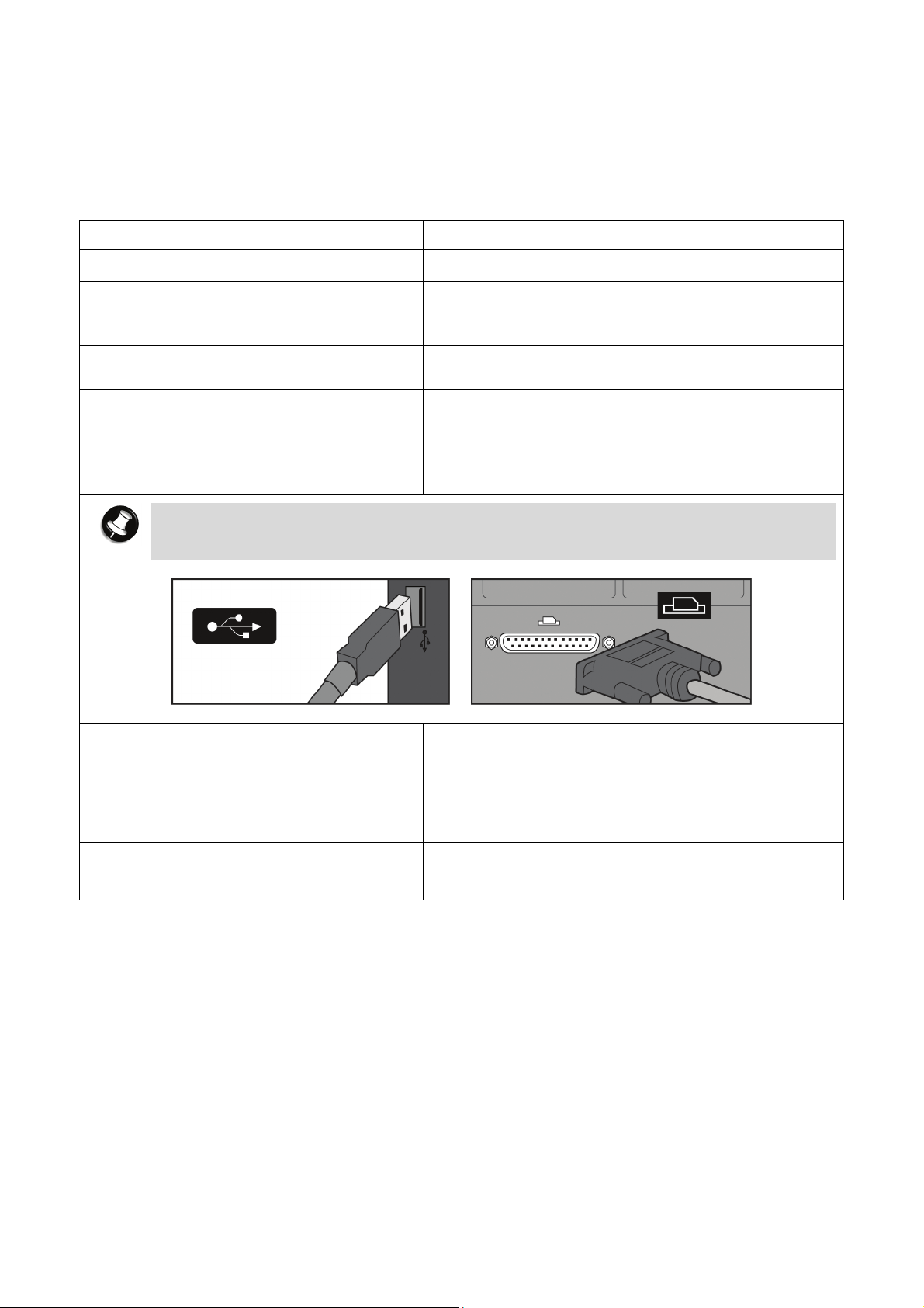
FAQ: Printer
12. My printer does not work.
The guidelines below cover the most common types of problems encountered with printers.
Please read your printer’s manual (if any) for specific instructions. Should you need further
assistance, please contact the manufacturer of your printer.
Possible cause Possible solutions
The printer is OFF. Switch the printer ON.
The printer is offline. Press the printer’s online button.
The printer is out of paper. Add paper.
The paper is jammed. Refer to your printer’s user’s guide for information
about clearing paper jams.
The printer has generated an error
message.
The printer is not connected properly.
Refer to your printer’s manual for information
about resolving error messages.
Check that the cables are securely connected to
the printer and computer. Use a grounded AC
power outlet (or power strip).
Note
Remember to shut down your computer and printer before disconnecting or
reconnecting any cables (even if your printer uses a Hot-pluggable type connection).
No power is supplied to the printer. i. Plug the printer into a different wall socket.
ii. Restart the computer and printer again and try
printing to determine if the previous socket
was faulty.
The printer cable is damaged. If you have another printer cable, try using it to
determine if your printer cable is faulty.
Your printer is not installed correctly in
Windows
®
.
Try to reinstall your printer. See your printer’s
manual for information about installing the printer
in Windows
®
.
- 84 -

Setting Up a Healthy Work Environment
•
Arrange Your Equipment
o Your Chair
o Your Desk
o Your Input Devices
o Your Screen
• Reducing the Risk of Injuries
o Vary Your Workday
o Practise Some Stretching Exercises
• Potential Medical Conditions
o Repetitive Strain Injury
o Pre-Existing Conditions and Psychosocial Factors
o Epilepsy Warning
- 85 -
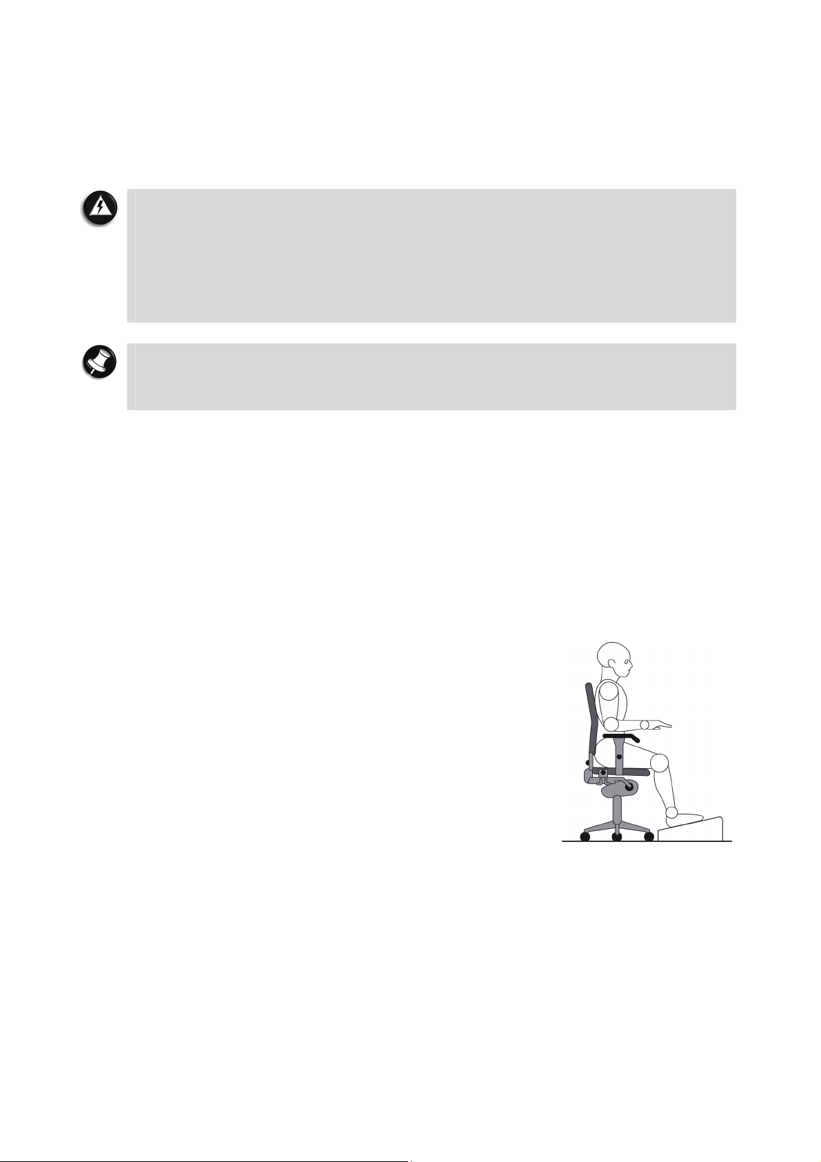
Arrange Your Equipment
You will find below explanations on how to set up your computer to fit your physical needs.
This information is based on ergonomics - the science of making the workplace fit the needs of
the worker.
WARNING
Prolonged or improper use of a computer workstation may pose a risk of serious
injury. To reduce your risk of injury, set up and use your computer in the manner
described below. Please note that some people are more susceptible to developing
these disorders due to pre-existing conditions or psychosocial factors (see section on
“Pre-existing Conditions and Psychosocial Factors”), and that precautions can be
taken in order to prevent physical discomfort (see section on “Reducing the Risk of
Injuries”).
Note
To increase your comfort and safety when using your computer as your primary
computer system at your home or office, note the following recommendations:
• use a separate, external keyboard attached to your computer.
Arrange your equipment so that you can work in a natural and relaxed position. Place items
that you use frequently within easy reach. Adjust your workstation set-up to the proper height
(as described below) by lowering the table or stand that holds your computer equipment or
raising the seat height of your chair. Position your computer directly in front of you for
increased safety and comfort.
Your Chair
Your chair should be adjustable and stable. Vary your posture throughout the day.
Check the following:
• Keep your body in a relaxed yet upright position. The
backrest of Use the entire seat and backrest to support your
body. Tilt the backrest slightly (90° to 105°). The angle
formed by your thighs and back should be 90° or more.
• Your seat depth should allow your lower back to comfortably
contact the backrest. Make sure that the backs of your
lower legs do not press against the front of the chair.
• Extend your lower legs slightly so that the angle between
your thighs and lower legs is 90° or more.
• Place your feet flat on the floor. Only use a footrest when
attempts to adjust your chair and workstation fail to keep
your feet flat.
• Be sure that you have adequate clearance between the top of your thighs and the
underside of your workstation.
• Use armrests or forearm supports to support your forearms. If adjustable, the armrests
or forearm supports should initially be lowered while all the other adjustments
discussed in this section are made. Once all these adjustments are completed, raise the
armrests or adjust the forearm supports until they touch the forearms and allow the
shoulder muscles to relax.
- 86 -

Your Desk
There is no specific height recommended for your desk. This can vary between 60 and 70 cm,
depending upon your size. The standard workaround is that it should be at approximately your
elbow height.
The computer should be clean and organised in such a way that frequently used objects are
close enough without excessive reaching. If you use a document holder, it should be placed at
approximately the same height as the screen and at the same distance from the eyes to
prevent frequent eye shifts.
The area underneath the desk should be clean to accommodate your legs and allow for
stretching.
Your Input Devices
Note the following points when positioning your computer or any external input
devices.
• Position your keyboard directly in front of you. Avoid reaching when using your keyboard or
mouse.
• If you use a mouse, position it at the same height as the keyboard and next to the
keyboard. Keep your wrists straight and use your entire arm when moving a mouse. Do not
grasp the mouse tightly. Grasp the mouse lightly and loosely.
• Adjust the keyboard height so that your elbows are near your body and your forearms are
parallel to the floor, with your forearms resting on either armrests or forearm supports, in
the manner described previously. If you do not have armrests or forearm supports, your
upper arms should hang comfortably at your sides.
• Adjust the keyboard slope so that your wrists are straight while you are typing.
• Type with your hands and wrists floating above the keyboard. Use a wrist pad only to rest
your wrists between typing. Avoid resting your wrists on sharp edges.
• Type with your wrists straight. Instead of twisting your wrists sideways to press hard-toreach keys, move your whole arm. Keep from bending your wrists, hands, or fingers
sideways.
• Press the keys gently; do not bang them. Keep your shoulders, arms, hands and fingers
relaxed.
Your Screen
Correct placement and adjustment of the screen can reduce eye, shoulder, and neck fatigue.
Check the following when you position the screen.
• Adjust the height of your screen so that the top of the screen is at or slightly below eye
level. Your eyes should look slightly downward when viewing the middle of the screen.
• Position your screen no closer than 30 cm and no further away than 75 cm from your eyes.
The optimal distance is between 35 cm and 45 cm.
• Rest your eyes periodically by focusing on an object at least 6 metres away. Blink often.
• Position the screen at a 90° angle to windows and other light sources to minimise glare and
reflections.
• If reflected light makes it hard for you to view your screen, use an anti-glare filter.
• Clean your screen regularly. Use a lint-free, non-abrasive cloth and a non-alcohol, neutral,
non-abrasive cleaning solution or glass cleaner to minimise dust.
• Adjust the screen brightness and contrast controls to enhance readability.
• Use a document holder placed close to the screen.
- 87 -

• Position whatever you are looking at most of the time (the screen or reference material)
directly in front of you to minimise turning your head while you are typing.
• Get regular eye check-ups.
Reducing The Risk of Injuries
Prolonged or improper use of a computer workstation may pose a risk of serious injury. To
reduce your risk of injury, set up and use your computer in the manner described in the
section on “Arrange Your Equipment”. Please note that some people are more susceptible to
developing these disorders due to pre-existing conditions or psychosocial factors (see the
section on “Pre-existing Conditions and Psychosocial Factors”).
The precautions described below can however be taken in order to prevent physical
discomfort.
Vary Your Workday
If you use your computer for prolonged periods, follow these instructions.
• Vary your tasks throughout the day.
• Take frequent short breaks that involve walking, standing, and stretching. During these
breaks, stretch muscles and joints that were in one position for an extended period of time
(refer to the section on “Stretching Exercises”). Relax muscles and joints that were active.
• Use a timer or reminder software to remind you to take breaks.
• To enhance blood circulation, alter your sitting posture periodically and keep your hands
and wrists warm.
Practise Some Stretching Exercises
The daily exercises described below can be very effective in stopping Repetitive Strain Injury
development or in minimising its effects. They can easily be carried out behind your computer.
• Bend wrists, stretch and close fingers - stretch your arms and wrists with closed
fingers; keep this pose for 8 seconds. Repeat the exercise 3 times. You can repeat the
same exercise with your finger stretched.
• Lift shoulders - lift your shoulders straight up, hold that pose for 8 seconds and repeat
the exercise 3 times.
• Rotate shoulders - rotate both your shoulders clockwise and counter-clockwise for
8 seconds. Repeat this exercise 3 times.
• Stretch neck and shoulders - bend your head to the left, right, front and back. Keep
each position for 8 seconds. Repeat this exercise 3 times.
• Stretch the flexors - fold your hands into a praying position; palms flat against each
other in front of your chest. Pull your hands gently downwards along your chest towards
the stomach, keeping the elbows in the same position. Repeat the exercise 3 times and
keep the pose for 8 seconds.
• Stretch the extensors - stretch your arm straight forward. Rotate your wrist 90 degrees
up towards you and keep your thumb down, so that your other fingers are all pointing
upwards (your hand should look like it is held out, telling someone to stop). Grab your four
fingers pointing upwards with your other hand, and gently pull them towards you, while
keeping your arm straightened. Hold this pose for 8 seconds and repeat this exercise
3 times.
- 88 -

Potential Medical Conditions
Computers are used everywhere. More and more people sit in front of computers for longer
periods of time. Some nerve, tendon and muscle disorders (musculoskeletal disorders) may be
associated with repetitive activities, improper work environments, and incorrect working
habits. Examples of musculoskeletal disorders that may be associated with certain forms of
repetitive activities include: carpal tunnel syndrome, tendinitis, tenosynovitis, de Quervain's
tenosynovitis and trigger finger, as well as other nerve, tendon and muscle disorders.
WARNING
Prolonged or improper use of a computer workstation may pose a risk of serious
injury. To reduce your risk of injury, set up and use your computer in the manner
described in the section on “Arrange your Equipment”. Please note that precautions
can be taken in order to prevent physical discomfort (see section on “Reducing the
Risk of Injuries”).
Although some studies have shown an association between increasing hours of keyboard use
and the development of some musculoskeletal disorders, it is still unclear whether working at a
computer causes such disorders. Some doctors believe that using the keyboard and mouse
may aggravate existing musculoskeletal disorders.
Note
Contact a doctor if you experience pain, tenderness, swelling, burning, cramping,
stiffness, throbbing, weakness, soreness, tingling and/or numbness in the hands,
wrists, arms, shoulders, neck, back and/or legs.
Repetitive Strain Injury
Repetitive Strain Injury is caused by a constant tension of the muscles in your arms and by
making the same repetitive movements with fingers, wrist and elbow when controlling the
mouse. The symptoms of RSI are pain and stiffness in neck, shoulders, arms, wrists and
hands. Other symptoms are cramps, tingling and exhaustion in these areas.
The Three Stages of Repetitive Strain Injury
Real RSI-pain implies that the problems have persisted for a longer period of time, normally
for a minimum of three months. The development can be divided into three stages:
• Stiffness, numbness, irritation, sometimes in combination with light or sharp pains. These
problems disappear, but return when similar work is done.
• The problems do not disappear overnight. Continuous light pain, also after a period of rest.
After a longer period of rest (holidays) the pain does go away, but returns easily when
similar work is done.
• Continuous pain often combined with reduced strength and less accurate control. At work,
the pain intensifies. When rested, the pain remains.
Pre-Existing Conditions and Psychosocial Factors
Pre-existing conditions that may cause or make some people more susceptible to
musculoskeletal disorders include the following: hereditary factors, vascular disorders, obesity,
nutritional deficiencies such as Vitamin B deficiency, endocrine disorders such as diabetes,
hormonal imbalances, connective tissue disorders such as arthritis, prior trauma to the hands,
wrists, arms, shoulders, neck, back, or legs, prior musculoskeletal disorders, aging, fluid
retention due to pregnancy, poor physical conditioning, dietary habits and other conditions.
Psychosocial factors associated with these disorders include: workplace stress, poor job
satisfaction, lack of support by management and/or lack of control over one's work.
- 89 -

Contact a doctor if you experience pain, tenderness, swelling, burning, cramp, stiffness,
throbbing, weakness, soreness, tingling and/or numbness in the hands, wrists, arms,
shoulders, neck, back, and/or legs.
Epilepsy Warning
Some people are susceptible to epileptic seizures or loss of consciousness when exposed to
certain flashing lights or light patterns in daily life. Such people may have a seizure while
watching television images or playing certain games. This may happen even if the person has
no medical history of epilepsy or has never had any epileptic seizures.
If you or anyone in your family has ever had symptoms related to epilepsy (seizures or loss of
consciousness) when exposed to flashing lights, consult your doctor prior to playing games
with such features. We advise that parents monitor the use of games by their children. If you
or your child experience any of the following symptoms such as : dizziness, blurred vision, eye
or muscle twitches, loss of consciousness, disorientation, any involuntary movement or
convulsion while playing a game, IMMEDIATELY discontinue use and consult your doctor.
- 90 -

Safety Notices
• Cleaning Your Computer
• Modem
• Modifications to the Product
• Radio Frequency Interference Statement
• Connections and Remote Earth
• Power Supply and Cables
• Laser Compliance Statement
• Thunderstorm Warning
• Radio-communication Regulation (if applicable)
• Precautions When Using TV Tuner With External
Antenna
• Additional Notices
• Electrostatic Discharge (ESD) and ESD Protection
• Computer Environment
• Product Storage Environment Guidelines
Safety Guidelines for Battery Usage
•
- 91 -

Cleaning Your Computer
Always unplug your computer from the power outlet before cleaning it. Do not use liquid or
aerosol cleaners, use a damp cloth instead. Never spray any cleaning product directly on to the
screen.
If you spill liquid on your computer or any device attached to it, switch it off immediately,
unplug the power cord and make sure it is completely dry before switching it on again. Wait
overnight if necessary.
Modem
Only use a modem that has been approved by the national authority of the country in which
the product is sold. Technically and in most cases, the same modem should work in all
countries. Nevertheless, be advised that some countries might have strict laws which forbid
the modem from being used before it is technically approved. Kindly check this information
with your dealer or get an approved modem as a replacement.
Modifications to the Product
Radio Frequency Interference
The manufacturer is not responsible for any radio or TV interference caused by unauthorised
modifications to this equipment.
Safety Warning
The manufacturer is not responsible for any safety hazards caused by unauthorised
modifications to this equipment.
Radio Frequency Interference Statement
WARNING
Changes or modifications to this unit not expressly approved by the party
responsible for compliance could void the user's authority to operate the equipment.
The manufacturer is not responsible for any radio or TV interference caused by
There is no guarantee, however, that interference will not occur in a particular installation. If
this equipment does cause harmful interference to the radio or television reception, which can
be determined by switching the equipment on and off to check its effect on reception, the user
is encouraged to try to correct the interference by applying one or more of the following
measures:
• Reorient or relocate the receiving antenna.
• Increase the distance between the equipment and receiver.
• Connect the equipment to an AC power outlet on a circuit separate from the one to which
To meet the CISPR22 Standard, shielded cables and power cords are required when connecting
this device to a personal computer or other Class B certified devices.
unauthorised modifications to this equipment.
Note
This is a Class B digital device. This equipment has been tested and found to comply
within the limits for a Class B digital device, pursuant to the CISPR22 Standard
(CISPR is the acronym for the French name of the International Special Committee
on Radio Interference, IEC). These limits are designed to provide reasonable
protection against harmful interference in a residential installation. This equipment
generates, uses and can radiate radio-frequency energy. If not installed and used in
accordance with the instructions, it may cause harmful interference to radio
communications.
the receiver is connected.
- 92 -

Connections and Remote Earth
Protected Extra Low Voltage (PELV)
To ensure the extra-low voltage integrity of the equipment, only connect equipment with
mains-protected, electrically-compatible circuits to the external ports.
Safety Extra Low Voltage (SELV)
Each input and output of this product is classified as Safety Extra Low Voltage, except the
modem, which is classified as TNV-3.
Remote Earth
To prevent electrical shocks, connect all local (individual office) computers and computer support
equipment to the same electrical circuit of the building's wiring. If you are unsure, check the
building's wiring to avoid remote earth conditions.
Building Supply
Only connect the equipment to a building supply that is in accordance with current wiring
regulations in your country.
- 93 -

Power Supply and Cables
Your computer may come with more than one type of power cord.
Please note the following identifications to ensure that you are using the right power cord in
order to avoid electrical shock hazards.
This power cord plug is suitable for use in Malaysia,
Singapore, Hong Kong, Bangladesh and Maldives.
This power cord plug is suitable for use in Thailand and
Philippines.
This power cord plug is ONLY suitable for use in Indonesia,
Mongolia and most countries in Europe except
United Kingdom.
This power cord plug is suitable for use in Australia and
New Zealand. The live and neutral pins have insulation as
an extra safety precaution.
WARNING
Failure to use the correct power cords may result in electrical shock.
Power Supply
The power supply socket-inlet and socket-outlet (if equipped) are classified as Hazardous
Voltage.
You must unplug the power supply cord to disconnect the equipment from the power supply.
For this purpose, the socket-outlet should be installed as close to the equipment as possible
and should be easily accessible.
In Europe, before plugging the power cord into an AC power outlet, check that the voltage
selector switch of the computer's power supply (if available) is in position “230 V”. In the
U.S.A. and Canada, before plugging the power cord into an AC power outlet, check that the
voltage selector switch of the computer's power supply (if available) is in position “115 V”. In
Asia, before plugging the power cord into an AC power outlet, check that the voltage selector
switch of the computer's power supply (if available) is in position “230 V”.
Under no circumstances should the user attempt to disassemble the power supply. The power
supply has no user-replaceable parts. The power supply has hazardous voltages that can cause
serious personal injury.
A defective power supply must be immediately returned to your dealer.
- 94 -

Power Cables
This equipment requires a 3-wire, grounded power cord. The cord length must not exceed 2.5
metres. To prevent electrical hazards, do not remove or disable the ground contact on the
power cord. Replace the power cord if it gets damaged. Contact your dealer for an exact
replacement. In Europe, the plug must be rated for 250 VAC, 10 amp minimum. In the U.S.A.
and Canada, the plug must be rated for 125 VAC, 10 amp minimum. The plug must display an
international agency approval marking. The cord must be suitable for use in your country.
Consult your dealer or the local electrical authorities if you are unsure of the type of power
cord to use in your country.
Cables
Please make sure that cables are not strained and that there is no risk of people walking or
tripping over them. Also make sure that other devices do not place stress on the cables. Make
sure that power cords are connected to a grounded electrical outlet. The power outlet should
be easily accessible and as close to the computer as possible. Do not overload any power
outlet with too many adapters.
The EMC performance of the system is guaranteed only if the cable and interface use efficient
shielding.
The use of shielded interface cable is required for USB, IEEE 1394, serial, printer, game,
analogue or digital audio/video, Ethernet LAN, PS/2, TV or FM antennas, and generally all high
speeds cable interfaces.
Only Ethernet LAN or RTC modem cables can have lengths exceeding 3 metres.
For Ethernet LAN cable, use FTP shielded cables only (Cat ≥ 5).
Heat build-up
The AC adaptor and the underside of the computer can become hot after prolonged use.
Sustained physical contact with either should be avoided.
Laser Compliance Statement
The optical devices are tested and certified to be compliant with the International Electrotechnical Commission IEC825-1 and the European Norm EN60825-1 and the EN60825-2
regulations for Class 1 laser products.
Class 1 laser products are not considered hazardous. The optical devices are designed so that
there is no risk of human exposure to laser radiation above a Class 1 level during normal
operation or prescribed maintenance conditions.
The optical devices installed in your computer are designed for use solely as components of
such electronic products and therefore do not comply with the appropriate requirements of
Code of Federal Regulation Sec. 1040.10 and Sec. 1040.11 for COMPLETE laser products.
Thunderstorm Warning
• This warning is only applicable if the product you purchased has a modem and/or TV- tuner.
Similar precautions should be taken if you are connecting a modem or TV- tuner to the
product.
• It is advisable to connect a telephone cable and/or an antenna cable to wall plugs which are
equipped with lightning-surge protection. If this is unavailable, then avoid connecting both
cables during thunderstorms.
• Always disconnect the telephone cable and/or the antenna cable even though the product is
shut down or in standby mode.
- 95 -
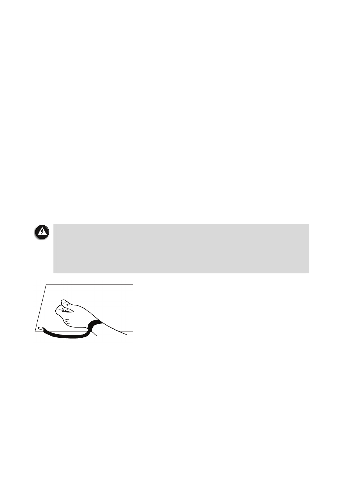
Radio-communication Regulation (if applicable)
Specific regulations apply when using wireless radio-communication products.
Precautions When Using TV Tuner with External Antenna
• The circuit of cable distribution system under consideration is TNV-1 circuit.
• The common sides or earthed side of the circuit are connected to the screen of the coaxial
cable through an antenna connector of tuner and to all accessible parts and circuits (SELV
and accessible metal parts).
• The screen of the coaxial cable is intended to be connected to earth in the building
installation.
Additional Notices
Each input or output of this product is classified as Safety Extra Low Voltage (SELV).
Electrostatic Discharge (ESD) and ESD Protection
WARNING
Electrostatic Discharge (ESD) can damage disk drives, cards, memory modules and
other parts. We recommend that you carry out all procedures in this guide only at an
ESD-workstation. If one is not available, provide some ESD protection by wearing an
antistatic wrist strap attached to any unpainted metal surface when handling parts.
If you do not have one, discharge static electricity from yourself and your clothing
by touching a nearby metal surface before handling any internal components.
Computer Environment
Make sure your computer’s environment is free from dust, dampness or direct sunlight. Place
your computer away from sources of heat, such as radiators, or any device producing heat
(e.g., amplifiers). Also ensure your computer is away from magnetic fields or any device
generating static electricity. Do not place your computer on a carpet or any other surface that
may have an electrical charge. Cellular phones can cause interference with the audio devices
of your computer. Make sure you keep mobile phones at least 30 centimetres away from your
computer. To keep your computer running smoothly, please remember the following:
• If you are new to computing, we recommend taking a computer-training course before
using your computer.
- 96 -

Always save your work and make regular backup copies of your documents on rewritable
•
media (such as rewritable discs). In the event of a major computer failure, you can lose all
your personal data unless you make personal backups.
• To protect your computer from viruses, perform a virus check before opening a file on a
floppy, received by e-mail, or downloaded from the Internet. Your anti-virus program can
perform these checks automatically. Regularly scan your hard disk drive for viruses and
delete them if any are found. Check your anti-virus software website in order to be
updated on the latest viruses.
• To save disk space and optimise your computer’s performance, use the system tools
included with Windows, such as Disk cleanup or Defragmenter, on a regular basis.
• Never switch off your computer if one of the drives is still running (check that all drive
indicator lights are off).
• If your computer has ventilation holes at the bottom side of casing, do not place it on a
carpet or other surfaces which may block the ventilation holes.
• The computer you have purchased may be supplied with a pair of stands. Should you want
to use your computer in a tower orientation, please assemble the stand according to the
user guide provided with it. This will prevent the computer from toppling or falling.
Product Storage Environment Guidelines
1. When the product is in use (or started up):
• This product is best used in temperatures from 15ºC to 25ºC.
• Avoid placing the product in a dusty environment as excessive dust might be sucked
into the machine body, reducing its cooling efficiency.
• Do not try to block any ventilation holes as you may cause the product to over-heat.
• Do not place the product in a humid environment to avoid rusting or corrosion due to
excessive water vapourisation.
2. When the product is shut down.
• Avoid placing the product in extreme cold conditions (below 0ºC).
3. Operating temperature: 5ºC to 25ºC.
4. Relative humidity: 10% to 80% (Non-condensing).
5. Gradient: 10ºC per hour.
- 97 -
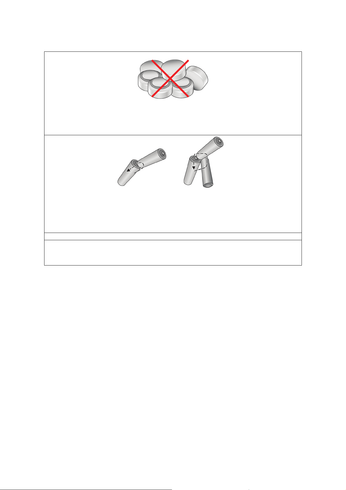
Safety Guidelines for Battery Usage
Button Batteries
(If applicable)
These are built-in on the motherboard.
Alkaline Manganese Batteries
(If applicable)
These are used in optional devices such as the wireless keyboard and wireless
mouse.
----Æ = Discharging Circuit
Storing batteries together can cause short circuits or discharging circuits when
terminals come into mutual contact. It will generate heat, leading to possible
combustion, explosion and personal injury and/or damage to property.
Use the following safety guidelines to help ensure your own personal safety and to
help protect your property and your environment from potential damage.
General Guidelines
• Batteries provide a safe and dependable source of power.
• Improper handling and installing of batteries or inconsistent use may lead to battery
leakage, heating or even explosion, leading to battery failure, fires and even risk of injury
or damage to property.
• It may pose several threats to personnel and property. Some hazards associate with
batteries include but not are limited to :
- Caustic and/or acid burns;
- Hydrogen gas accumulation and explosion;
- Electric shock;
- Potential high currents and explosions.
• Precautions must be noted and followed to prevent accidents. Make sure that you are using
the battery in an appropriate application as specified by the manufacturer.
Battery Use
• There is a danger of a new battery exploding if it is incorrectly installed.
• Any enclosure that houses batteries MUST be adequately ventilated. The amount of
ventilation required depends on the size and voltage of the batteries, temperature and the
amount of current used to charge them. Always follow the manufacturer’s
recommendations for handling and venting.
• Battery placement in any enclosure should ensure that there is minimal chance of
accidental shorting during routine maintenance and use. It is recommended that insulated
tools be used to reduce the risk of any short circuit or short to ground.
- 98 -

Do not install any spark-producing components in the same enclosures or in close
•
proximity to the batteries.
General Precautions
• Always insert batteries correctly, observing positive (+) and negative (-) polarity, marked
on the battery and the equipment.
• Do not short-circuit batteries. When the positive and negative terminals of a battery are in
direct contact with each other, the battery becomes short-circuited.
• Do not replace batteries with batteries which are not the same or equivalent to the type
recommended by the manufacturer.
• Do not charge non-rechargeable batteries.
• Do not heat batteries or expose them to heat. Do not dispose of batteries in fire.
• Do not spill food or liquids on your batteries.
• Avoid storing the batteries under high temperature, high humidity, direct sunlight or in
contact with water.
• Do not modify or tamper with batteries.
• Do not directly solder batteries.
• Do not disassemble batteries.
• Do not drop, crush, puncture or damage batteries in any way.
• Do not pile up or jumble up the batteries.
• In certain devices, battery terminals may come into contact with metallic parts of the
devices at the battery mounting point. Careful attention is necessary to avoid short-circuit
when a battery is mounted into the device.
• Keep batteries out of the reach of children. Do not allow children to replace batteries
without adult supervision.
• Do not mix batteries. When replacing batteries, replace all of them at the same time with
new batteries of the same brand and type.
• Remove exhausted batteries immediately from its equipment and dispose of them properly.
• Store unused batteries in their original sealed packaging until ready to use and keep them
away from metal objects or any combustible or explosive objects which may cause shortcircuit or any explosion.
• In case of eye contact with the battery electrolyte, immediately flush eyes thoroughly with
water, and consult a doctor. In case of electrolyte contact in mouth, immediately gargle
with water. Quickly seek medical advice and/or intervention in case of battery or
electrolyte ingestion. There needs to be eyewash and possibly a shower nearby in case of
accidental contact.
Additional Precautions for Alkaline Manganese Batteries (If applicable)
These are used in optional devices such as the wireless keyboard and wireless mouse.
• Take care not to touch the chemicals and electrolyte in batteries directly. If contact is
necessary, wear proper protection such as gloves, masks and goggles to protect your skin,
face and eyes. Since caustic alkaline solution is used in this battery system, there are
potential risks of damage to cloth, property and personal injury due to adhesion of the
solution. It may also cause loss of eyesight if the solution gets into the eyes.
• Avoid rough handling of battery cartons. Do not throw the cartons around, push or pull
them roughly, or subject them to excessive stress and pressure. Transport the cartons
gently and use sufficient padding where necessary.
• Do not pile up battery cartons in several layers or should not exceed a specified height.
Generally, this height should not exceed 1.5 m for cardboard packs.
- 99 -

Store batteries in well-ventilated, dry and cool conditions. Temperatures should be
•
between 10°C and 25°C, not exceeding 30°C. Please ensure that that no smoking or open
flames or ignition sources should be present where the batteries are stored.
• In distribution process such as transportation, display and storage, follow a “first in, first
out” policy to avoid storage for a long period.
Additional Precautions for Button Batteries (If applicable)
These are built-in on the motherboard.
CAUTION
Button batteries are considerably small and can easily be accidentally swallowed by
young children, so keep the batteries out of reach from young children and infants. If
swallowing or ingestion accidentally happens, consult a doctor immediately.
• Do not connect positive and negative terminals with a wire.
• Do not store or carry batteries with metal objects such as necklaces or hair pins. Contact
with the terminals could cause short-circuits and cause very high current flows through the
battery, generating heat. Consequently, the battery may be damaged, causing leakage or
explosion.
Disposal
• Do not dispose of the batteries along with household waste or in any ways not
recommended by the manufacturer.
• Dispose the battery in accordance with applicable federal, state and local regulations. For
example, in some countries, special bins are provided for you to discard used batteries.
- 100 -
 Loading...