


NEC NP500W, NP600G, NP500, NP400, NP400G User Manual 2
...
Portable Projector
NP600/NP500/NP400
NP500W
User’s Manual
The projector’s model name indicated on the projector’s label is
NP600, NP500, NP400, NP500W, NP600G, NP500G, NP400G, and
NP500WG respectively.
All the models are referred to as NP600, NP500, NP400, and NP500W
throughout the user’s manual except some of the specification
pages.

1st edition July 2008
• IBM is a trademark or registered trademark of International Business Machines Corporation.
• Macintosh, Mac OS X and PowerBook are trademarks of Apple Inc. registered in the U.S. and other countries.
• Microsoft, Windows, Windows Vista, and PowerPoint are either a registered trademark or trademark of Microsoft
Corporation in the United States and/or other countries.
• VESA is a registered trademark of Video Electronics Standards Association.
• MicroSaver is a registered trademark of Kensington Computer Products Group, a division of ACCO Brands.
• Other product and company names mentioned in this user’s manual may be the trademarks or registered trademarks
of their respective holders.
NOTES
(1) The contents of this user’s manual may not be reprinted in part or whole without permission.
(2) The contents of this user’s manual are subject to change without notice.
(3) Great care has been taken in the preparation of this user’s manual; however, should you notice any questionable
points, errors or omissions, please contact us.
(4) Notwithstanding article (3), NEC will not be responsible for any claims on loss of profit or other matters deemed
to result from using the Projector.
Important Information
Safety Cautions
Precautions
Please read this manual carefully before using your NEC NP600/NP500/NP400/NP500W projector and keep the
manual handy for future reference.
CAUTION
To turn off main power, be sure to remove the plug from power outlet.
The power outlet socket should be installed as near to the equipment as possible, and should be easily
accessible.
CAUTION
TO PREVENT SHOCK, DO NOT OPEN THE CABINET.
THERE ARE HIGH-VOLTAGE COMPONENTS INSIDE.
REFER SERVICING TO QUALIFIED SERVICE PERSONNEL.
This symbol warns the user that uninsulated voltage within the unit may be sufficient to cause electrical
shock. Therefore, it is dangerous to make any kind of contact with any part inside of the unit.
This symbol alerts the user that important information concerning the operation and maintenance of this
unit has been provided.
The information should be read carefully to avoid problems.
WARNING: TO PREVENT FIRE OR SHOCK, DO NOT EXPOSE THIS UNIT TO RAIN OR MOISTURE.
DO NOT USE THIS UNIT’S PLUG WITH AN EXTENSION CORD OR IN AN OUTLET UNLESS ALL THE PRONGS
CAN BE FULLY INSERTED.
DOC Compliance Notice (for Canada only)
This Class B digital apparatus meets all requirements of the Canadian Interference-Causing Equipment Regulations.
Machine Noise Information Regulation - 3. GPSGV,
The highest sound pressure level is less than 70 dB (A) in accordance with EN ISO 7779.
CAUTION
Avoid displaying stationary images for a prolonged period of time.
Doing so can result in these images being temporarily sustained on the surface of the LCD panel.
If this should happen, continue to use your projector. The static background from previous images will
disappear.
Disposing of your used product
EU-wide legislation as implemented in each Member State requires that used electrical and electronic
products carrying the mark (left) must be disposed of separately from normal household waste. This includes projectors and their electrical accessories or lamps. When you dispose of such products, please
follow the guidance of your local authority and/or ask the shop where you purchased the product.
After collecting the used products, they are reused and recycled in a proper way. This effort will help us
reduce the wastes as well as the negative impact such as mercury contained in a lamp to the human
health and the environment at the minimum level.
The mark on the electrical and electronic products only applies to the current European Union Member
States.
i

Important Information
WARNING TO CALIFORNIA RESIDENTS:
Handling the cables supplied with this product will expose you to lead, a chemical known to the State of California
to cause birth defects or other reproductive harm. WASH HANDS AFTER HANDLING.
RF Interference (for USA only)
WARNING
The Federal Communications Commission does not allow any modifications or changes to the unit EXCEPT those
specified by NEC Display Solutions of America, Inc. in this manual. Failure to comply with this government regulation could void your right to operate this equipment. This equipment has been tested and found to comply with
the limits for a Class B digital device, pursuant to Part 15 of the FCC Rules. These limits are designed to provide
reasonable protection against harmful interference in a residential installation. This equipment generates, uses, and
can radiate radio frequency energy and, if not installed and used in accordance with the instructions, may cause
harmful interference to radio communications. However, there is no guarantee that interference will not occur in a
particular installation.
If this equipment does cause harmful interference to radio or television reception, which can be determined by
turning the equipment off and on, the user is encouraged to try to correct the interference by one or more of the
following measures:
• Reorient or relocate the receiving antenna.
• Increase the separation between the equipment and receiver.
• Connect the equipment into an outlet on a circuit different from that to which the receiver is connected.
• Consult the dealer or an experienced radio / TV technician for help.
For UK only: In UK, a BS approved power cable with moulded plug has a Black (five Amps) fuse installed for use with
this equipment. If a power cable is not supplied with this equipment please contact your supplier.
Important Safeguards
These safety instructions are to ensure the long life of your projector and to prevent fire and shock. Please read them
carefully and heed all warnings.
Installation
• Do not place the projector in the following conditions:
- on an unstable cart, stand, or table.
- near water, baths, or damp rooms.
- in direct sunlight, near heaters, or heat radiating appliances.
- in a dusty, smoky or steamy environment.
- on a sheet of paper or cloth, rugs or carpets.
• If you wish to have the projector installed on the ceiling:
- Do not attempt to install the projector yourself.
- The projector must be installed by qualified technicians in order to ensure proper operation and reduce the risk
of bodily injury.
- In addition, the ceiling must be strong enough to support the projector and the installation must be in accordance
with any local building codes.
- Please consult your dealer for more information.
ii

Important Information
10˚
Place the projector in a horizontal position
The tilt angle of the projector should not exceed 10 degrees, nor should the projector be installed in any way other
than the desktop and ceiling mount, otherwise lamp life could decrease dramatically.
Fire and Shock Precautions
• Ensure that there is sufficient ventilation and that vents are unobstructed to prevent the build-up of heat inside your
projector. Allow at least 4 inches (10cm) of space between your projector and a wall.
• Do not try to touch the ventilation outlet on the left front (when seen from the front) as it can become heated while
the projector is turned on and immediately after the projector is turned off.
• Prevent foreign objects such as paper clips and bits of paper from falling into your projector. Do not attempt to retrieve
any objects that might fall into your projector. Do not insert any metal objects such as a wire or screwdriver into your
projector. If something should fall into your projector, disconnect it immediately and have the object removed by a
qualified service personnel.
• Do not place any objects on top of the projector.
• Do not touch the power plug during a thunderstorm. Doing so can cause electrical shock or fire.
• The projector is designed to operate on a power supply of 100-240V AC 50/60 Hz (NP600/NP500/NP400/NP500W)
or 200-240V AC 50/60 Hz (NP600G/NP500G/NP400G/NP500WG). Ensure that your power supply fits this requirement before attempting to use your projector.
• Do not look into the lens while the projector is on. Serious damage to your eyes could result.
• Keep any items such as magnifying glass out of the light path of the projector. The light being projected from the
lens is extensive, therefore any kind of abnormal objects that can redirect light coming out of the lens, can cause
unpredictable outcome such as fire or injury to the eyes.
• Do not cover the lens with the black lens cap or equivalent while the projector is on. Doing so can lead to melting
of the cap and possibly burning your hands due to the heat emitted from the light output.
• Do not place any objects, which are easily affected by heat, in front of the projector lens or a projector exhaust
vent.
Doing so could lead to the object melting or getting your hands burned from the heat that is emitted from the light
output and exhaust.
• Handle the power cable carefully. A damaged or frayed power cable can cause electric shock or fire.
- Do not use any power cables than the supplied one.
- Do not bend or tug the power cable excessively.
- Do not place the power cable under the projector, or any heavy object.
- Do not cover the power cable with other soft materials such as rugs.
- Do not heat the power cable.
- Do not handle the power plug with wet hands.
• Turn off the projector, unplug the power cable and have the projector serviced by a qualified service personnel under
the following conditions:
- When the power cable or plug is damaged or frayed.
- If liquid has been spilled into the projector, or if it has been exposed to rain or water.
- If the projector does not operate normally when you follow the instructions described in this user’s manual.
- If the projector has been dropped or the cabinet has been damaged.
- If the projector exhibits a distinct change in performance, indicating a need for service.
• Disconnect the power cable and any other cables before carrying the projector.
• Turn off the projector and unplug the power cable before cleaning the cabinet or replacing the lamp.
• Turn off the projector and unplug the power cable if the projector is not to be used for an extended period of time.
• When using a LAN cable:
For safety, do not connect to the connector for peripheral device wiring that might have excessive voltage.
iii
Important Information
CAUTION
• Do not use the tilt-foot for purposes other than originally intended. Misuses such as gripping the tilt-foot or hanging on the wall can cause damage to the projector.
• Do not send the projector in the soft case by parcel delivery service or cargo shipment. The projector inside the
soft case could be damaged.
• Select [HIGH] in Fan mode if you continue to use the projector for consecutive days. (From the menu, select
[SETUP] - [OPTIONS(1)] → [FAN MODE] → [HIGH].)
• Do not try to touch the ventilation outlet on the left front (when seen from the front) as it can become heated while
the projector is turned on and immediately after the projector is turned off.
• Do not turn off the AC power for 60 seconds after the lamp is turned on and while the POWER indicator is blink
ing green. Doing so could cause premature lamp failure.
Remote Control Precautions
• Handle the remote control carefully.
• If the remote control gets wet, wipe it dry immediately.
• Avoid excessive heat and humidity.
• Do not heat, take apart, or throw batteries into fire.
• If you will not be using the remote control for a long time, remove the batteries.
• Ensure that you have the batteries’ polarity (+/-) aligned correctly.
• Do not use new and old batteries together, or use different types of batteries together.
• Dispose of used batteries according to your local regulations.
-
Lamp Replacement
• To replace the lamp, follow all instructions provided on page 72.
• Be sure to replace the lamp when the message
PLEASE REPLACE THE LAMP.] appears. If you continue to use the lamp after the lamp has reached the end
of its usable life, the lamp bulb may shatter, and pieces of glass may be scattered in the lamp case. Do not touch
them as the pieces of glass may cause injury.
If this happens, contact your dealer for lamp replacement.
[THE LAMP HAS REACHED THE END OF ITS USABLE LIFE.
A Lamp Characteristic
The projector has a high-pressure mercury lamp as a light source.
A lamp has a characteristic that its brightness gradually decreases with age. Also repeatedly turning the lamp on
and off will increase the possibility of its lower brightness.
CAUTION:
When removing the lamp from a ceiling-mounted projector, make sure that no one is under the projector. Glass
fragments could fall if the lamp has been burned out.
iv

Important Information
About High Altitude mode
•
Set [FAN MODE] to [HIGH ALTITUDE] when using the projector at altitudes approximately 5500 feet/1600 meters or
higher.
Using the projector at altitudes approximately 5500 feet/1600 meters or higher without setting to [HIGH ALTITUDE]
can cause the projector to overheat and the protector could shut down. If this happens, wait a couple minutes and
turn on the projector.
• Using the projector at altitudes less than approximately 5500 feet/1600 meters and setting to [HIGH ALTITUDE]
can cause the lamp to overcool, causing the image to flicker. Switch [FAN MODE] to [AUTO].
• Using the projector at altitudes approximately 5500 feet/1600 meters or higher can shorten the life of optical com
ponents such as the lamp.
About Copyright of original projected pictures:
Please note that using this projector for the purpose of commercial gain or the attraction of public attention in a venue
such as a coffee shop or hotel and employing compression or expansion of the screen image with the following functions may raise concern about the infringement of copyrights which are protected by copyright law.
[ASPECT RATIO], [KEYSTONE], Magnifying feature and other similar features.
-
v

Table of Contents
Important Information ............................................................................................i
1. Introduction .......................................................................................................... 1
1 What’s in the Box? ......................................................................................................... 1
Introduction to the Projector .......................................................................................... 2
Congratulations on Your Purchase of the Projector ................................................. 2
Features you’ll enjoy: ............................................................................................... 2
About this user’s manual .......................................................................................... 3
Part Names of the Projector .......................................................................................... 4
Front/Top .................................................................................................................. 4
Rear ......................................................................................................................... 4
Top Features ............................................................................................................ 5
Terminal Panel Features .......................................................................................... 6
Part Names of the Remote Control ............................................................................... 7
Battery Installation ................................................................................................... 8
Remote Control Precautions .................................................................................... 8
Operating Range for Wireless Remote Control ........................................................ 8
2. Installation and Connections ..................................................................... 9
1 Setting Up the Screen and the Projector ....................................................................... 9
Selecting a Location................................................................................................. 9
Throw Distance and Screen Size ........................................................................... 11
Making Connections .................................................................................................... 13
Enabling the computer’s external display ............................................................... 13
Connecting Your PC or Macintosh Computer ......................................................... 13
When Viewing a DVI Digital Signal ........................................................................ 15
Using Two Analog COMPUTER Inputs Simultaneously ......................................... 16
Connecting an External Monitor ............................................................................ 17
Connecting Your DVD Player with Component Output ........................................... 18
Connecting Your VCR............................................................................................. 19
Connecting the Supplied Power Cable .................................................................. 21
3. Projecting an Image (Basic Operation) .............................................. 22
1 Turning on the Projector .............................................................................................. 22
Note on Startup screen (Menu Language Select screen) ...................................... 23
Selecting a Source ...................................................................................................... 24
Selecting the computer or video source................................................................. 24
Adjusting the Picture Size and Position ....................................................................... 25
Adjust the Tilt Foot ................................................................................................. 26
Zoom ...................................................................................................................... 27
Focus ..................................................................................................................... 27
Correcting Keystone Distortion .................................................................................... 28
Correcting Keystone Distortion .............................................................................. 28
Adjusting with buttons on the cabinet .................................................................... 28
Adjusting with the Remote Control......................................................................... 29
Adjusting with the Auto Keystone Function ............................................................ 30
Optimizing Computer Signal Automatically ................................................................. 31
Adjusting the Image Using Auto Adjust .................................................................. 31
Turning Up or Down Volume ........................................................................................ 31
vi

Table of Contents
7 Turning off the Projector .............................................................................................. 32
After Use...................................................................................................................... 33
4. Convenient Features ..................................................................................... 34
1 Turning off the Image and Sound ................................................................................ 34
Freezing a Picture ....................................................................................................... 34
Enlarging a Picture ...................................................................................................... 34
Changing Lamp Mode ................................................................................................. 35
Preventing the Unauthorized Use of the Projector [SECURITY] ................................. 36
Using the Optional Remote Mouse Receiver (NP01MR) ............................................ 39
7 Network Setting by Using an HTTP Browser ............................................................... 41
Using the VGA Signal Cable to Operate the Projector (Virtual Remote) ..................... 44
5. Using On-Screen Menu ................................................................................ 45
1 Using the Menus .......................................................................................................... 45
Menu Elements ............................................................................................................ 46
List of Menu Items ....................................................................................................... 47
Menu Descriptions & Functions [SOURCE] ................................................................ 49
Menu Descriptions & Functions [ADJUST] .................................................................. 50
Menu Descriptions & Functions [SETUP] .................................................................... 57
7 Menu Descriptions & Functions [INFO.] ...................................................................... 67
Menu Descriptions & Functions [RESET] .................................................................... 69
6. Maintenance ...................................................................................................... 70
1 Cleaning or Replacing the Filters ................................................................................ 70
Cleaning the Cabinet and the Lens ............................................................................. 71
Replacing the Lamp..................................................................................................... 72
7. Appendix ............................................................................................................... 75
1 Troubleshooting ........................................................................................................... 75
Indicator Messages ................................................................................................ 75
Specifications .............................................................................................................. 78
Cabinet Dimensions .................................................................................................... 80
Pin Assignments of D-Sub COMPUTER Input Connector .......................................... 81
Mini D-Sub 15 Pin Connector ................................................................................ 81
Compatible Input Signal List ........................................................................................ 82
PC Control Codes and Cable Connection ................................................................... 83
PC Control Codes .................................................................................................. 83
Cable Connection .................................................................................................. 83
PC Control Connector (D-SUB 9P) ........................................................................ 83
7 Troubleshooting Check List .......................................................................................... 84
TravelCare Guide ......................................................................................................... 86
vii
S
T
AT
US
LA
M
P
A
U
T
O
A
D
J.
S
O
U
R
C
E
S
E
L
E
C
T
M
E
N
U
E
X
I
T
E
N
T
E
R
F
O
C
U
S
1. Introduction
V
O
L
U
M
E
S
V
I
D
E
O
V
I
D
E
O
L
C
L
I
C
K
E
N
T
E
R
E
X
I
T
M
E
N
U
U
P
M
A
G
N
I
F
Y
P
A
G
E
O
F
F
P
O
W
E
R
O
N
P
I
C
M
U
T
E
D
O
W
N
M
O
U
S
E
R
C
L
I
C
K
A
U
T
O
A
D
J
.
L
A
M
P
M
O
D
E
C
O
M
P
U
T
E
R
A
S
P
E
C
T
H
E
L
P
F
R
E
E
Z
E
P
I
C
T
U
R
E
1
2
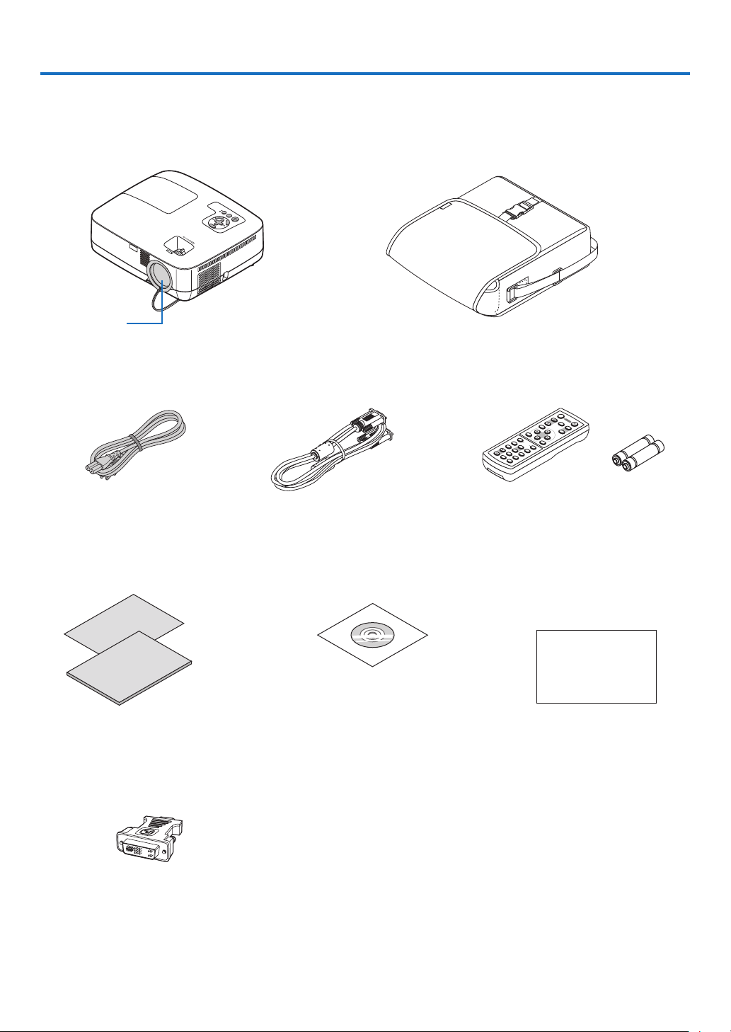
1 What’s in the Box?
Make sure your box contains everything listed. If any pieces are missing, contact your dealer.
Please save the original box and packing materials if you ever need to ship your projector.
Projector
Lens cap
(24F44681)
Soft case
(24BS7582)
Power cable
(US: 7N080229)
(EU: 7N080015)
DVI to VGA adapter (7N960233)
Quick Setup Guide
(7N8P8811)
Important Information
(7N8P8821)
VGA signal cable
(7N520052)
CD-ROM
User’s manual
(7N951211)
1
Remote control
(7N900731)
For North America only
Registration card
Limited warranty
For Europe only
Guarantee policy
Batteries (AAA2)

1. Introduction
Introduction to the Projector
This section introduces you to your new projector and describes the features and controls.
Congratulations on Your Purchase of the Projector
This projector is one of the very best projectors available today. The projector enables you to project precise images
up to 300 inches across (measured diagonally) from your PC or Macintosh computer (desktop or notebook), VCR,
DVD player, or document camera.
You can use the projector on a tabletop or cart, you can use the projector to project images from behind the screen,
and the projector can be permanently mounted on a ceiling*1. The remote control can be used wirelessly.
*1 Do not attempt to mount the projector on a ceiling yourself.
The projector must be installed by qualified technicians in order to ensure proper operation and reduce the risk
of bodily injury.
In addition, the ceiling must be strong enough to support the projector and the installation must be in accordance
with any local building codes. Please consult your dealer for more information.
Features you’ll enjoy:
• Quick start & Direct Power Off
Eight seconds after turning on the power, the projector is ready to display PC or video images.
The projector has a feature called “Direct Power Off”. This feature allows the projector to be turned off (even when
projecting an image) using a power strip equipped with a switch and a breaker.
• AUTO POWER ON and AUTO POWER OFF features
The AUTO POWER ON(AC), AUTO POWER ON(COMP1), AUTO POWER OFF, and OFF TIMER features eliminate
the need to always use the POWER button on the remote control or projector cabinet.
• Virtual Remote function
The Virtual Remote function allows power On/Off and source selection of the projector from your PC by using the
supplied VGA signal cable. The utility software “Virtual Remote Tool” exclusively for the projector is required to be
downloaded from our website.
• The optional remote control (NP02RC) allows you to assign a CONTROL ID to the projector
Multiple projectors can be operated separately and independently with the same single remote control by assigning
an ID number to each projector.
• A variety of input ports and a comprehensive array of system control interfaces
This projector supports input signals on the following ports: DVI-I connector (DVI-I 29 Pin) with HDCP compatible,
15pin D-Sub, composite and S-video.
• Integrated RJ-45 connector for wired networking capability
An RJ-45 connector is equipped as standard feature.
• 7W built-in speaker for an integrated audio solution
Powerful 7 watt speaker provides volume need for large rooms.
• Auto vertical keystone correction
Auto Keystone feature allows the projector to detect its tilt and correct vertical distortion automatically.
• LCD projector with high resolution and high brightness
High resolution display - up to UXGA compatible, XGA (NP600/NP500/NP400)/WXGA (NP500W) native resolu-
tion.
• Six picture preset modes for user adjustable picture and color settings
Each picture preset mode can be customized and memorized according to your preference.
2

1. Introduction
• Preventing unauthorized use of the projector
Enhanced smart security settings for keyword protection, cabinet control panel lock, security slot, and security
chain opening to help prevent unauthorized access, adjustments and theft deterrence.
• PC Control Port
You can control the projector with a PC or control system using the PC Control port.
• 3W in standby condition with energy saving technology
Selecting [POWER-SAVING] for [STANDBY MODE] from the menu can put the projector in power-saving mode
that consume less power than the normal standby condition.
• Optional remote mouse receiver
You can use the supplied wireless remote control and the optional remote mouse receiver to operate your PC
mouse from across the room. The optional remote mouse receiver (NP01MR) supports almost any PC using a
USB connection.
About this user’s manual
The fastest way to get started is to take your time and do everything right the first time. Take a few minutes now to
review the user’s manual. This may save you time later on. At the beginning of each section of the manual you’ll find
an overview. If the section doesn’t apply, you can skip it.
3
S
T
A
T
U
S
L
AM
P
AU
T
O
A
D
J
.
SO
U
R
CE
S
E
L
E
C
T
M
E
N
U
E
X
I
T
E
N
T
E
R
FOCU
S
Part Names of the Projector
S
E
L
E
C
T
M
E
N
U
E
X
I
T
ENTE
R
S
T
A
TU
S
L
A
M
P
A
UT
O
A
D
J
.
S
O
U
R
C
E
F
O
C
U
S
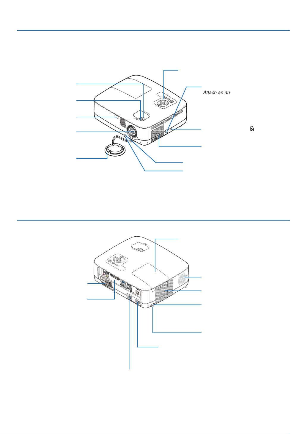
Front/Top
Zoom Lever
* This security slot supports the MicroSaver ® Security System.
(→ page 27)
Focus Ring
(→ page 27)
Remote sensor
(→ page 8)
Lens
Lens Cap
1. Introduction
Controls
(→ page 5)
Security chain opening
Attach an anti-theft device.
The security chain opening accepts security wires or chains up to 0.18 inch/
4.6 mm in diameter.
Built-in Security Slot ( )*
Ventilation (inlet) / Filter Cover
(→ page 70)
Adjustable Tilt Foot Lever (→ page 26)
Adjustable Tilt Foot (→ page 26)
Rear
Ventilation (inlet) / Filter Cover
Terminal Panel (→ page 6)
(→ page 70)
Lamp Cover (→ page 72)
Monaural Speaker (7W)
Ventilation (outlet)
Heated air is exhausted from here.
Spacer (black rubber)
To fine-adjust the height of the rear foot,
remove the spacer and rotate the rear
foot to the desired height.
Rear Foot (→ page 26)
AC Input
Connect the supplied power cable’s two-pin plug here, and
plug the other end into an active wall outlet. (→ page 21)
Main Power Switch
When you plug the supplied power cable into an active wall outlet
and turn on the Main Power, the POWER indicator turns orange
and the projector is in standby mode.
(→ page 22,32)
4

Top Features
SELECT
MENU
EX
I
T
ENTER
STATUS
LAMP
AUTO ADJ. SOURCE
1 2 5 6
4
7
8
109
3
1. (POWER) Button (→page 22, 32)
2. POWER Indicator (→page 22, 32, 75)
3. STATUS Indicator (→page 75)
4. LAMP Indicator (→page 72, 75)
5. SOURCE Button (→page 24)
6. AUTO ADJ. Button (→page 31)
7. MENU Button (→page 45)
8. SELECT / Volume Buttons / Keystone
Buttons (→page 28, 31)
9. ENTER Button
10. EXIT Button
1. Introduction
5
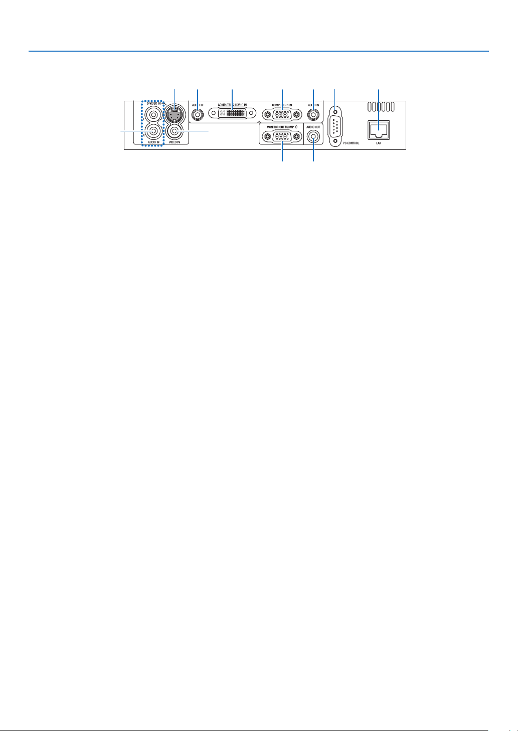
Terminal Panel Features
6
8 7
3 3 2 1
5 4
9 10
1. COMPUTER 1 IN/ Component Input Connector
(Mini D-Sub 15 Pin)
2. COMPUTER 2 (DVI-I) IN Connector (29 Pin) (HDCP
compatible)
3. AUDIO IN Mini Jack (Stereo Mini)
(→page 13,15,18)
4. AUDIO OUT Mini Jack (Stereo Mini) (→page 17)
5. MONITOR OUT (COMP 1) Connector (Mini D-Sub
15 Pin)
6. S-VIDEO IN Connector (Mini DIN 4 Pin)
(
7. VIDEO IN Connector (RCA)
8. AUDIO Input Jacks L/R (RCA) (→page 19)
9. PC CONTROL [PC CONTROL] Port (D-Sub 9 Pin)
(→page 83)
Use this port to connect a PC or control system.
This enables you to control the projector using serial
communication protocol. If you are writing your own
program, typical PC control codes are on page 83.
10. LAN Port (RJ-45) (→page 20)
(→page 17)
→page 19)
(→page 13,16,18)
(→page 15,16)
(→page 19)
1. Introduction
6
Part Names of the Remote Control
VOLUME
L-CLICK
ENTER
EXIT
MENU
UP
MAGNIFY PAGE
OFF
POWER
ON
PIC-MUTE
DOWN
MOUSE
R-CLICK
COMPUTER
ASPECT HELP
FREEZEPICTURE
S-VIDEO
VIDEO
COMPUTER
AUTO ADJ.
LAMP MODE
2
1
1
3
4
7
6
9
2
8
10
11
13
14
12
21
22
20
16
15
18
5
17
19
1. Introduction
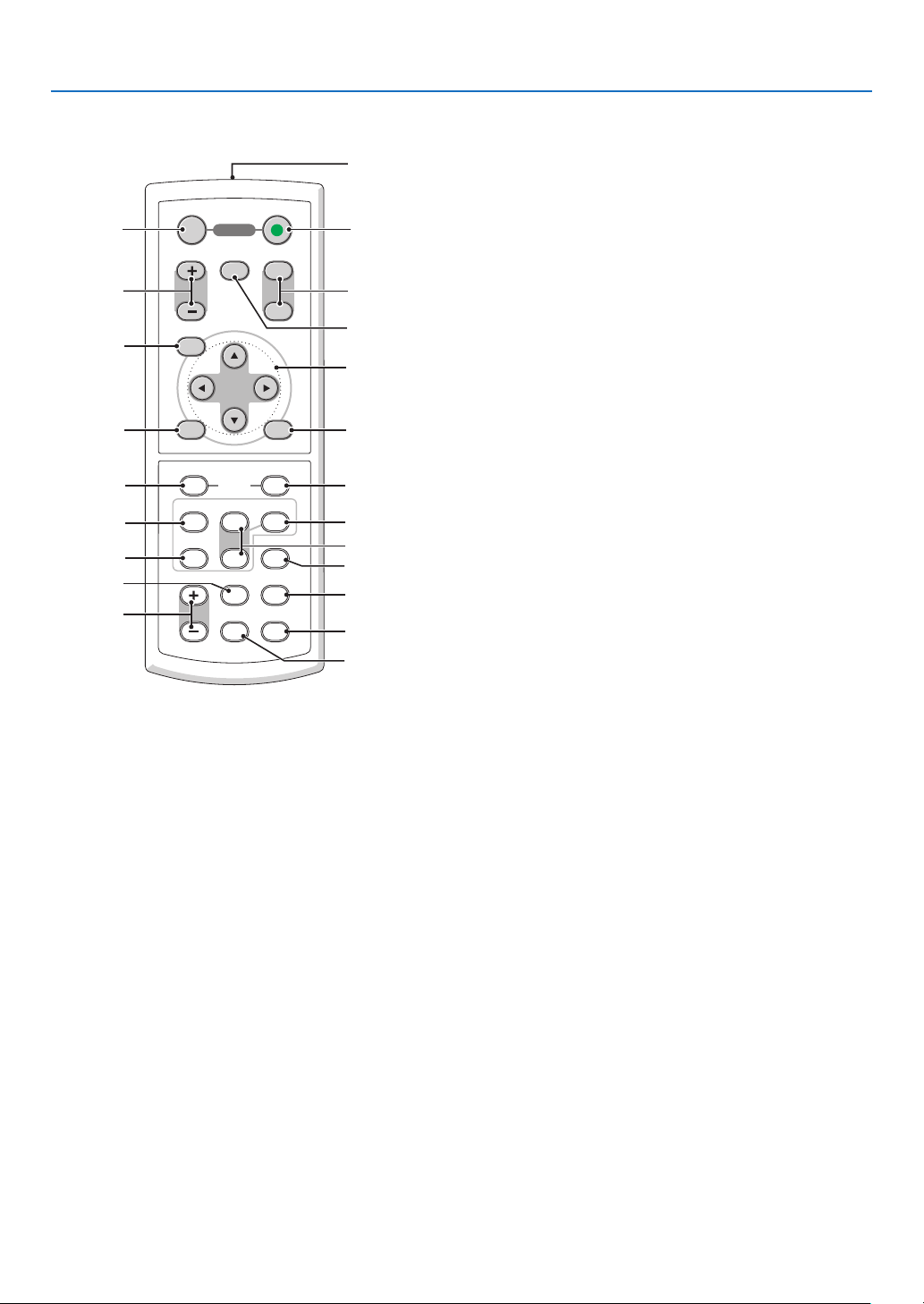
12. MOUSE R-CLICK Button*
(
1. Infrared Transmitter
(
→ page 8)
2. POWER ON Button
(
→ page 22)
3. POWER OFF Button
(
→ page 32)
4. MAGNIFY (+)(–) Button
(
5. PIC-MUTE Button
(
6. PAGE UP/DOWN Button*
(
7. MENU Button
(
8. SELECT Button (→ page 45)
9. ENTER Button (→ page 45)
10. EXIT Button (→ page 45)
11. MOUSE L-CLICK Button*
(
→ page 34)
→ page 34)
→ page 39,40)
→ page 45)
→ page 39,40)
* The PAGE UP/DOWN, MOUSE L-CLICK and MOUSE R-CLICK buttons work only when the optional remote mouse
receiver is connected with your computer.
→ page 39,40)
13. VIDEO Button
(
→ page 24)
14. S-VIDEO Button
(
→ page 24)
15. COMPUTER 1/2 Button
(
→ page 24)
16. AUTO ADJ. Button
(
→ page 31)
17. VOLUME (+)(–) Button
(
→ page 31)
18. LAMP MODE Button (→ page 35)
19. ASPECT Button
(
→ page 54)
20. PICTURE Button
(
→ page 50,51)
21. HELP Button
(
→ page 67)
22. FREEZE Button
(
→ page 34)
7
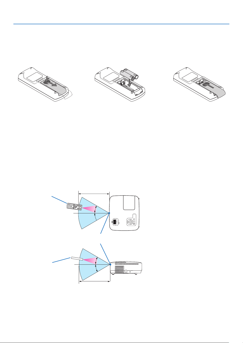
Battery Installation
SELECT
MENU
E
X
I
T
E
N
T
E
R
STATUS
LAMP
AUTO ADJ. SOURCE
FOCUS
30°
30°
30°
30°
1. Introduction
1
Press firmly and slide the
battery cover off.
2
Install new batteries (AAA). Ensure that you have the batteries’
polarity (+/–) aligned correctly.
3
Slip the cover back over the batteries until it snaps into place. Do
not mix different types of batteries
or new and old batteries.
Remote Control Precautions
• Handle the remote control carefully.
• If the remote control gets wet, wipe it dry immediately.
• Avoid excessive heat and humidity.
• Do not heat, take apart, or throw batteries into fire.
• If you will not be using the remote control for a long time, remove the batteries.
• Ensure that you have the batteries’ polarity (+/-) aligned correctly.
• Do not use new and old batteries together, or use different types of batteries together.
• Dispose of used batteries according to your local regulations.
Operating Range for Wireless Remote Control
Remote control
7m/22feet
Remote sensor on projector cabinet
Remote control
7m/22feet
• The infrared signal operates by line-of-sight up to a distance of about 22 feet/7 m and within a 60-degree angle of
the remote sensor on the projector cabinet.
• The projector will not respond if there are objects between the remote control and the sensor, or if strong light falls
on the sensor. Weak batteries will also prevent the remote control from properly operating the projector.
8
2. Installation and Connections
S
E
L
E
C
T
M
E
N
U
E
X
I
T
E
N
T
E
R
S
T
A
T
U
S
L
A
M
P
A
U
T
O
A
D
J
.
S
O
U
RC
E
F
O
C
U
S
300"
240"
Dis
tance
(U
nit:
m
/i
nc
h
)
Lens center
Screen Size
Screen Size (Unit: cm/inch)
200"
180"
150"
120"
100"
80"
10.3/407
"
8.3/325
"
6.2/244
"
5.1/203
"
4.1/162
"
3.4/135
"
2.7/107
"
2.0/81
"
1.3/53
"
40"
6.9/271
"
60"
S
E
L
E
C
T
M
E
N
U
E
X
I
T
E
N
T
E
R
S
T
A
T
U
S
L
A
M
P
A
U
T
O
A
D
J
.
S
O
U
R
C
E
F
O
C
U
S
30"
21"
1.0/
40
"
0.8/
30
"
609.6(W)�457.2(H) / 240(W)�180(H)
487.7(W)�365.8(H) / 192(W)�144(H)
406.4(W)�304.8(H) / 160(W)�120(H)
304.8(W)�228.6(H) / 120(W)�90(H)
365.8(W)�274.3(H) / 144(W)�108(H)
243.8(W)�182.9(H) / 96(W)�72(H)
203.2(W)�152.4(H) / 80(W)�60(H)
162.6(W)�121.9(H) / 64(W)�48(H)
121.9(W)�91.4(H) / 48(W)�36(H)
81.3(W)�61.0(H) / 32(W)�24(H)
61.0(W)�45.7(H) / 24(W)�18(H)
42.7(W)�32(H) / 17(W)�13(H)
This section describes how to set up your projector and how to connect video and audio sources.
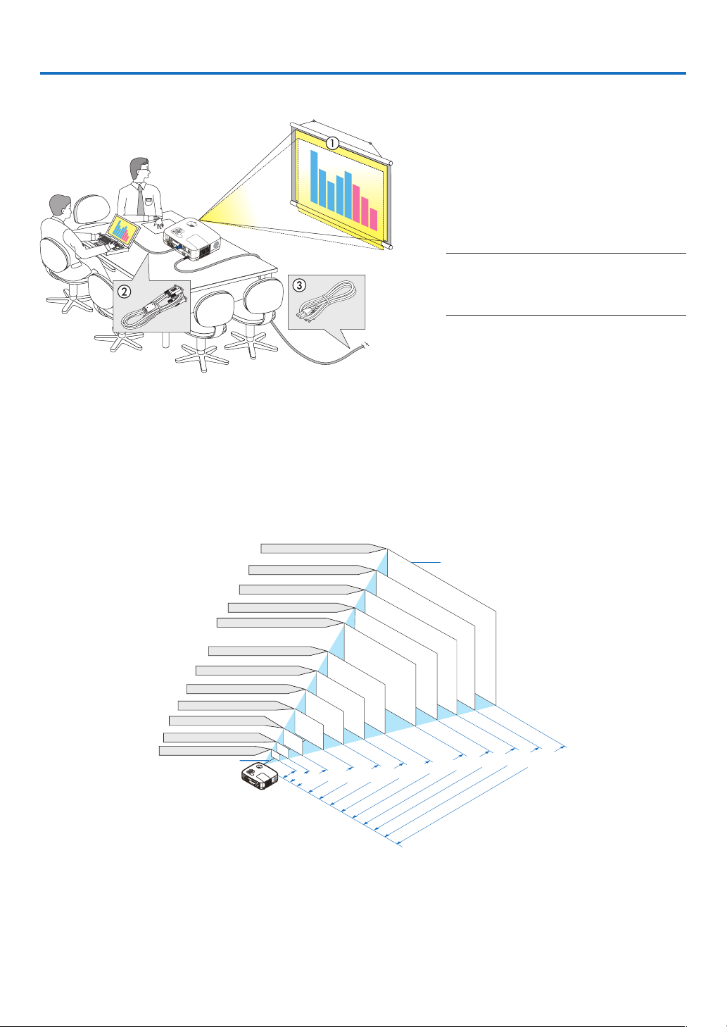
Your projector is simple to set up and use. But before you get started, you must first:
z Set up a screen and the projector.
x Connect your computer or video equip-
ment to the projector.
(→ page 13,15,16,17,18,19,20)
c Connect the supplied power cable.
(→ page 21)
NOTE: Ensure that the power cable and any other
cables are disconnected before moving the projector. When moving the projector or when it is not
in use, cover the lens with the lens cap.
To the wall outlet.
1 Setting Up the Screen and the Projector
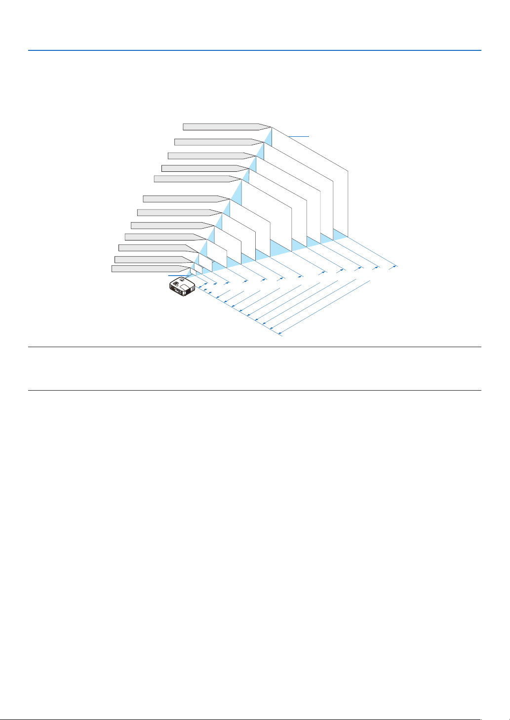
Selecting a Location
[NP600/NP500/NP400]
The further your projector is from the screen or wall, the larger the image. The minimum size the image can be is
approximately 21" (0.53 m) measured diagonally when the projector is roughly 30 inches (0.8 m) from the wall or
screen. The largest the image can be is 300" (7.6 m) when the projector is about 407 inches (10.3 m) from the wall
or screen.
9
2. Installation and Connections
300"
240"
D
ista
n
ce
(U
nit:
m
/i
nc
h
)
Lens center
Screen Size
Screen Size (Unit: cm/inch)
200"
180"
150"
120"
100"
80"
9.7/384
"
7.8/307
"
5.8/230
"
4.9/191
"
3.9/153
"
3.2/127
"
2.6/102
"
1.9/76
"
1.3/50
"
40"
6.5/255
"
60"
S
E
L
E
C
T
M
E
N
U
E
X
I
T
E
N
T
E
R
S
T
A
T
U
S
L
A
M
P
A
U
T
O
A
D
J
.
S
O
U
R
C
E
F
O
C
U
S
30"
21"
0.94/
38
"
0.7/
28
"
646.2(W)�403.9(H) / 254(W)�159(H)
516.9(W)�323.1(H) / 204(W)�127(H)
430.8(W)�269.2(H) / 170(W)�106(H)
323.1(W)�201.9(H) / 127(W)�79(H)
387.7(W)�242.3(H) / 153(W)�95(H)
258.5(W)�161.5(H) / 102(W)�64(H)
215.4(W)�134.6(H) / 85(W)�53(H)
172.3(W)�107.7(H) / 68(W)�42(H)
129.2(W)�80.8(H) / 51(W)�32(H)
86.2(W)�53.8(H) / 34(W)�21(H)
64.6(W)�40.4(H) / 25(W)�16(H)
45.2(W)�28.3(H) / 18(W)�11(H)
[NP500W]
The further your projector is from the screen or wall, the larger the image. The minimum size the image can be is
approximately 21" (0.53 m) measured diagonally when the projector is roughly 28 inches (0.7 m) from the wall or
screen. The largest the image can be is 300" (7.6 m) when the projector is about 384 inches (9.7 m) from the wall or
screen.
TIP:
• The distances are indicated by intermediate values between tele and wide. Use as a rule of thumb.
• The Zoom lever adjusts the image size +/-10%
• For more details on throw distance, see page
11.
10
2. Installation and Connections
C
α
B
D
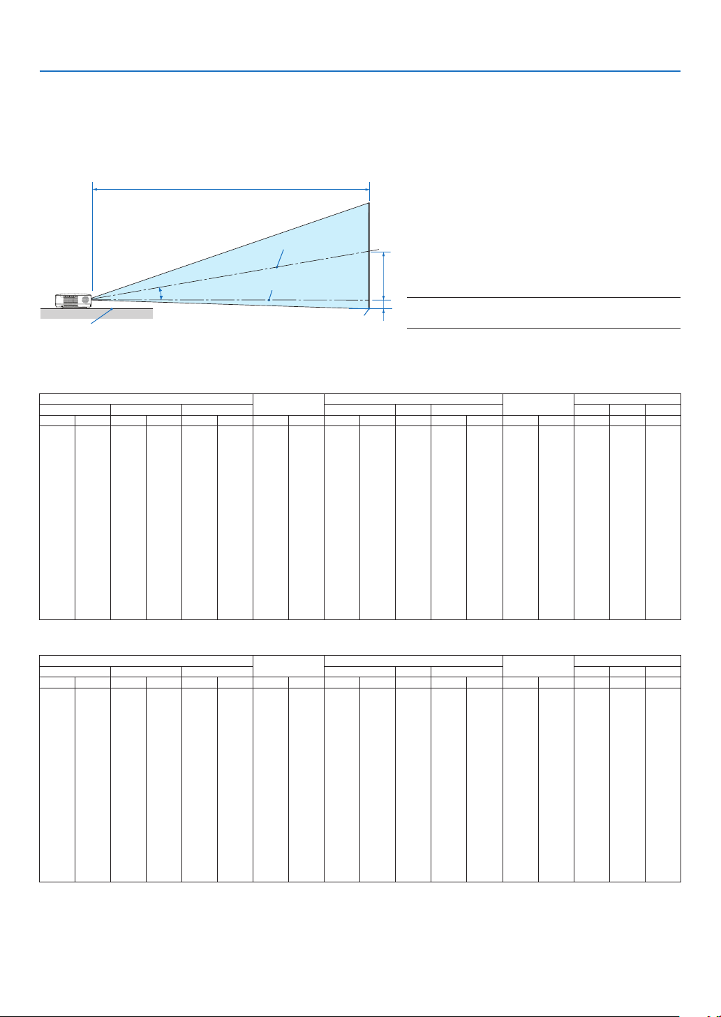
Throw Distance and Screen Size
The following shows the proper relative positions of the projector and screen. Refer to the table to determine the
position of installation.
Distance Chart
B = Vertical distance between lens center and
screen center
C = Throw distance
Screen center
Lens center
Projector bottom
Screen bottom
[NP600/NP500/NP400]
Diagonal Width Height wide tele wide tele
inch mm inch mm inch mm inch mm inch mm - inch mm inch mm degree - degree
21 533 17 427 13 320 4 110 - - - 30 753 -2 -50 - - 8.3
25 635 20 508 15 381 5 131 29 746 - 36 903 -2 -60 10.0 - 8.3
30 762 24 610 18 457 6 157 36 903 - 43 1092 -3 -71 9.9 - 8.2
40 1016 32 813 24 610 8 210 48 1217 - 58 1469 -4 -95 9.8 - 8.1
60 1524 48 1219 36 914 12 314 73 1845 - 88 2223 -6 -143 9.7 - 8.0
72 1829 58 1463 43 1097 15 377 87 2221 - 105 2675 -7 -171 9.6 - 8.0
80 2032 64 1626 48 1219 17 419 97 2473 - 117 2977 -8 -191 9.6 - 8.0
84 2134 67 1707 50 1280 17 440 102 2598 - 123 3128 -8 -200 9.6 - 8.0
90 2286 72 1829 54 1372 19 471 110 2787 - 132 3354 -8 -214 9.6 - 8.0
100 2540 80 2032 60 1524 21 524 122 3101 - 147 3731 -9 -238 9.6 - 8.0
120 3048 96 2438 72 1829 25 629 147 3729 - 177 4485 -11 -286 9.6 - 8.0
150 3810 120 3048 90 2286 31 786 184 4671 - 221 5616 -14 -357 9.5 - 8.0
180 4572 144 3658 108 2743 37 943 221 5613 - 266 6747 -17 -429 9.5 - 8.0
200 5080 160 4064 120 3048 41 1048 246 6241 - 295 7501 -19 -476 9.5 - 8.0
210 5334 168 4267 126 3200 43 1100 258 6555 - 310 7878 -20 -500 9.5 - 7.9
240 6096 192 4877 144 3658 50 1257 295 7497 - 355 9009 -23 -572 9.5 - 7.9
270 6858 216 5486 162 4115 56 1414 332 8439 - 399 10140 -25 -643 9.5 - 7.9
300 7620 240 6096 180 4572 62 1572 369 9381 - 444 11271 -28 -714 9.5 - 7.9
Screen Size
B
D = Vertical distance between lens center and
screen bottom (top of screen for ceiling application)
α = Throw angle
NOTE: The values in the tables are design values and
may vary.
C
D
α
[NP500W]
Diagonal Width Height wide tele wide tele
inch mm inch mm inch mm inch mm inch mm - inch mm inch mm degree - degree
21 533 18 452 11 283 4 99 - - - 28 712 -2 -42 - - 7.9
25 635 21 538 13 337 5 118 28 703 - 34 854 -2 -50 9.5 - 7.9
30 762 25 646 16 404 6 141 34 851 - 41 1032 -2 -61 9.4 - 7.8
40 1016 34 862 21 538 7 188 45 1146 - 55 1389 -3 -81 9.3 - 7.7
60 1524 51 1292 32 808 11 283 68 1737 - 83 2101 -5 -121 9.2 - 7.7
72 1829 61 1551 38 969 13 339 82 2092 - 100 2528 -6 -145 9.2 - 7.6
80 2032 68 1723 42 1077 15 377 92 2328 - 111 2813 -6 -162 9.2 - 7.6
84 2134 71 1809 45 1131 16 396 96 2446 - 116 2955 -7 -170 9.2 - 7.6
90 2286 76 1939 48 1212 17 424 103 2624 - 125 3169 -7 -182 9.2 - 7.6
100 2540 85 2154 53 1346 19 471 115 2919 - 139 3525 -8 -202 9.2 - 7.6
120 3048 102 2585 64 1615 22 565 138 3510 - 167 4237 -10 -242 9.2 - 7.6
150 3810 127 3231 79 2019 28 707 173 4396 - 209 5305 -12 -303 9.1 - 7.6
180 4572 153 3877 95 2423 33 848 208 5283 - 251 6374 -14 -363 9.1 - 7.6
200 5080 170 4308 106 2692 37 942 231 5874 - 279 7086 -16 -404 9.1 - 7.6
210 5334 178 4523 111 2827 39 989 243 6169 - 293 7442 -17 -424 9.1 - 7.6
240 6096 204 5169 127 3231 45 1131 278 7056 - 335 8510 -19 -485 9.1 - 7.6
270 6858 229 5816 143 3635 50 1272 313 7942 - 377 9578 -21 -545 9.1 - 7.6
300 7620 254 6462 159 4039 56 1414 348 8829 - 419 10646 -24 -606 9.1 - 7.6
Screen Size
B
C
D
11
α

2. Installation and Connections
WARNING
* Installing your projector on the ceiling must be done
by a qualified technician. Contact your NEC dealer for
more information.
* Do not attempt to install the projector yourself.
• Only use your projector on a solid, level surface. If the
projector falls to the ground, you can be injured and
the projector severely damaged.
• Do not use the projector where temperatures vary
greatly. The projector must be used at temperatures
between 41˚F (5˚C) and 104˚F (40˚C) (Eco mode selected automatically at 95˚F to 104˚F/35˚C to 40˚C).
• Do not expose the projector to moisture, dust, or
smoke. This will harm the screen image.
• Ensure that you have adequate ventilation around your
projector so heat can dissipate. Do not cover the vents
on the side or the front of the projector.
Reflecting the Image
Using a mirror to reflect your projector’s image enables
you to enjoy a much larger image when a smaller space
is required. Contact your NEC dealer if you need a mirror
system. If you’re using a mirror system and your image
is inverted, use the MENU and SELECT buttons on your
projector cabinet or your remote control to correct the
orientation. (→ page 60)
12
2. Installation and Connections
COMPUTER 1 IN
AUDIO IN
PHONE
Making Connections
NOTE: When using with a notebook PC, be sure to connect the projector and notebook PC while the projector is in standby mode
and before turning on the power to the notebook PC.
In most cases the output signal from the notebook PC is not turned on unless connected to the projector before being powered up.
* If the screen goes blank while using your remote control, it may be the result of the computer’s screen-saver or power manage
ment software.
Enabling the computer’s external display
Displaying an image on the notebook PC’s screen does not necessarily mean it outputs a signal to the projector.
When using a PC compatible laptop, a combination of function keys will enable/disable the external display.
Usually, the combination of the ‘Fn” key along with one of the 12 function keys gets the external display to come on
or off. For example, NEC laptops use Fn + F3, while Dell laptops use Fn + F8 key combinations to toggle through
external display selections.
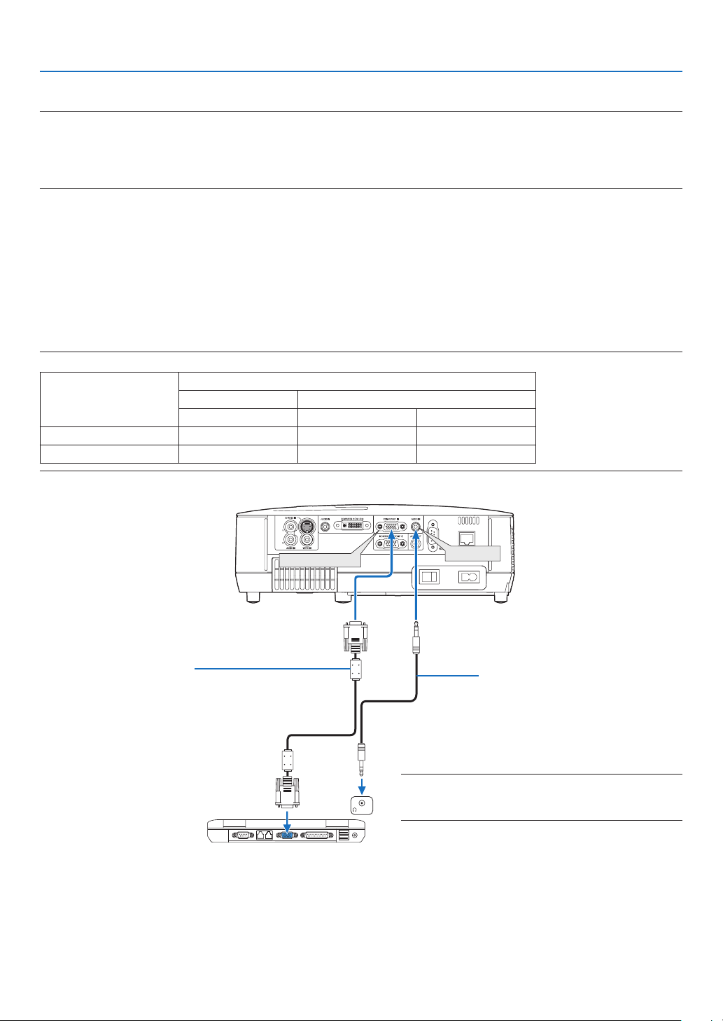
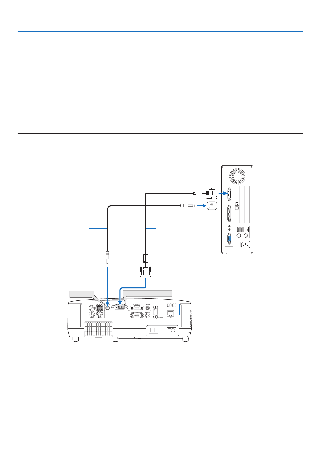
Connecting Your PC or Macintosh Computer
NOTE: Signals supported by Plug & Play (DDC2)
INPUT
Model
NP600/NP500/NP400 Yes No Yes
NP500W Yes Yes Yes
COMPUTER 1 IN COMPUTER 2 IN
analog analog digital
-
VGA signal cable (supplied)
To mini D-Sub 15-pin connector on the projector. It is
recommended that you use a commercially available distribution amplifier if connecting a signal cable longer than
the cable supplied.
IBM VGA or Compatibles (Notebook
type) or Macintosh (Notebook type)
Audio cable
(not supplied)
NOTE: For older Macintosh, use a commercially available
pin adapter (not supplied) to connect to your Mac’s video
port.
13

2. Installation and Connections
• Select the source name for its appropriate input connector after turning on the projector.
Input connector
COMPUTER 1 IN COMPUTER1 (COMPUTER 1)
COMPUTER 2(DVI-I)IN
NOTE: The projector is not compatible with video decoded outputs of the NEC ISS-6020 switcher.
NOTE: An image may not be displayed correctly when a Video or S-Video source is played back via a commercially available scan
converter.
This is because the projector will process a video signal as a computer signal at the default setting. In that case, do the following.
* When an image is displayed with the lower and upper black portion of the screen or a dark image is not displayed correctly:
Project an image to fill the screen and then press the AUTO ADJ. button on the remote control or the projector cabinet.
SOURCE button on the projector
cabinet
COMPUTER 2(DIGITAL)
or
COMPUTER 2(ANALOG)
Button on the remote control
(COMPUTER 2)
↓ (Toggle)
(COMPUTER 2)
14
2. Installation and Connections
COMPUTER 2 (DVI-I) IN
PHONE
AUDIO IN
When Viewing a DVI Digital Signal
To project a DVI digital signal, be sure to connect the PC and the projector using a DVI cable (not supplied) before
turning on your PC or projector. Turn on the projector first and select Computer 2 (Digital) from the source menu before
turning on your PC.
Failure to do so may not activate the digital output of the graphics card resulting in no picture being displayed. Should
this happen, restart your PC.
Do not disconnect the DVI cable while the projector is running. If the signal cable has been disconnected and then
re-connected, an image may not be correctly displayed. Should this happen, restart your PC.
NOTE:
• Use a DVI cable or the one compliant with the DDWG (Digital Display Working Group) DVI (Digital Visual Interface) revision 1.0
standard. The DVI cable should be within 5 m (196") long. Both single and dual types of DVI cable can be used.
• The DVI (DIGITAL) connector accepts VGA (640x480), SVGA (800x600), 1152x864, XGA (1024x768), WXGA (1280x800 @ up
to 60Hz), and SXGA (1280x1024 @ up to 60Hz).
IBM PC or Compatibles (Desktop type)
or Macintosh (Desktop type)
Audio cable (not supplied)
DVI cable (not supplied)
15
2. Installation and Connections
COMPUTER 1 IN
COMPUTER 2 (DVI-I) IN
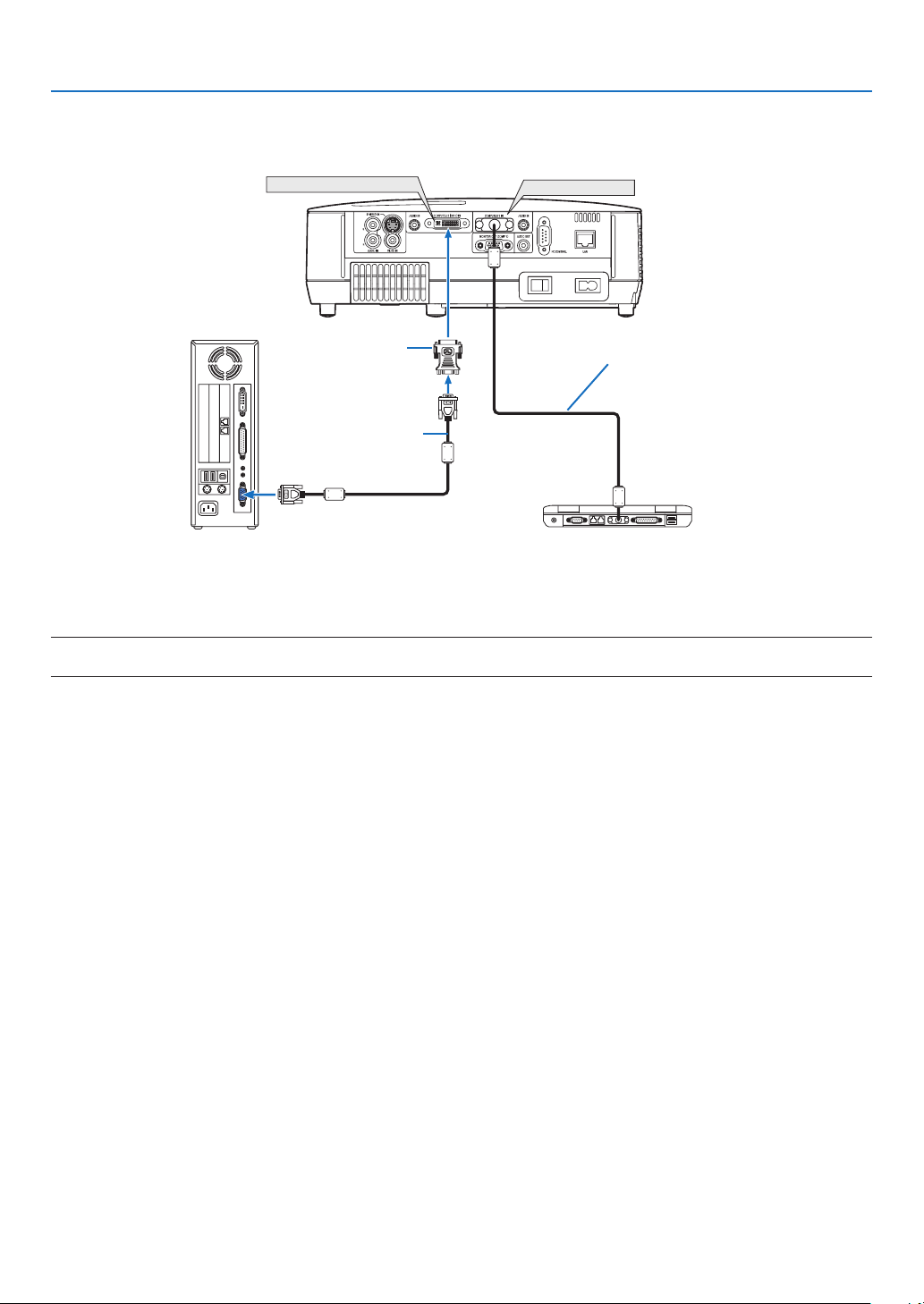
Using Two Analog COMPUTER Inputs Simultaneously
If you need to use two analog COMPUTER inputs simultaneously, connect a VGA signal cable as shown below.
IBM PC or Compatibles (Desktop
type) or Macintosh (Desktop type)
DVI to VGA adapter
(supplied)
VGA signal cable (not
supplied)
IBM PC or Compatibles (Notebook type)
or Macintosh (Notebook type)
VGA signal cable
(supplied)
NOTE: When the DVI to VGA adapter is not to be used for an extended period of time, remove it from the projector. Failure to do so
may cause damage to the connector of the projector.
16
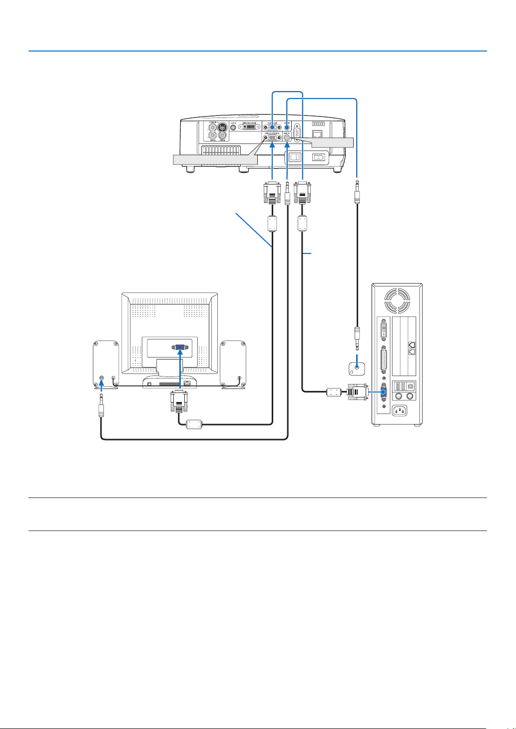
Connecting an External Monitor
AUDIO
IN
PHONE
MONITOR OUT (COMP 1)
AUDIO OUT
VGA signal cable (not supplied)
2. Installation and Connections
VGA signal
cable (supplied)
You can connect a separate, external monitor to your projector to simultaneously view on a monitor the computer
analog image you’re projecting.
NOTE:
• Daisy chain connection is not possible.
• When audio equipment is connected, the projector speaker is disabled.
17
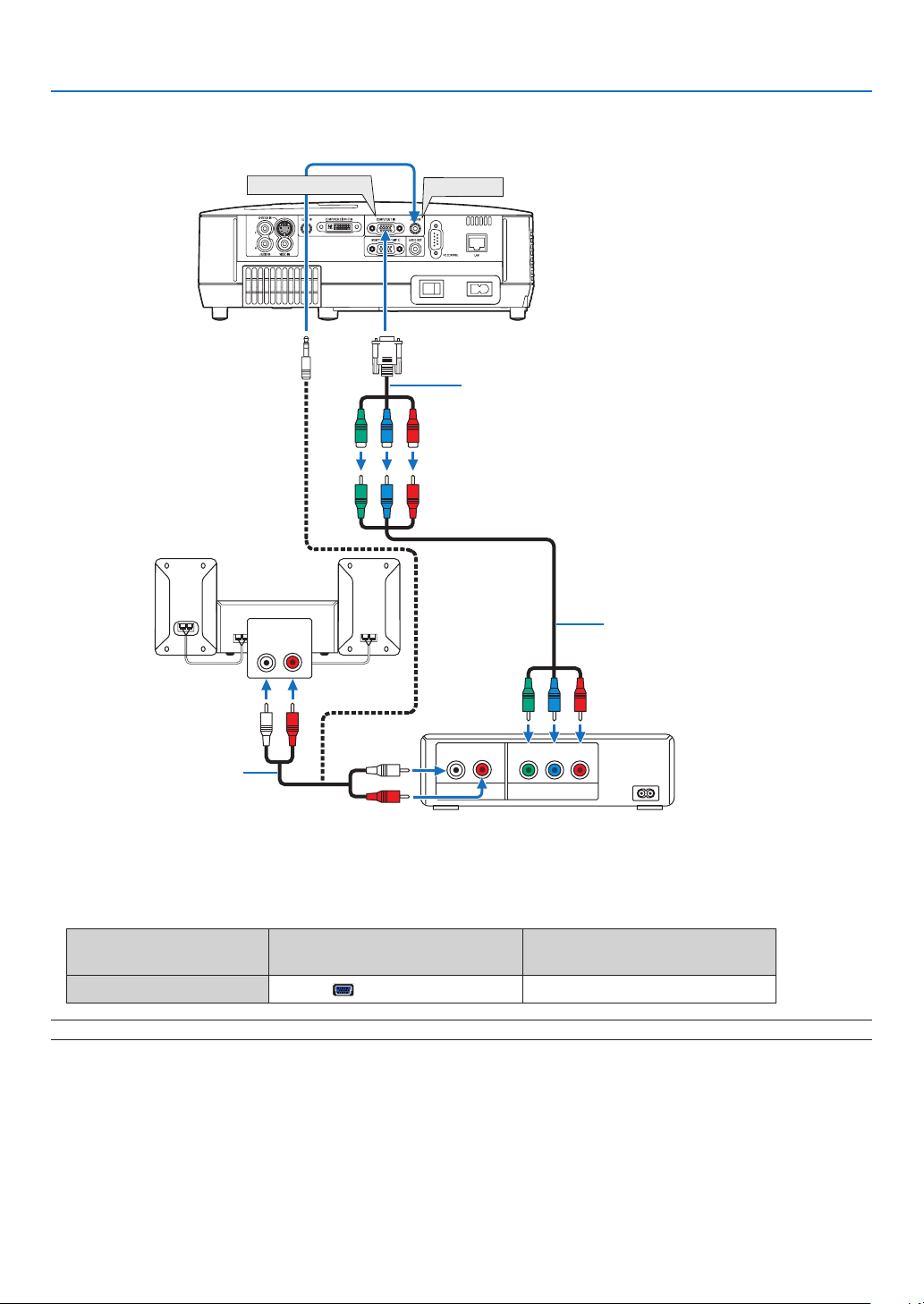
Connecting Your DVD Player with Component Output
AUDIO IN
L R
AUDIO OUT
L R
Component
Y Cb Cr
COMPUTER 1 IN
AUDIO IN
15-pin - to - RCA (female) 3 cable adapter
(ADP-CV1E)
Audio Equipment
2. Installation and Connections
Component video RCA3
cable (not supplied)
Audio cable (not supplied)
DVD player
A component signal will be automatically displayed. If not, from the menu, select [SETUP] → [OPTIONS(1)] →
[SIGNAL SELECT] → [COMPUTER1], and then place a check mark in the Component radio button.
• Select the source name for its appropriate input connector after turning on the projector.
Input connector
SOURCE button on the projector
cabinet
Button on the remote control
COMPUTER 1 IN COMPUTER1 (COMPUTER 1)
NOTE: Refer to your DVD player’s owner’s manual for more information about your DVD player’s video output requirements.
18
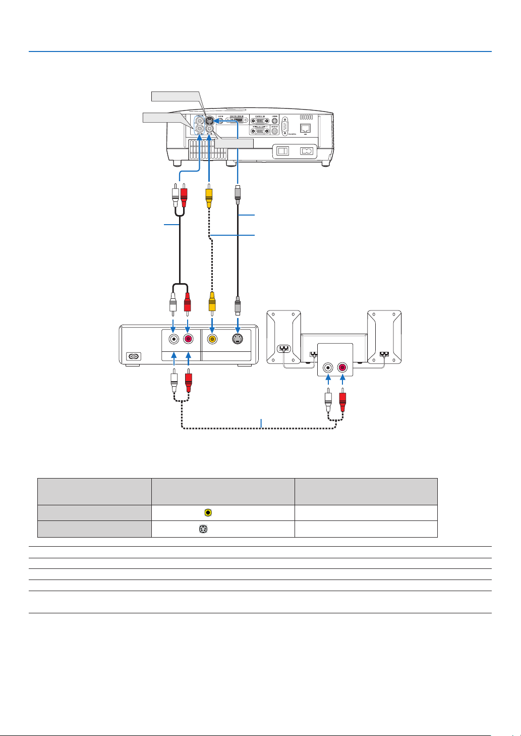
Connecting Your VCR
AUDIO IN
L R
AUDIO OUT
L R
VIDEO OUT
S-VIDEO VIDEO
S-VIDEO IN
AUDIO IN
VIDEO IN
2. Installation and Connections2. Installation and Connections
Audio cable (not supplied)
VCR
Audio cable (not supplied)
S-Video cable (not supplied)
Video cable (not supplied)
Audio equipment
• Select the source name for its appropriate input connector after turning on the projector.
Input connector
VIDEO IN
S-VIDEO IN
SOURCE button on the projector
cabinet
VIDEO
S-VIDEO
Button on the remote control
(VIDEO)
(S-VIDEO)
NOTE: The AUDIO IN L and R jacks (RCA) are shared between the Video and S-Video inputs.
NOTE: Refer to your VCR owner’s manual for more information about your equipment’s video output requirements.
NOTE: An image may not be displayed correctly when a Video or S-Video source is played back in fast-forward or fast-rewind via
a scan converter.
19
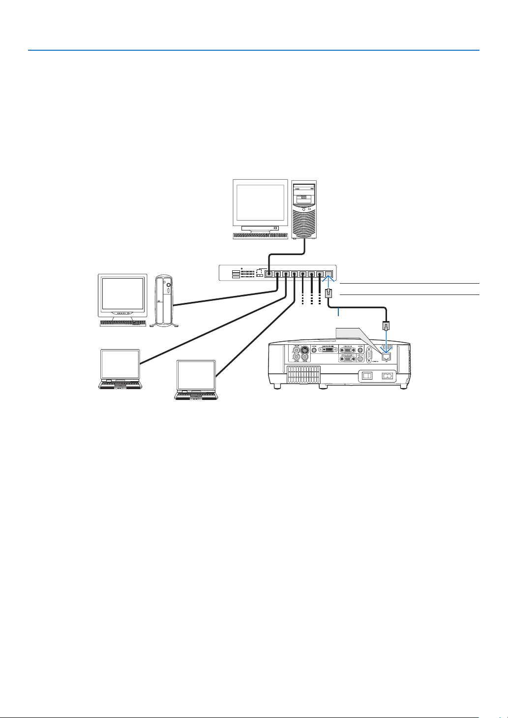
2. Installation and Connections
LAN
Connecting to a Network
The projector comes standard with a LAN port (RJ-45) which provides a LAN connection using a LAN cable.
Using a LAN cable allows you to specify the Network Settings and the Alert Mail Settings for the projector over a LAN.
To use a LAN connection, you are required to assign an IP address to the projector on the [PROJECTOR NETWORK
SETTINGS] screen of the web browser on your computer. For setting, see page 41,42,43.
Example of LAN connection
Example of wired LAN connection
Server
Hub
NOTE: Use a Category 5 or higher LAN cable.
LAN cable (not supplied)
20
2. Installation and Connections
S
E
L
E
C
T
M
E
N
U
E
X
I
T
E
N
T
E
R
S
T
A
TU
S
L
A
MP
A
U
T
O
A
D
J
.
S
O
U
R
C
E
F
O
C
U
S
STATUS
LAMP
AUTO ADJ.SOURCE
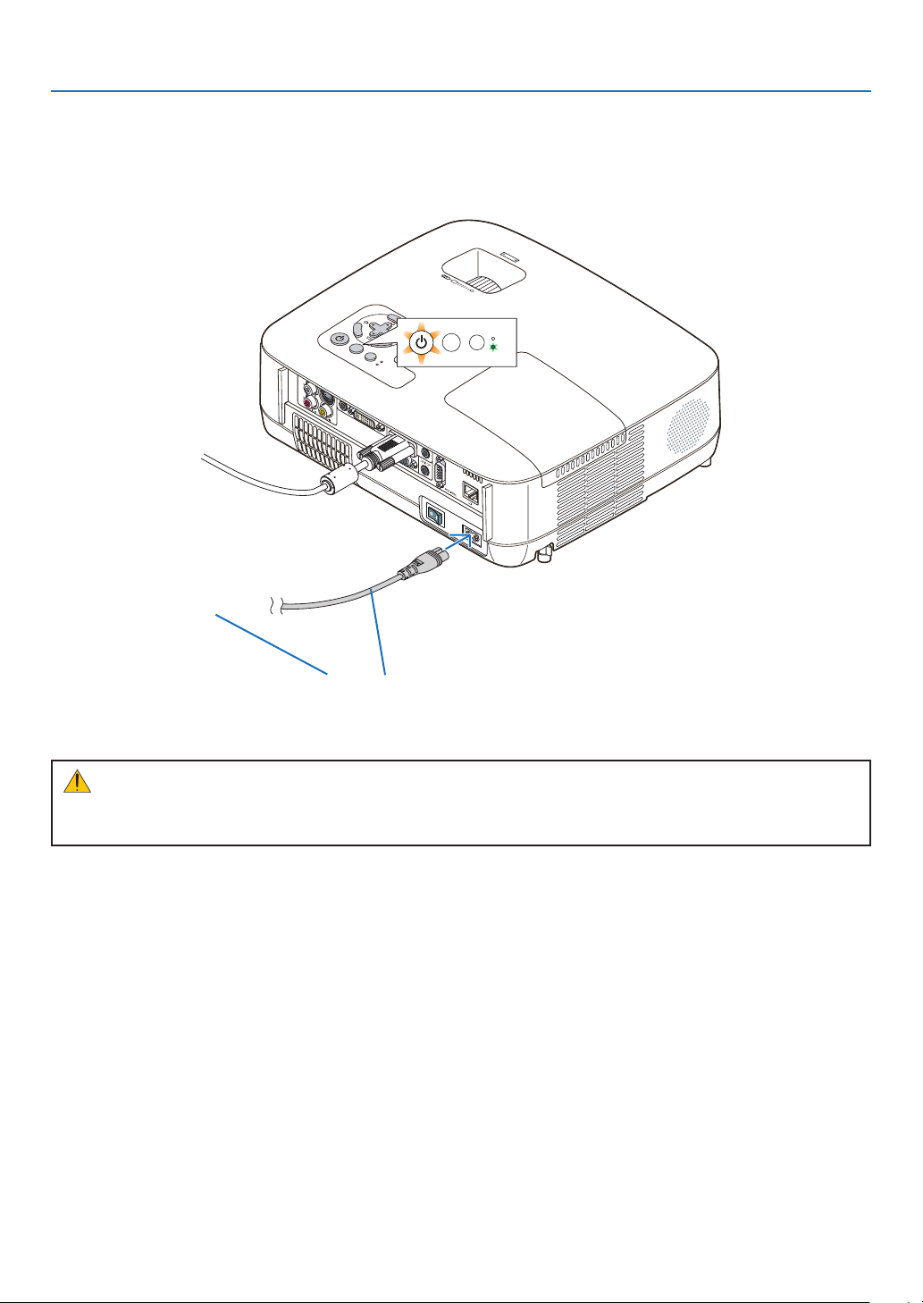
Connecting the Supplied Power Cable
Connect the supplied power cable to the projector.
First connect the supplied power cable’s two-pin plug to the AC IN of the projector, and then connect the other plug
of the supplied power cable in the wall outlet.
To wall outlet ←
Make sure that the prongs are fully inserted into both
the AC IN and the wall outlet.
CAUTION:
Do not try to touch the ventilation outlet on the left front (when seen from the front) as it can become heated while
the projector is turned on and immediately after the projector is turned off.
21
 Loading...