


A Powerful, Versatile Corporate PC
P
OWER
M
ATE
®
CT
SERVICE AND REFERENCE
MANUAL

Proprietary Notice and Liability Disclaimer
The information disclosed in this document, including all designs and related materials, is the valuable
property of NEC Computers Inc. (hereinafter “NECC”) and/or its licensors. NECC and/or its licensors, as
appropriate, reserve all patent, copyright and other proprietary rights to this document, including all design,
manufacturing, reproduction, use, and sales rights thereto, except to the extent said rights are expressly
granted to others.
The NECC product(s) discussed in this document are warranted in accordance with the terms of the Warranty
Statement accompanying each product. However, actual performance of each such product is dependent upon
factors such as system configuration, customer data, and operator control. Since implementation by customers
of each product may vary, the suitability of specific product configurations and applications must be
determined by the customer and is not warranted by NECC.
To allow for design and specification improvements, the information in this document is subject to change at
any time, without notice. Reproduction of this document or por tions thereof without prior written approval of
NECC is prohibited.
NEC is a registered trademark of NEC Corporation.
PowerMate and MultiSync are registered trademarks and VistaScan is a trademark of NEC Corpor ation or one of its
subsidiaries. All are used under license by NEC Corporation and/or one or more of its subsidiaries.
All other trademarks and registered t r ademarks are the property of their respecti ve t r ademark owners.
First Printing — August 2000
Copyright 2000
NEC Computers Inc.
15 Business Park Way
Sacramento, CA 95828
All Rights Reserved

Contents
Preface..................................................................................................................................ix
Abbreviations........................................................................................................................xi
1 System Overview
Configuration..................................................................................................................... 1-2
Features.............................................................................................................................. 1-4
Front Features............................................................................................................. 1-4
Rear Features.............................................................................................................. 1-5
Inside Features............................................................................................................ 1-8
Power Management Features...................................................................................... 1-9
Software Features..................................................................................................... 1-10
Preloaded Software............................................................................................ 1-10
NEC Product Recovery Program CD................................................................ 1-10
NEC PowerMate Driver CD.............................................................................. 1-10
Security Features ...................................................................................................... 1-11
Password Security ............................................................................................. 1-11
Windows Network Security Features................................................................ 1-11
Keyboard/mouse Anti-theft Bracket.................................................................. 1-11
Locking Tab ...................................................................................................... 1-11
Chassis Intrusion Notification........................................................................... 1-11
Hard Drive Password Protection....................................................................... 1-11
Components..................................................................................................................... 1-12
System Board............................................................................................................ 1-12
System Memory........................................................................................................ 1-13
Diskette Drive........................................................................................................... 1-13
Hard Drive................................................................................................................ 1-13
AGP Video Board..................................................................................................... 1-13
Power Supply............................................................................................................ 1-13
Keyboard .................................................................................................................. 1-13
Mouse....................................................................................................................... 1-14
CD-ROM Drive........................................................................................................ 1-14
DVD-ROM Drive..................................................................................................... 1-14
CD-RW Drive........................................................................................................... 1-14
Zip Drive .................................................................................................................. 1-14
Speakers.................................................................................................................... 1-14
Modem Board........................................................................................................... 1-15
Network Board ......................................................................................................... 1-15
2 System Configuration
Interrupt Requests..............................................................................................................2-2
System Interrupts........................................................................................................ 2-2
Parallel Port Interrupts................................................................................................ 2-3
Serial Port Interrupts................................................................................................... 2-4
Jumper Settings.................................................................................................................. 2-4
System Board Jumper Settings................................................................................... 2-4
Maxtor EIDE Hard Drive Jumper Settings................................................................. 2-7
Quantum EIDE Hard Drive Jumper Settings.............................................................. 2-7
CD-ROM Drive Jumper Settings................................................................................ 2-7
BIOS Setup Utility............................................................................................................. 2-8
How to Start Setup...................................................................................................... 2-8
How to Use Setup....................................................................................................... 2-9
Main Menu ............................................................................................................... 2-10
Advanced Menu........................................................................................................ 2-13
Security Menu........................................................................................................... 2-18
Power Menu.............................................................................................................. 2-20
Contents iii

Boot Menu................................................................................................................2-22
Exit Menu ................................................................................................................. 2-22
Hard Drive Security.........................................................................................................2-23
Establishing Hard Disk Drive Passwords .................................................................2-23
Changing Hard Disk Drive Passwords......................................................................2-23
Using Hard Disk Drive Password Protection............................................................ 2-24
Moving the Hard Drive............................................................................................. 2-24
FLASH Utility..................................................................................................................2-25
Online Documentation..................................................................................................... 2-25
Product Recovery Program.............................................................................................. 2-26
Starting the Recovery Program.................................................................................2-26
Using the Recovery Program....................................................................................2-27
Standard System Restore................................................................................... 2-27
Advanced Options ............................................................................................. 2-27
Tools.................................................................................................................. 2-28
Using the Smart Restore Program.............................................................................2-28
How to Load Smart Restore...............................................................................2-28
Software Restore or Removal............................................................................2-29
Hardware Settings..............................................................................................2-29
Restoration Process............................................................................................2-29
PowerMate Driver CD.....................................................................................................2-29
Intel Processor Serial Number Control Utility.................................................................2-29
System Requirements................................................................................................2-30
Installation ................................................................................................................ 2-30
Processor Serial Number...........................................................................................2-30
Frequently Asked Questions.....................................................................................2-30
Intel Technical Support.............................................................................................2-31
3 Disassembly and Reassembly
System Covers....................................................................................................................3-3
Removing the Cover...................................................................................................3-3
Replacing the Cover....................................................................................................3-4
Removing the Front Panel...........................................................................................3-5
Replacing the Front Panel...........................................................................................3-6
Expansion Boards ..............................................................................................................3-6
Removing the Retainer Bar.........................................................................................3-7
Removing an Expansion Board...................................................................................3-8
Installing a Slot Cover ................................................................................................ 3-9
Removing a Slot Cover...............................................................................................3-9
Installing an Expansion Board..................................................................................3-10
Replacing the Retainer Bar....................................................................................... 3-11
RIMM Memory Modules................................................................................................. 3-12
Removing a RIMM or Continuity Module...............................................................3-12
Installing a RIMM or Continuity Module................................................................. 3-14
Processor..........................................................................................................................3-16
Removing the Processor ........................................................................................... 3-16
Installing an Upgrade Processor ...............................................................................3-17
5 1/4-Inch Accessible Devices.........................................................................................3-18
Removing or Replacing a Bay Cover........................................................................3-19
Removing a Bay Cover......................................................................................3-19
Replacing a Bay Cover...................................................................................... 3-20
Storing and Retrieving Unused Rails........................................................................ 3-20
Removing or Installing Device Rails........................................................................3-21
Removing a 5 1/4-Inch Accessible Device...............................................................3-22
Installing a 5 1/4-Inch Accessible Device.................................................................3-23
3 1/2-Inch Accessible Devices.........................................................................................3-24
Removing a 3 1/2-Inch Accessible Device...............................................................3-24
Installing a 3 1/2-Inch Accessible Device.................................................................3-25
iv Contents

3 1/2-Inch Internal Drives................................................................................................ 3-26
Removing a 3 1/2-Inch Internal Drive...................................................................... 3-26
Installing a 3 1/2-Inch Internal Drive ....................................................................... 3-28
CMOS Battery................................................................................................................. 3-30
System Board................................................................................................................... 3-31
Removing the System Board.................................................................................... 3-31
Reinstalling the System Board.................................................................................. 3-32
Power Supply................................................................................................................... 3-33
Front USB Port................................................................................................................ 3-34
Front LED/Switch Bracket .............................................................................................. 3-34
Chassis Intrusion Switch.................................................................................................. 3-36
Minitower and Desktop Setup ......................................................................................... 3-37
Converting from Minitower to Desktop................................................................... 3-37
Converting from Desktop to Minitower................................................................... 3-38
Chassis Shell.................................................................................................................... 3-40
Replacing the Chassis Shell...................................................................................... 3-40
4 System Board
External Cable Connectors................................................................................................ 4-2
Internal Cable Connectors................................................................................................. 4-3
Jumper Settings.................................................................................................................. 4-4
Locating System Board Jumpers................................................................................ 4-4
Changing a Jumper Setting......................................................................................... 4-4
Upgrade Sockets................................................................................................................ 4-5
Processor Socket......................................................................................................... 4-6
RIMM Sockets............................................................................................................ 4-6
Checking System Memory......................................................................................... 4-7
Components....................................................................................................................... 4-7
Processor and Secondary Cache................................................................................. 4-9
System BIOS.............................................................................................................. 4-9
System Memory........................................................................................................ 4-10
Plug and Play............................................................................................................ 4-10
PCI/IDE Ports........................................................................................................... 4-10
Parallel Interface....................................................................................................... 4-10
Serial Interface.......................................................................................................... 4-11
USB Interface........................................................................................................... 4-12
Accelerated Graphics Port........................................................................................ 4-12
Integrated Audio....................................................................................................... 4-12
Resources......................................................................................................................... 4-13
Memory Map............................................................................................................ 4-13
I/O Addresses ........................................................................................................... 4-13
DMA Settings........................................................................................................... 4-15
5 Illustrated Parts Breakdown
Ordering Parts.................................................................................................................... 5-2
Field Replaceable Unit....................................................................................................... 5-2
Illustrated Parts Breakdown............................................................................................... 5-4
6 Preventive Maintenance
System Cleaning................................................................................................................ 6-2
Keyboard Cleaning............................................................................................................ 6-2
Mouse Cleaning................................................................................................................. 6-3
Contents v

7 Troubleshooting
Checklist ............................................................................................................................ 7-2
System Problems.........................................................................................................7-2
Diskette Drive Problems.............................................................................................7-3
Monitor Problems.......................................................................................................7-3
Keyboard/Mouse Problems.........................................................................................7-4
CD-ROM Drive Problems ..........................................................................................7-4
Speaker Problems........................................................................................................7-5
Diagnostics.........................................................................................................................7-6
8 NECC Information Services
Service Telephone Numbers..............................................................................................8-2
Technical Support.............................................................................................................. 8-2
NECC Website............................................................................................................8-2
NECC FTP Site........................................................................................................... 8-3
Email/Fax Technical Support Service......................................................................... 8-3
Technical Support Center ...........................................................................................8-3
9 Specifications
System Board Specifications..............................................................................................9-2
Keyboard Specifications....................................................................................................9-3
Mouse Specifications......................................................................................................... 9-3
Speaker Specifications....................................................................................................... 9-4
System Unit Specifications................................................................................................9-4
Hard Drive Specifications..................................................................................................9-5
Diskette Drive Specifications.............................................................................................9-8
CD-ROM Drive Specifications..........................................................................................9-8
CD-RW Drive Specifications.............................................................................................9-9
DVD-ROM Drive Specifications.......................................................................................9-9
Zip Drive Specifications ..................................................................................................9-10
Modem Board Specifications........................................................................................... 9-11
Network Board Specifications.........................................................................................9-11
ATX Power Supply Specifications ..................................................................................9-12
Environmental and Safety Specifications.........................................................................9-12
Compliance......................................................................................................................9-13
Glossary
Index
Regulatory Statements
vi Contents

List of Figures
PowerMate CT Minitower Front Features......................................................................... 1-4
PowerMate CT Desktop Front Features............................................................................. 1-4
PowerMate CT Minitower Rear Features.......................................................................... 1-6
Minitower Rear Connector Locations................................................................................ 1-6
PowerMate CT Desktop Rear Features.............................................................................. 1-7
Desktop Rear Connector Locations................................................................................... 1-7
Inside the System ...............................................................................................................1-8
System Board Jumper Block Locations............................................................................. 2-5
Setup Main Menu .............................................................................................................. 2-8
Locating the Cover Screws................................................................................................ 3-3
Removing the Cover.......................................................................................................... 3-4
Replacing the Cover........................................................................................................... 3-4
Removing the Front Panel................................................................................................. 3-5
Replacing the Front Panel.................................................................................................. 3-6
Locating Expansion Board Slots and Connectors.............................................................. 3-7
Removing the Expansion Board Retainer Bar................................................................... 3-7
Removing an Expansion Board......................................................................................... 3-8
Installing a Slot Cover....................................................................................................... 3-9
Installing an Expansion Board......................................................................................... 3-10
Replacing the Retainer Bar.............................................................................................. 3-11
Locating the RIMM and Processor Sockets..................................................................... 3-12
Removing a Continuity Module.......................................................................................3-13
Removing a RIMM Module ............................................................................................ 3-13
Installing a RIMM Module.............................................................................................. 3-15
Installing a Continuity Module........................................................................................ 3-15
Removing the Fan, Heat Sink, and Processor.................................................................. 3-17
Removing a 5 1/4-Inch Device Bay Cover...................................................................... 3-19
Replacing a Bay Cover.................................................................................................... 3-20
Storing an Unused Rail.................................................................................................... 3-21
Locating the Screws for 5 1/4-Inch Device Rails............................................................ 3-21
Releasing a 5 1/4-Inch Device......................................................................................... 3-22
Inserting a 5 1/4-Inch Device for Use in a Minitower ..................................................... 3-23
Removing the 3 1/2-Inch Accessible Device Bracket......................................................3-24
The 3 1/2-Inch Accessible Device Bracket...................................................................... 3-25
Locating the Internal Drive Bracket.................................................................................3-26
Locating Internal Drive Bracket Screws.......................................................................... 3-27
Sliding the Internal Drive Bracket out of the Chassis...................................................... 3-27
Locating Internal Drive Screws on the Bracket............................................................... 3-28
Locating Guides for the Internal Drive Bracket............................................................... 3-29
Securing the Internal Drive Bracket.................................................................................3-29
Locating the Battery on the System Board...................................................................... 3-30
Removing the Battery...................................................................................................... 3-31
Locating System Board Screws....................................................................................... 3-32
Locating the Power Supply Screws................................................................................. 3-33
Locating Front USB Port Screws..................................................................................... 3-34
Releasing the Front LED/Switch Bracket........................................................................ 3-35
Removing the Front LED/Switch Bracket....................................................................... 3-35
Removing the Chassis Intrusion Switch.......................................................................... 3-36
Accessible Device Placement for a Desktop.................................................................... 3-38
Accessible Device Placement for a Minitower................................................................ 3-39
Minitower External Cable Connector Locations................................................................4-2
Desktop External Cable Connector Locations................................................................... 4-3
System Board Internal Cable Connectors.......................................................................... 4-3
System Board Jumper Locations....................................................................................... 4-4
System Board Upgrade Sockets......................................................................................... 4-5
PowerMate CT System Illustrated Parts Breakdown......................................................... 5-4
Locating the Mouse Ball Cover......................................................................................... 6-3
Contents vii

List of Tables
PowerMate CT System Configuration............................................................................... 1-3
System Components.........................................................................................................1-12
Interrupt Level Assignments..............................................................................................2-2
Parallel Port Interrupts.......................................................................................................2-3
Serial Port Interrupts..........................................................................................................2-4
System Board Jumper Block Settings................................................................................2-5
Maxtor EIDE Hard Drive Jumper Settings........................................................................2-7
Quantum EIDE Hard Drive Jumper Settings..................................................................... 2-7
Setup Key Functions.......................................................................................................... 2-9
Main Menu Items.............................................................................................................2-10
Advanced Menu............................................................................................................... 2-14
Security Menu Items........................................................................................................ 2-18
Power Menu Settings.......................................................................................................2-20
Boot Menu Settings..........................................................................................................2-22
Exit Menu Items...............................................................................................................2-22
PowerMate CT System Disassembly Sequence ................................................................. 3-2
Sample RIMM Upgrade Paths...........................................................................................4-6
System Board Components................................................................................................ 4-8
Parallel Port Addresses ....................................................................................................4-11
Serial Port 1 and Serial Port 2 I/O Addresses ..................................................................4-11
System Memory Map....................................................................................................... 4-13
I/O Address Map.............................................................................................................. 4-13
DMA Settings ..................................................................................................................4-15
Ordering Parts.................................................................................................................... 5-2
PowerMate CT System FRU..............................................................................................5-2
Problems and Solutions......................................................................................................7-6
NECC Service and Support Telephone Numbers .............................................................. 8-2
System Specifications........................................................................................................9-2
System Board Specifications..............................................................................................9-2
Keyboard Specifications....................................................................................................9-3
Mouse Specifications......................................................................................................... 9-3
Speaker Specifications....................................................................................................... 9-4
System Unit Specifications................................................................................................9-4
Quantum Hard Drive Specifications..................................................................................9-5
Maxtor 5,400 RPM Hard Drive Specifications.................................................................. 9-6
Maxtor 7,200 RPM Hard Drive Specifications.................................................................. 9-7
Diskette Drive Specifications.............................................................................................9-8
NEC CD-ROM Drive Specifications................................................................................. 9-8
CD-RW Drive Specifications.............................................................................................9-9
DVD-ROM Drive Specifications.......................................................................................9-9
Zip Drive Specification....................................................................................................9-10
Modem Board Specifications........................................................................................... 9-11
3Com 3C905C Network Board Specifications ................................................................ 9-11
Intel PRO 100+ WOL Network Board Specifications.....................................................9-12
Power Supply Specifications............................................................................................9-12
Environmental and Safety Specifications.........................................................................9-12
System Compliance..........................................................................................................9-13
viii Contents

Preface
This manual contains technical information for servicing and r epairing the NEC PowerMate
CT systems manufactured by NEC Computers Inc. Use this manual for NEC PowerMate CT
computers assembled in Europe. Check the regulatory sticker at the rear of the system to find the
assembly location for the computer.
The manual contains hardware and interface information for users who need an overview of
system design. The manual includes system setup information, disassembly procedures, and an
illustrated parts list. The manual is prepared for NECC-trained customer engineers and support
center personnel.
The manual is organized as follows.
Section 1 — System Overview, provides an overview of system features and includes brief
descriptions of system components.
Section 2 — System Configuration, includes information on system IRQs, jumpers, and BIOS.
The section also contains information on power management features and system utilities,
including the BIOS FLASH Utility and PowerMate Product Recovery Program.
Section 3 — Disassembly and Re assembly, provides system disassembly and reassembly
procedures. Each procedure is supported by disassembly illustrations.
Section 4 — System Board, includes information on cable and board connector locations,
jumper settings, and upgrade sockets. Also provided is information on board components.
Section 5 — Illustrated Parts Breakdown, includes an exploded view diagram (illustrated
parts breakdown) and a parts list for field-replaceable parts.
®
Section 6 — Preventive Maintenance, provides recommended maintenance information for
maintaining the system in top condition.
Section 7 — Troubleshooting, includes information for solving possible system problems and
their solutions.
Section 8 — NECC Information Services, lists telephone numbers for obtaining service. The
section also includes information on NECC technical support and website.
Section 9 — Specifications, provides specifications for the major components in the system,
including the system board, power supply, diskette drive, hard drive, and CD-ROM drive.
Preface ix

Abbreviations
Aampere
AC alternating current
ACK acknowledge
AGP accelerated graphics port
AMR audio modem riser
ASIC application-specific integrated circuit
AT advanced technology (IBM PC)
ATA AT attachment
ATAPI AT attachment packet interface
ATM asynchronous transfer mode
BBS Bulletin Board Service
BCD binary-coded decimal
BCU BIOS Customized Utility
BIOS basic input/output system
bit binary digit
BUU BIOS Upgrade Utility
bpi bits per inch
bps bits per second
C capacitance
C centigrade
Cache high-speed buffer storage
CAM constantly addressable memory
CAS column address strobe
CD-ROM compact disk-ROM
CD-RW compact disk rewritable
CH channel
clk clock
cm centimeter
CMOS complementary metal oxide
semiconductor
COM communication
CONT contrast
CPGA ceramic pin grid array
CPU central processing unit
DAC digital-to-analog converter
DACK DMA acknowledge
dB decibels
DC direct current
DCC direct cable connection
DCE data communications equipment
DDC Display Data Channel
DIMM Dual In-Line Memory Module
DIP dual in-line package
DMA direct memory access
DMAC DMA controller
DMI Desktop Management Interface
DOS disk operating system
dpi dots per inch
DRAM dynamic RAM
DVD digital versatile disc
ECC error checking and correction
ECP extended capabilities port
EDO extended data output
EGA Enhanced Graphics Adapter
EIDE Enhanced IDE
EISA enhanced ISA
email electronic mail
EMI electromagnetic interference
EPP enhanced parallel port
EPROM erasable and programmable ROM
ESD electrostatic discharge
EVGA Enhanced Video Graphics Array
F Fahrenheit
FAX facsimile transmission
FCC Federal Communications Commission
FG frame ground
FM frequency modulatio n
FP fast page
FRU field-replaceable unit
ftp file transfer protocol
GB gigabyte
GND ground
HEX hexadecimal
HGA Hercules Graphics Adapter
Hz hertz
IC inte grated circuit
ID identification
IDE intelligent device electronics
IDTR interrupt descriptor table register
in. inch
INTA interrupt acknowledge
I/O input/output
IPB illustrated parts breakdown
IPC integrated peripheral controller
ips inches per second
IR infrared
Abbreviations xi

IrDA Infrared Data Association
IRR Interrupt Request register
ISA Industr y St andard Archi tecture
ISP internet service provider
IRQ interrupt request
K kilo (1024)
k kilo (1000)
KB kilobyte
Kbps Kilobits per second
kg kilogram
kHz kilohertz
lb pound
LAN local area network
LED light-emitting diode
LDCM LANDesk Client Manager
LSB least-significant bit
LSI large-scale integration
M mega (million)
mA milliamps
max maximum
MB megabyte
MFM modified frequency modulation
MHz megahertz
MIDI musical instrument digital interface
mm millimeter
MMX multimedia extensions
modem modulator/demodulator
MOS metal-oxide semiconductor
MPEG Motion Picture Experts Group
ms millisecond
MSB most-significant bit
NC not connected
NIC networked information center
NIC network interface card
NMI Non-maskable Interrupt
ns nanosecond
NSRC National Service Response Center
OCR optical character recognition
OS operating system
PAL programmable array logic
PC personal computer
PCB printed circuit board
PCI Peripheral Component Interconnect
PDA personal digital assistant
PFP plastic flat package
PIO parallel input/output
pixel picture element
PLCC plastic leaded chip carrier
PLL phase lock loop
POST Power-On Self-Test
p-p peak-to-peak
PPI programmable peripheral interface
PROM programmable ROM
PS/2 personal system/2
QFP quad flat pack
R read
RAM random-access memory
RAMDAC RAM digital-to-analog converter
RAS row address strobe
RDRAM
®
Rambus® dynamic RAM
RGB red green blue
RGBI red green blue intensity
RIMM Rambus inline memory module
rms root mean square
ROM read-only memory
rpm revolutions per minu te
RTC real-time clock
R/W read/write
Sslave
SCSI Small Computer System Interface
SDRAM synchronous dynamic RAM
S.E.C. single edge contact cartridge
S.E.P.P. single edge processor package
SG signal ground
SGRAM synchronous graphics RAM
SIMM single inline memor y module
SMART Self-Monitoring, Analysis and
Reporting Technology
S/N sig nal to no ise r a tio
SNMP simple net wor k management pro to co l
SPM standard page mode
SRAM static random access memory
SRS So und Retrieval System
SSI small scale integration
SVGA Super Video Graphics Array
SW switch
T&D test and diagnostics
TSC Technical Support Center
TTL transistor/transistor logic
tpi tracks per inch
xii Abbreviations

UART universal asynchr onous
receiver/transmitter
UHF ultra high frequency
UL Underwriter’s Laboratories
UMA unified memory architecture
UPS uninterruptible power supply
URL uniform resource locator
USB universal serial bus
Vvolt
Vac volts, alternating current
VCR video cassette recorder
Vdc volts, direct current
VDT video display terminal
VESA video electronics standards
association
VFC VES A-compliant feature connector
VGA Video Graphics Array
VHF very high fr e que nc y
VLSI very large scale integration
VRAM video RAM
Wwatt
WAN wide area network
WRAM Windows RAM
W write
www world wide web
Abbreviations xiii

System Overview
!
Configurations
!
Features
!
Components
1

This section provides an overview of the NEC PowerMate® CT system. Included are
descriptions of the system’s
hardware configuration
!
front, back, and inside features
!
security features
!
major components
!
software.
!
The system can be configured as a minitower or as a desktop to suit the user’s requirements.
Configuration
The NEC PowerMate CT system is a built-to-order system for commercial offices. System
features include an Intel
®
Pentium III processor, the Intel 820 chipset, two Rambus® inline
memory module (RIMM™) sockets, Rambus dynamic random access memory (RDRAM), and
a plug and play input/output (I/O) controller.
The system also features two universal serial bus (USB) ports, two serial ports, a parallel port, a
MIDI/game port, and audio ports. Ultra direct memory access (DMA), remote wakeup (“WakeOn LAN”), accelerated graphics port (AGP), audio modem riser (AMR), and power
management are supported.
Build choices include enhanced intelligent device electronics (EIDE) hard drives ranging from
10 gigabytes (GB) to 30 GB and higher. All drives feature Ultra DMA/66 and Self-Monitoring,
Analysis and Reporting Technology (SMART).
System memory is provided in 64-MB (minimum), 128-MB, or 256-MB RIMM modules.
Memory configurations range from 64 MB to 512 MB.
Additional build choices include a speaker set, LAN board, sound board, modem board, and
peripheral devices such as a 40X or higher CD-ROM drive, an 12X or higher DVD-ROM drive,
an 8x4x32x CD-ReWritable (RW) drive, an 8-MB or higher AGP video board, and a 250-MB
capacity Zip
®
drive.
The following table summarizes the PowerMate CT system configuration.
1-2 Overview

PowerMate CT System Configuration
Component Description
System Board Gigabyte GA-6CX7
Pentium III Processor* 667-MHz or higher, 133-MHz or higher FSB
Pentium III L1 Cache 32 KB SRAM integrated on processor
Pentium III L2 Cache 256 KB Pipeline Burst SRAM
Processor Mount Socket 370
System RAM* 64 MB (minimum) to 512 MB of up to PC800 RDRAM in 2 RIMM
sockets
Chip Set Intel 820 with 82820 Memory Controller Hub, 82801AA I/O
Controller Hub, 82802AA Firmware Hub, Audio-Codec 97
Controller, and System Manageability Bus
Winbond Super I/O
Controller
Winbond Super I/O Controller W83627HF-AW for parallel, serial,
keyboard, mouse, hardware monitor, diskette drive
Hard Drive* Ultra DMA/66, with SMART technology: 10-GB or higher,
5400 rpm or higher
Graphics Memory* 8-MB or higher, depending on AGP video board
Audio Yamaha Sound YMF 752-S
Diskette Drive 3.5-inch 1.44-MB
Power Supply 235-watt
Keyboard
Win 95-enhanced, PS/2
®
-compatible
Mouse 3-button mouse, PS/2-compatible
CD-ROM Drive* 40X or higher CD-ROM drive
DVD-ROM Drive* 12X or higher DVD-ROM drive
CD-RW Drive* 8x4x32x (8x record, 4x rewrite, 32x read)
Zip Drive* 250-MB Capacity Iomega Zip Drive
PCI Connectors System board support for up to five PCI expansion boards
LAN Board* 3Com PCI Ethernet 10/100 3C905C TX-M, Intel PCI Ethernet
Pro 100+ 10/100 with Wake-On LAN, Accton PCI Ethernet
10/100 TX4 or TX5
Video Board* 8-MB AGP 4x nVidia™ Vanta™ video board or 32-MB AGP 4x
nVidia TnT2™ Pro video board
Speakers* NEC 10-watt, with AC power adapter
* Built-to-order component
Overview 1-3

Features
The system front, back, and inside features are described in the following paragraphs. Also
included are descriptions of system security features.
Front Features
The PowerMate CT system can be used as a minitower or as a desktop. The following figures
show the features on the front of the system for both setups. Brief descriptions of the features
follow the figure.
PowerMate CT Minitower Front Features
A
– USB Port
B – CD-ROM Drive G – Power/Sleep Lamp
C – 5 1/4-Inch Bay H – Disk Activity Lamp
D – Diskette Drive I – Bracket for 3 1/2-Inch Accessible Devices
E
– 3 1/2-Inch Accessible Device Bay
F
– Power/Sleep Button
PowerMate CT Desktop Front Features
A – Power/Sleep Button F – Bracket for 3 1/2-Inch Accessible Devices
B – CD-ROM Drive G – 3 1/2-Inch Accessible Device Bay
C – 5 1/4-Inch Bay H – Diskette Drive
D – Power/Sleep Lamp I – USB Port
E – Disk Activity Lamp
1-4 Overview

The system has the following devices, controls, and lamps at the front of the system (see the
above figures for device, control, and lamp locations).
Power/sleep button — press this button to turn on system power. To turn off power, close
!
all applications, shut down Windows
power down the system. For Windows NT
®
; Windows 98 and Windows 2000 automatically
®
, close all applications, shut down Windows NT,
and press in the power button until the system powers down (approximately four seconds).
Press and immediately release the power button to suspend system operation and go into the
power saving mode. If a VESA-compliant monitor is in use, the monitor also goes into a
power-saving mode.
Press any key or move the mouse to exit the power saving mode and resume system
operation.
Power/sleep lamp — indicates if system power is on or off. Also indicates if the system is
!
operating in a power saving mode.
A steady green lamp indicates that power is on. An amber lamp and a blank screen indicates
that the system is in a sleep mode with full power reduction.
Hard drive lamp — when blinking, indicates that the hard drive is active. A blinking lamp
!
indicates that the hard drive is reading or writing data.
CD-ROM drive — load and start programs from a compact disc (CD) and to play audio
!
CDs. Controls and indicators include a CD tray open button, drive activity lamp, and
emergency tray open feature. Controls for an optional DVD-ROM drive are similar.
DVD-ROM drive — DVD-ROM drives offer many improvements over the standard
!
CD-ROM technology, including superior video and audio playback, faster data access, and
greater storage capacities.
The DVD-ROM drive uses DVD technology to read DVD discs as well as standard audio
and video CDs.
CD-RW drive — use the drive to read and write data on a CD-RW disc many times, just
!
like you would with a diskette, Zip disk, or hard drive.
Zip drive — use the Zip drive with 3 1/2-inch Zip disks to back up work, archive old files,
!
and transport work. The Zip drive supports both 250-MB and 100-MB Zip disks.
Diskette drive — copy data files to and from a diskette or use as a bootable drive for
!
loading and starting programs from a diskette. Controls and indicators include a diskette
eject button and drive activity lamp.
USB port — use this port to connect up to 127 universal serial bus (USB) devices without
!
opening the system. A second port is on the rear of the system.
Rear Features
The rear of the system contains external connectors and ports, a system power socket, a monitor
power socket, a voltage switch, expansion board slots, and security features.
The following figures show minitower and desktop features. Br ief descr iptions of each item
follow the figure. See the next two sections for information about the connectors and the power
supply. See “Expansion Boards” in Section 3 for information about expansion board slots. See
“Security Features” later in this section for information on security features.
Overview 1-5

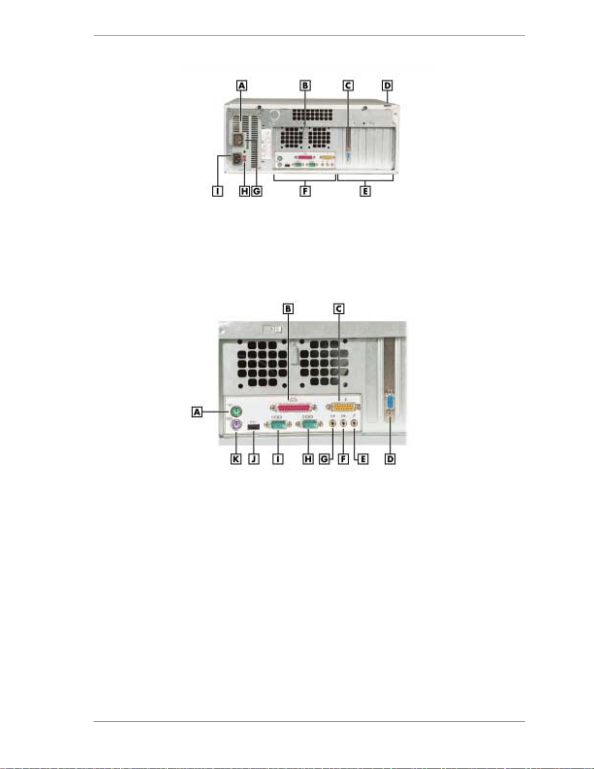
PowerMate CT Mi nitower Rear Features
A – AC Power Connector F – Locking Tab
B – Monitor Power Socket G – Expansion Slots
C – Power Supply H – System Board Connectors
D
– Keyboard/Mouse Anti-Theft BracketI – Voltage Switch
E – AGP Video Board
Minitower Rear Connector Locations
A – Keyboard Connector G – Line In
B – Mouse Connector H – Line Out
C – Parallel Port I – Serial Port 2
D – MIDI/Game Port J – Serial Port 1
E – VGA Connector K – USB Port
F – Microphone In
1-6 Overview
PowerMate CT Desktop Rear Features
A – Power Supply F – System Board Connectors
B – Keyboard/Mouse Anti-theft Bracket G – Monitor Power Socket
C – AGP Video Board H – Voltage Switch
D – Locking Tab I – AC Power Connector
E
– Expansion Slots
Desktop Rear Connector Locations
A – Mouse Connector G – Line Out
B
– Parallel Port
C – MIDI/Game Port I – Serial Port 1
D – VGA Connector J – USB Port
E – Microphone In K – Keyboard Port
F
– Line In
H
– Serial Port 2
The rear of the system has the following external ports, connectors, jacks, and expansion slots.
Keyboard port — attach a PS/2®-compatible (personal system/2-compatible) keyboard
!
(101-key or 102-key) with a 6-pin mini DIN connector to this port.
Mouse port — attach a PS/2-compatible mouse to this port.
!
Printer port — attach a parallel printer with a 25-pin connector to this por t.
!
USB port — use the USB port to connect up to 127 USB configured peripheral devices such
!
as a printer, monitor, modem, mouse, and scanner. A second USB por t is on the front of the
system.
Serial ports — serial port 1 (COM1) and serial port 2 (COM2) allow connection of serial
!
devices with 9-pin connectors. The devices include a pointing device, serial printer, or
modem.
Overview 1-7

VGA monitor connector — attach a video graphics array (VGA)-compatible monitor (NEC
!
MultiSync
connector on the installed video board.
Monitor power socket — if a plug adapter is available, connect the power cord from the
!
monitor to the monitor power socket to use fewer wall or surge protector outlets.
Microphone in jack — use this jack to connect a microphone for recording audio
!
information in data system files.
Line in jack — use this jack to connect a stereo audio device such as a stereo amplifier or a
!
cassette or minidisc player for playback or recording.
Line out jack — use this jack to connect an amplified output device, such as powered
!
speakers or headset, a stereo tape recorder, or an external amplifier for audio output.
MIDI/joystick — use this connector to attach a joystick to the system for use with games.
!
Expansion board slots — use these slots to in stall up to five optional PCI boards (grap hics,
!
LAN, modem, sound).
Inside Features
The following figure shows the interior of the system and its major areas. A list of features
follow the figure.
®
monitor or other VGA-compatible monitor) with a 15-pin connector to the AGP
Inside the System
A – Power Supply F – PCI Expansion Board Connectors
B – System Board G – AGP Video Board
C – RIMM Memory Sockets H – AMR Connector
D – Accessible Device Cage I – Processor
E – Internal Drive Bracket
1-8 Overview

The inside of the system has the following features:
system board — contains the Pentium processor Socket 370 connector, two RIMM memory
!
sockets, two IDE connectors, five PCI board connectors, an AGP board connector, an AMR
board connector, diskette drive connector, system configuration jumpers, internal signal and
power connectors, and external device connectors
5 1/4-inch accessible device cage — has two accessible 5 1/4-inch slots for the
!
CD-ROM drive or DVD-ROM drive and another 5 1/4-inch device
3 1/2-inch accessible device cage — contains two accessible 3 1/2-inch slots, one of which
!
houses the 1.44-MB diskette drive
internal drive bracket — has three 3 1/2-inch internal device slots, one of which houses the
!
standard hard drive
expansion slots — provide five PCI board expansion slots, one of which houses the
!
standard AGP video board
235-watt power supply — is switch selectable, 115 Vac or 230 Vac.
!
For more information on the above features, see “Components” in this section.
Power Management Features
The system comes with Adva nced Power Management ( APM) and Advanced Configuration and
Power Interface (ACPI). Included as a subset to ACPI is Instantly Available Technology.
APM features Soft Power Off, which automatically powers down the system when exiting
Windows 98 or Windows 2000 (not available for Windows NT). This feature is enabled or
disabled through the system’s BIOS (see Section 2, “System Configuration,” for Power
Management BIOS settings).
Instantly Available Technology features the ACPI sleep mode which maximizes power savings.
When in the sleep mode, the system appears to be off. The power supply and fans are off and the
power lamp is amber. Pressi ng a key or moving the mouse instantly wakes up the system and
returns it to where it was before going into the sleep mode. This feature is enabled or disabled by
setting jumpers on the system board (see Section 2, “System Configuration” for information on
setting system board jumpers).
If the system has an optional internal or external modem installed, the Wake On Ring (WOR)
and Resume On Ring (ROR) features of the system can be used. With WOR, the system can be
powered up through the modem from either the Soft Power Off or ACPI modes. The first call
through the modem powers on the system and the second call allows access to your system.
The ROR feature allows a single call on the modem to resume system oper a tion and to allow
system access. The ROR feature can be used while the system is in the sleep mode or the ACPI
power on state.
See Section 2, “System Configuration” for information on setting the WOR and ROR feature s
through the system’s BIOS. In addition, for the WOR feature, a cable must be connected to a
modem and to the WOR connector on the system board.
Overview 1-9

Software Features
NECC provides a variety of applications and hardware utilitie s with the system to let you take
advantage of the system hardware capabilities.
Preloaded Software
The system comes preloaded with the Microsoft® Windows® 98 operating system or the
Windows 2000
/Windows NT® operating system configuration.
If you have a Windows 2000/Windows NT configuration, you must choose the operating system
you want to load. The operating system you choose is your only ope rating system and is the one
that the Product Recovery Program restores.
NECC-provided applications, drivers, and utilities come loaded o n the hard drive. You ca n
install some of the applications from icons on the Wi ndows desktop. Software available on the
system includes the following applications:
Microsoft Internet Explorer
!
Internet Explorer provides a top-notch browser with preloaded links for easy access to the
world wide web. Also use Internet Explorer to access one of the many new browser-based
utilities.
Norton AntiVirus™ 2000 Software
!
Protect the syste m from viruses by running Norton’s virus scan software.
Adobe® Acrobat® Reader
!
Use the Adobe Acrobat Reader to read and print portable document format (PDF) files
found on the Internet and PDF documents included with various software applications.
Online Documentation
!
Get quick access to comprehensive information about your system in the online
PowerMate CT User’s Guide. See “Online Documentation” in Section 2 for a description of
the documentation and how to use it.
Intel LANDesk® Client Manager
!
Use LANDesk software to track system information such as serial number, BIOS version,
memory capacity, disk capacity, expansion board settings, and applications. Use LANDesk
software for remote starts from a server computer using Wake-On LAN and remote boot.
NEC Product Recovery Program CD
The system comes with an NEC Product Recovery Program CD and bootable diskette. Should a
problem occur that causes data loss or corruption, you can use the NEC Product Recovery
Program CD to restore the system to its original factory state or you can restore just the
operating system and drivers. A full system resto re loads the operating system and all the
factory-supplied software that comes on the hard drive. See “Product Recovery Program” in
Section 2 for information about using the restore options.
NEC PowerMate Driver CD
Use the NEC PowerMate Driver CD to install drivers for NEC system options that are not part
of the factory configuration. Also use the NEC PowerMate Driver CD to reinstall
NECC-supplied software. See “PowerMate Driver CD” in Section 2 for information about
installing drivers from the CD.
1-10 Overview

Security Features
The system has hardware, software, and mechanical security features that offer protection
against unauthorized access to the system and data. The following security features are
available.
Password Security
The BIOS Setup Utility includes a feature that allows a user to set either a user or supervisor
password, or both.
The user password controls booting of the system and controls access to the Setup Utility and
the keyboard. User access to the BIOS Setup Utility is limited when a supervisor password is
set. The supervisor password allows full access to the system and the BIOS.
See Section 2, “System Configuration,” for further i nformation on setting and using passwords.
Windows Network Security Features
The Windows Network Security feature is available through the Wind ows operating system.
Check the Windows documentation for details.
Keyboard/mouse Anti-theft Bracket
The keyboard/mouse anti-theft bracket secures the keyboard and mouse cables to the system,
making it difficult to remove the keyboard and mouse from the system.
Locking Tab
The system has a locking tab on the rear of the system. The tab fits through a mating slot in the
rear edge of the chassis cover. Securing a padlock (not supplied) in the locking tab prevents
removal of the system cover and access to the interior of the system.
Chassis Intrusion Notification
Whenever the system cover is removed, a hidden switch (if installed) sends a signal to the
LANDesk Client Manager (LDCM). LDCM logs the incident and then reports it o n screen the
next time the system is rebooted.
Hard Drive Password Protection
The system supports password protection for the hard drive. Hard drive password protection
restricts access to the drive if the drive is removed and installed in another system. The system
does not prompt for hard drive passwords while the drive remains in the current system.
The passwords are written to the system BIOS and to the hard drive to ensure that the password
protection travels with the drive if it is moved to another system. See Section 2, “Sys tem
Configuration,” for additional information on using hard drive security.
Overview 1-11

Components
The major system components are listed in the following table, along with the page number
where each component is briefly described.
System Components
Component Go to Page
System Board 1-12
System Memory 1-13
Diskette Drive 1-13
Hard Drive* 1-13
AGP Video Board* 1-13
Power Supply 1-13
Keyboard 1-13
Mouse 1-14
CD-ROM Drive* 1-14
DVD-ROM Drive* 1-14
CD-RW Drive* 1-14
System Board
The system processor, memory, system battery, internal connectors, and most external
connectors are housed on the system board. For information on the external connectors, see
“External Connectors” earlier in this chapter.
The system board supports one diskette drive and up to four IDE devices such as hard drives, a
CD-ROM drive, a DVD-ROM drive, a CD-RW drive, or a Zip drive.
Internal connectors on the system board include:
primary and secondary IDE connectors with Ultra DMA/66 support
!
one diskette drive connector
!
one processor socket
!
front panel connectors for system lamps and USB
!
power connectors
!
Zip Drive* 1-14
Speakers* 1-14
Modem Board* 1-15
Network Board* 1-15
* Built-to-order component
!
!
!
!
For further information on the system board, see Section 4, “System Bo ards.”
1-12 Overview
two RIMM sockets
five PCI connectors
one AGP connector
one AMR connector.

System Memory
The system supports up to 512 MB of high-speed non-ECC or ECC RDRAM memory in two
RIMM sockets on the system board. Supported are 184-pin, PC800-MHz modules in
64-, 128-, and 256-MB unbuffered configurations.
The RIMM modules can be installed in one or two sockets and can vary in size between sockets.
If only one RIMM module is installed, a continuity module must be installed in the empty
socket.
Diskette Drive
A single diskette drive is supported in the system. The installed 1.44-MB 3 1/2-inch diskette
drive is connected by a ribbon cable with two connectors. The diskette drive cable plugs directly
into the system board. There are no switches or jumpers that need to b e set and the diske tte drive
is terminated.
Diskette drive specifications are given in Section 9, “Specifications.”
Hard Drive
All systems ship with one internal 3 1/2-inch EIDE hard installed inside the system, under the
CD-ROM drive. Drives are available in 10-GB or higher Ultra DMA/66 models.
An Ultra DMA/66 cable connects the hard drive to the primary IDE channel on the system
board. The drive is connected as the master device on the primary channel.
Hard drive jumper settings are given in Section 2, “System Configuration.” The location of the
primary IDE connector on the system board is shown in Section 4, “System Boards.” Hard drive
specifications are given in Section 9, “Specifications.”
AGP Video Board
Systems ship with an AGP video board. The board has a 4x nVidia Vanta™ 3D graphics
processor, 8 MB of video memory, and a VGA connector. The processor supports the AGP 4X
bus, 3D graphics, and 2D graphics. It also supports video, software, and DVD playback. The
system can be upgraded with an optional 32-MB 4x nVidia TnT2 Pro AGP video board.
Connect a VGA compatible monitor to the VGA connector on the AGP video board.
Power Supply
The 235-watt power supply is mounted inside the system unit. It supplies power to the system
board, option boards, diskette drive, hard drives, CD-ROM or other drives, keyboard, mouse,
and other internal options. A fan inside the power supply provides system cooling.
Power supply connector locations on the system board are given in Section 4, “System Board.”
Power supply specifications are given in Section 9, “Specifications.”
Keyboard
The PS/2-compatible ergodynamic keyboard is standard equipment for the system. The
keyboard provides a nume ric keypad, separate curso r control keys, 12 function keys, and is
capable of up to 48 functions. Key status lamps on the keyboard include Num (Numeric) Lock,
Caps (Capital) Lock, and Scroll Lock.
The keyboard’s six-pin connector plugs into the back of the system. Keyboard specifications are
given in Secti on 9, “Specifications. ”
Overview 1-13

Mouse
The system ships with a PS/2-compatible mouse as standard equipment. The mouse has a
self-cleaning mechanism that prevents a buildup of dust or lint around the mouse ball and
tracking mechanism.
The six-pin mouse cable connector plugs into the back of the system. Mouse specifications are
given in Secti on 9, “Specifications. ”
CD-ROM Drive
Some systems come with a 40X or higher CD-ROM drive. The drive features up to 40-speed or
higher technology, affording faster data transfer and smoother animation and video. The CDROM drive comes with an Enhanced IDE (EIDE) interface. The drive is fully compatible with
Kodak Multisession Photo CDs
ROM drive can also play audio CDs (for systems wi th sound capabilities).
An IDE cable connects the CD-ROM drive to the secondary IDE channel on the system board.
The drive is connected as the master device on the secondary channel.
CD-ROM jumper settings are included in Section 2, “System Configuration.” Specifications for
the CD-ROM drive are given in Section 9, “System Specifications.”
DVD-ROM Drive
Some systems come with an 12X or higher DVD-ROM drive. The drive offers many
improvements over the standard CD-ROM, including superior video and audio playback, faster
data access, and greater storage capabilities.
™
, CD-I, FMV, and CD Plus, as well as standard CDs. The CD-
An IDE cable connects the DVD-ROM drive to the secondary IDE channel on the system board.
The drive is connected as the master device on the secondary channel.
DVD-ROM jumper settings are included in Section 2, “System Configuration.” Specifications
for the DVD-ROM drive are given in Section 9, “System Specifications.”
CD-RW Drive
Some systems come with an 8x4x32x (8x record, 4x rewrite, 32x read) compact diskReWritable (CD-RW) drive. Use the drive to record data on a CD-RW disc, just like you would
on a diskette, Zip
Zip Drive
Some systems come with a 250-MB capacity internal ATAPI Zip® drive. Connect the Zip drive
to one of the IDE connectors. Use the Zip drive with 3 1/2-inch Zip disks to back up work,
archive old files, and transport work. The Zip drive supports both 250-MB and 100-MB Zip
disks.
Speakers
Some systems come with a high-quality 10-watt stereo speaker set, an AC adapter, and
connecting cables. If the speaker set has a volume control, adjust the speaker volume by using
this control. Volume can also be controlled by the Windows sound software. The speaker set
connects to the speaker line out jack on the back of the system. Speaker specifications are given
in Section 9, “Specifications.”
®
disk, or hard drive.
1-14 Overview

Modem Board
Some systems come with a V.90 rated 56-kilobits per second (Kbps) PCI modem board. The
modem board allows the connection of a phone line to the system for data communications
functions.
Network Board
Some systems might come with a 10/100 network board installed in a PCI slot. Specifications
for the network board are given in Section 9, “Specifications.”
Overview 1-15

System Configuration
!
Interrupt Requests
!
Jumper Settings
!
BIOS Setup Utility
!
Hard Drive Security
!
FLASH Utility
!
Online Documentation
!
Product Recovery Program
!
PowerMate Driver CD
!
Intel Processor Serial Number Control Utility
2

This section provides information for configuring t he s ystem. The section includes:
system interrupt request (IRQ) assign ments
!
system jumper settings
!
procedures for using the Phoenix® Technologies Ltd. BIOS Setup Utility to configure the
!
system
description and procedures for using hard drive security for password protection of the hard
!
drive
descriptions and procedures for using the following utilities and ap plications
!
— FLASH Utility
— Online Documentation
— Product Recovery Progra m
— PowerMate Driver CD
— Intel Processor Serial Number Control Utility.
Interrupt Requests
The following paragraphs list the system interrupts ( IRQs), parallel interrupts, and serial
interrupts. See Section 4, “System Board,” for parallel and serial addresses. For Windows 98
and Windows 2000, a listing of hardware resources is available on the system. Click
Programs, Accessories
to
System Tools
, and
, and click
System Information
Start
, point
.
System Interrupts
The system has 16 IRQs (IRQ 0 through 15) assigned to different devices (for example, printer,
modem, keyboard, mouse). Initial IRQ settings are assigned at the factory, with settings
dependent on the installed device(s). See “BIOS Setup Utility” in this section for information on
using the utility to assign or change the interrupts.
The following table lists the IRQ settings. Assignments 0 through 15 are in order of decreasing
priority.
Interrupt Level Assignments
Interrupt
Priority Interrupt Device*
IRQ00 System Timer
IRQ01 Standard 101/102 or MS Natural Keyboard
IRQ02 Programmable Interrupt Controller
IRQ03 Communications Port (COM2)
IRQ04 Communications Port (COM1)
IRQ05 MPU-401 Compatible
IRQ06 Standard Floppy Disk Controller
IRQ07 ECP Printer (LPT 1)
* IRQ settings may vary, depending on system configuration.
2-2 System Configuration

Interrupt Level Assignments
Interrupt
Priority Interrupt Device*
IRQ08 System CMOS/real time clock
IRQ09 Shared Resource: ACPI IRQ Holder for PCI IRQ
Steering/YAMAHA AC-XG Audio Device/Intel
82801AA SMBus Controller/SCI IRQ used by
ACPI bus
IRQ10 Shared Resource: ACPI IRQ Holder for PCI IRQ
Steering/Winfast 3D S32011 (TNT2-PRO)
IRQ11 Shared Resource: ACPI IRQ Holder for PCI IRQ
Steering/Intel 82801AA USB Universal Host
Controller
IRQ12 WheelMouse (PS/2)
IRQ13 Numeric Data Processor
IRQ14 Primary IDE Controller/Intel 82801AA Bus
Master IDE Controller
IRQ15 Secondary IDE Controller
* IRQ settings may vary, depending on system configuration.
Parallel Port Interrupts
The parallel port I/O interrupts are given in the following table.
Port Interrupt
LPT1 IRQ07
LPT2 IRQ07
LPT3 IRQ07
Parallel Port Interrupts
System Configuration 2-3

Serial Port Interrupts
The interrupts for serial port 1 and serial port 2 are given in the following table. If serial ports
share an interrupt, verify that hardware and software added to the system can share these
interrupts without problems.
Port Interrupt
COM1 IRQ04
COM2 IRQ03
COM3 IRQ04
COM4 IRQ03
COM1 IRQ03
COM2 IRQ04
COM3 IRQ03
COM4 IRQ04
Jumper Settings
Serial Port Interrupts
Jumpers on the boards and devices in the system are used to set the system configuration.
Boards and devices using jumpers include:
system board
!
hard drive
!
CD-ROM drive.
!
The following paragraphs list the jumpers and their factory settings.
System Board Jumper Settings
The system board has nine jumper blocks for configuring the system for parti cular system
requirements. Use the following figure to locate the jumper blocks on the system board. See the
table after the figure for jumper descriptions and factory settings.
Procedures for setting the jumpers are included in Section 4, “System Board.” Specifications for
the system board are given in Section 9, “Specifications.”
Jumpers are set correctly at the factory for the system configuration.
Only change or check the appropriate jumper settings. Otherwise, keep the jumpers at their
factory settings.
2-4 System Configuration

System Board Jumper Block Locations
A – CMOS Clear (JP4) F – BIOS Recovery (J P5)
B – Audio Modem Riser Select (JP11) G – USB Selection (JP28)
C – Rear USB Device Wakeup (JP3) H – USB Selection (JP27)
D – PS/2 Keyboard Power On (JP16) I – Front USB Wake Up (JP21)
E
– Save to RAM (JP18)
To prevent damage to the system board, do not set jumpers while
power is on.
System Board Jumper Block Settings
Function Jumper Setting Description
CMOS
Clear
Audio
Modem
Riser (AMR)
JP4 2-3
1-2
JP11
1-2
2-3
Factory setting. Maintains system
board configuration in CMOS RAM with
onboard battery.
Clears CMOS while system power is
off. Return jumper to pins 2 and 3
before powering system on.
CAUTION: To prevent damage to
system board, avoid clearing CMOS
while power is on.
Factory setting. Enables onboard audio
CODEC.
Disables onboard audio CODEC. Use
this setting if an AMR sound board is
installed.
System Configuration 2-5

System Board Jumper Block Settings
Function Jumper Setting Description
Rear USB
Device
Wakeup
PS/2
Keyboard at
Power On
Save to
RAM
BIOS
Recovery
JP3 2-3
1-2
JP16 2-3
1-2
JP18 Jumpered
Open
JP5 1-2
Factory setting. Enables system
wakeup via input from the rear USB
port.
Disables system wakeup via input from
the rear USB port.
Factory setting. Disables the keyboard
at power on.
Enables the keyboard at power on.
Factory setting. Enables Suspend to
RAM (STR) function. In STR mode, the
system saves to memory all
configuration information and all
running programs. When the system
leaves Suspend mode, it restores
everything from memory.
Disables Save to RAM function.
Factory setting. Sets the system for
normal operation. The BIOS uses
current configuration information and
passwords at power on.
To enable BIOS recovery for a
corrupted system, remove the jumper.
Wait 10 seconds. Replace the jumper
on pins 1 and 2.
USB Port
Selection
Front USB
Device
Wakeup
2-3
JP27,
JP28
JP21 2-3
1-2
1-2
2-3
2-3
1-2
Restores Safe BIOS settings as the
default BIOS settings and loads the
BIOS Setup at power on.
Factory setting. Enables the front USB
port and rear USB port.
Disables the front USB port and
enables the rear USB port.
Factory setting. Disables system
wakeup from the USB device
connected to the front USB port.
Enables system wakeup from the USB
device connected to the front USB port.
2-6 System Configuration

Maxtor EIDE Hard Drive Jumper Settings
The factory settings for the jumpers on the Maxtor EIDE Ultra DMA/66 hard drive are shown in
the following table. The settings are for a single hard drive installed in the system as the master
device. Specifications for the hard drive are included in Section 9.
Maxtor EIDE Hard Drive Jumper Settings
Function Jumper Pins Description
Master Device J50-1, J50-2
J48-2, J46-2
Slave Device J48-2, J46-2
J44-2, J42-2
Cable Select
(CSEL)
Cylinder Limitation Not used.
J48-1, J48-2
J44-2, J42-2
Quantum EIDE Hard Drive Jumper Settings
The factory settings for the jumpers on the Quantum EIDE Ultra DMA/66 hard drive are shown
in the following table. The settings are for a single hard drive installed in t he s ystem as a master
device. Specifications for the hard drive are included in Section 9.
Quantum EIDE Hard Drive Jumper Settings
Function Jumper Pins Description
Master Device (DS) Jumpered Sets hard drive as master device in single drive
system. Factory setting: DS pins jumpered.
Sets hard drive as master
device in single drive system.
Factory setting: J50 pins 1
and 2 jumpered; J48 pin 2
and J46 pin 2 jumpered.
Sets hard drive as slave. Not
used.
Not used.
Slave Device Open Sets hard drive as slave.
Cable Select
(CS)
Park (PK) Use these pins to “park” a jumper not in use.
CD-ROM Drive Jumper Settings
The type of switch or jumpers and the settings for the CD-ROM drive depend on the
manufacturer’s model. The NECC factory setting is for the CD-ROM drive installed as the
master device on the secondary channel. Specifications for the CD-ROM drive are included in
Section 9.
Not used.
System Configuration 2-7

BIOS Setup Utility
The Phoenix® Technologies Ltd. BIOS Setup Utility lets you configure the main components of
the system. The utility is resident in the system FLASH memory and does not require a diskette
or an operating system present to run.
Your system ships from the factory with the correct system parameters for your configuration.
Unless you add optional hardware, you do not need to run the BIOS Setup Utility to operate the
system. However, you might wish to run the BIOS Setup Utility to set features that customize
the system, such as security features.
NECC recommends that you print out or write down the current BIOS Setup parameters and
store the information in a safe place. This lets you restore the system to the current parameters if
you need to replace the CMOS battery (see “CMOS Battery” in Section 3).
How to Start Setup
To start the BIOS Setup Utility, follow these steps.
1.
Turn on or reboot the system.
2.
Press F2 at the NEC startup screen (F2 appears on the bottom of the screen). You have
about five seconds to press
Setup’s Main Menu window appears similar to the follo wing scr een.
F2
.
Note
actual settings on the menu screen depend upon the hardware installed in the system.
The following screen is a typical screen for a system with a 10.0-GB hard drive. The
Setup Main Menu
2-8 System Configuration

How to Use Setup
The Setup Utility has a Main Menu window and six top-level menus with submenus (see the
above figure). The menu bar at the top of the Main Menu window lists the following top-level
menus.
Main — Use the Main Menu for basic system configuration. For example, select Main to
!
set the system date, set diskette and hard disk parameters, or check memory parameters.
Advanced — Use the Advanced Menu to set the system for Plug and Play, PCI
!
configuration, serial port and printer port addresses and interrupts, memory cache
configura t ions, I/O device configuration, DMI event loggi ng, and more.
Security — Use this menu to set User and Supervisor Passwords, security mode, password
!
on boot, network boot, and virus check.
Power — Use the Power Menu t o set power management parameters such as power
!
savings, auto suspend timeout, hard disk timeout, and syste m switch.
Boot — Use this menu to set boot options, including restore on ac/power loss, set boot
!
sequence, and assign drive letters to removable devices.
Exit — Exits the Setup Utility with various save or discar d options.
!
Use the keys listed in the legend bar on the bottom of the Setup Menu to make the selections or
exit the current menu. The following table describes the legend keys.
Setup Key Functions
Key Function
F1 Provides help for the parameter field
being displayed.
Esc Exits the menu.
Up or down arrow keys Moves cursor up and down for item
selection.
Left or right arrow keys Selects next menu.
-/+ keys Changes values.
Enter Executes a command or selects
submenu.
F9 Loads the default configuration values
for the current menu.
F10
To select one of the six menus from the menu bar, use the left and right arrow keys. Use the up
or down arrow keys to select an item under the menu.
Menu items preceded by a > contain a submenu of selectable fields for setting system
parameters. Display a submenu by using t he up or down arrow keys to move the cursor to the
desired submenu, then press
Enter
Saves the current values and exits
Setup.
.
An Item Specific Help window on the right side of each menu displays the help text for the
currently selected Setup option. It updates as the cursor moves to each new field.
F1
Pressing
on any menu brings up the General Help window that describes the legend keys and
their functions.
System Configuration 2-9

Press
The following subsections describe the six top level menus and their submenus.
Main Menu
Choose the Main Menu by selecting Main in the legend bar on the Main Menu screen. Other
Main Menu options are available by selecting submenus.
Esc
to exit the current window.
Use the arrow keys to select one of the Main Menu options and press
Enter
to select a submenu.
Items with grayed-out text are not available. Explanations of each Main Menu item are in the
following table.
Setting items on this menu to incorrect values can cause the system to
malfunction.
Note
You should record your system’s BIOS settings and save them in a safe place in the event you
need to restore or update the BIOS.
The following BIOS settings are typical and can vary between system configurations.
Main Menu Items
Menu Item Settings (default is bold)
Tab
Tab
or
or
Enter
Enter
to move
to move
System Time
System Date
Set system time in this field. Press
between hour, minute, and second fields.
Example: 09:30:50
Set system date in this field. Press
between month, date, and year fields.
Example:
06/05/2000
Language
Legacy Diskette A Disabled
English
Selects the display language for the BIOS.
360 KB 5 1/4”
1.2 MB 5 1/4”
720 KB 3 1/2”
1.44/1.25 MB 3 1/2”
2.88 MB 3 1/2”
Selects the diskette drive type.
(US), Japanese
2-10 System Configuration

Main Menu Items
Menu Item Settings (default is bold)
Primary IDE Master
Primary IDE Slave
Secondary IDE Master
Secondary IDE Slave
Type
10263 MB
None
CD-ROM
None
Note: The following setting information app lie s to the
primary and secondary master and slave devices.
Each device menu item displays the hard drive or CD-ROM
identifier if a device is installed.
If you install a hard drive that does not feature auto IDE
type detection or your IDE hard drive was formatted on
another system with parameters different from those
reported by the drive, enter a parameter for each of the
fields in the device submenu.
Bring up a device submenu by pressing
submenu and its fields are described next.
Auto,
User,
When set to Auto, the values for Cylinders, Heads,
Sectors, Multi-Sector Transfer, LBA Mode Control, Transfer
Mode, and Ultra DMA Mode are displayed but are read
only.
When set to Auto, the BIOS detects what the drive is
capable of, not the translation mechanism that was used to
format the drive. If a drive is run in a mode other than the
mode in which it was partitioned and formatted,
unpredictable results might occur, including data loss.
None, CD-ROM, IDE/ATAPI Removable
Enter
. Each
When set to None, informs the system to ignore this drive.
When set to CD-ROM or IDE/ATAPI Removable, allows
the manual entry of all fields described next.
When set to User, allows the manual entry of all fields
described next.
Cylinders When Type is Auto, value in the Cylinders field is auto-
detected and field is read only.
Heads When Type is Auto, value in Heads field is auto-detected
and field is read only.
Sectors When Type is Auto, value in Sectors field is auto-detected
and field is read only.
Maximum Capacity 8455 MB
Total Sectors 20044080 total sectors
Maximum Capacity
10263 MB
System Configuration 2-11

Main Menu Items
Menu Item Settings (default is bold)
Multi-Sector Transfers Disabled, 2, 4, 8, 16 sectors
Determines the number of sectors per block for multi-sector
transfers.
When Type is Auto, value in Multi-Sector Transfers field is
auto-detected and field is read only.
LBA Mode Control
32-Bit I/O
Transfer Mode Standard, Fast PIO1, Fast PIO2, Fast PIO3, Fast PIO4,
Ultra DMA Mode Disabled, Mode 0, Mode 1, Mode 2, Mode 3, Mode 4
Enabled, Disabled
When Enabled is selected, it causes logical block
addressing to be used in place of cylinders, heads, and
sectors.
When Type is set to Auto, the value in the LBA Mode field
is auto-detected and the field is read only.
Disabled
When Enabled, allows 32 bit data transfers.
Fast PIO3/DMA1, Fast PIO4/DMA2
Selects the method for moving data to and from the drive.
When Type is set to Auto, the value in the field is auto-
detected and the field is read only.
Selects the Ultra DMA Mode for moving data to and from
the drive. Autotype the drive to select the optimum transfer
mode.
When Type is set to Auto, the value in the field is autodetected and the field is read only.
, Enabled
SMART Monitoring
Keyboard Features
Numlock
Key Click
Keyboard auto-repeat rate
2-12 System Configuration
Enabled, Disabled
IDE Failure Prediction
When Type is set to Auto, the value in the field is auto-
detected and the field is read only.
Press Enter to check or change keyboard parameters.
Auto, On, Off
Selects the power-on state for Numlock.
Disabled, Enabled
Enables or disables key click.
30/sec, 26.7/sec, 21.8/sec, 18.5/sec, 13.3/sec, 10/sec,
6/sec, 2/sec
Selects key repeat rate.

Main Menu Items
Menu Item Settings (default is bold)
Keyboard auto-repeat delay
Legacy USB Support
Boot-Time Diagnostics Screen
System Memory Displays amount of conventional memory detected during
Extended Memory Displays amount of extended memory detected during
BIOS Revision Displays the BIOS revision number.
1/4 sec, 1/2 sec, 3/4 sec, 1 sec
Selects delay before key repeat.
Disabled, Enabled
Disables or enables legacy USB support.
Disabled
Selecting Enabled displays the diagnostic screen during
boot.
boot.
This field is read-only and cannot be changed from BIOS
Setup.
Example: 640 KB
boot.
This field is read-only and cannot be changed from BIOS
Setup.
Example: 130048 KB
, Enabled
Processor Serial Number
Advanced Menu
Choose the Advanced Menu by selecting Advanced in the legend bar on the Main Menu screen.
Other Advanced Menu options are available by selecting submenus.
Use the arrow keys to select one of the Advanced Menu options and press
submenu. Items with grayed-out text are not available. Explanations of each Advanced Menu
item are in the following table.
malfunction.
This field is read-only and cannot be changed from the
BIOS Setup.
Example: 167A0118
Disabled, Enabled
Controls detection of the processor serial number.
Enter
to select a
Setting items on this menu to incorrect values can cause your system to
System Configuration 2-13

Advanced Menu
Menu Item Settings (default is bold)
Plug and Play OS No, Yes
Select Yes if you are booting a Plug and Play capable
operating system.
Select No if you want the BIOS to configure non-boot
devices.
Reset Configuration Data
PCI Configuration
PCI IRQ Line 1
PCI IRQ Line 2
PCI IRQ Line 3
PCI IRQ Line 4
CPU Level 1 Cache
CPU Level 2 Cache
CPU Level 2 Cache ECC
Check
Cache Memory
No, Yes
Select Yes if you want to clear the Extended System
Configuration Data (ESCD) area.
Enter
Press
Disabled,
Use Auto Select if there are no ISA or EISA devices
installed on the system.
Select an IRQ (3-15) if installing a PCI device requiring an
IRQ and if the IRQ is not already in use by ISA or EISA
devices.
Enabled
Enables or disables the CPU Level 1 cache.
Enabled, Disabled
Enables or disables the CPU Level 2 cache.
Enabled, Disabled
Enables or disables the CPU Level 2 cache ECC check.
Press Enter to access the following submenus.
to access the following submenus.
Auto Select
, Disabled
, 3, 4, 5, 7, 9, 10, 11, 12, 14, 15
Memo ry Cache
Cache System BIOS Area
Cache Video BIOS Area
Cache Base 0-512K
Cache Base 512-640K
Cache Extended Memory
Area
2-14 System Configuration
Disabled, Enabled
Sets the state of the memory cache.
Uncached,
Controls caching of system BIOS area.
Uncached, Write Protect
Controls caching of system video BIOS area.
Uncached, Write Through, Write Protect, Write Back
Controls caching of 512K base memory.
Uncached, Write Through, Write Protect, Write Back
Controls caching of 512K-640K base memory.
Uncached, Write Through, Write Protect, Write Back
Controls caching of system memory above one MB.
Write Protect

Advanced Menu
Menu Item Settings (default is bold)
Cache C800-CBFF
Cache CC00-CFFF
Cache D000-D3FF
Cache D400-D7FF
Cache D800-DBFF
Cache DC00-DFFF
Cache E000-E3FF
I/O Device Configuration
Serial Port A
Base I/O Address
Interrupt
Disabled, Write Through, Write Protect, Write Back
Setting at Disabled prohibits caching.
Setting at Write Through permits writes to be cached and
sent to main memory at once.
Setting at Write Protect causes the BIOS to ignore writes.
Setting at Write Back permits write caching but delays
sending data to main memory until necessary.
Press Enter to access the following submenus.
Disabled, Enabled, Auto
Setting at Enabled allows the user to configure the port.
Setting at Auto enables the BIOS or operating system to
configure the port.
3F8, 2F8, 3E8, 2E8
Selects the base I/O address for serial
port A.
IRQ3, IRQ4
Selects the IRQ for serial port A.
Serial Port B
Mode
Base I/O Address
Interrupt
Parallel Port
Base I/O Address
Disabled, Enabled, Auto
Setting at Enabled allows the user to configure the port.
Setting at Auto enables the BIOS or operating system to
configure the port.
Normal, IR
Selecting Normal sets the port for normal use. IR not used
for this configuration.
2F8, 3E8, 2E8, 3F8,
Selects the base I/O address for serial
port B.
IRQ3
, IRQ4
Selects the IRQ for serial port B.
Disabled, Enabled, Auto
Setting at Enabled allows the user to configure the port.
Setting at Auto enables the BIOS or operating system to
configure the port.
378, 278, 3BC
Selects the base I/O address for the LPT port.
System Configuration 2-15

Advanced Menu
Menu Item Settings (default is bold)
Interrupt
Mode
DMA Channel
Floppy Disk Controller
Game Port & Midi
Base I/O Address
IRQ5, IRQ7
Selects the IRQ for the LPT port.
Output Only, Bi-directional, ECP, EPP
Selects parallel port mode.
DMA 3
, DMA 1
Sets the DMA channel for the parallel port.
Disabled,
Setting at Enabled allows the user to configure the
controller.
Setting at Auto enables the BIOS or operating system to
configure the controller.
Auto, Disabled, Enabled
Configures the Game Port
Enabled allows selection of Base I/O Address and Base I/O
Address/IRQ.
201, 209, 211, 219
Game port address configuration.
Enabled
, Auto
Base I/O
Address/IRQ
Large Disk Access Mode
Local Bus IDE Adapter
Advanced Chipset Control
Graphics Aperture
Enable memory gap
330 IRQ_10, 300 IRQ_5, 310 IRQ_10,
320 IRQ_5,
Address configuration for Midi port. The Midi port and Game
port must be Enabled/Disabled at the same time.
Other, DOS
Select DOS if using DOS operating system.
Select Other if using another operating system such as
UNIX or Novell NetWare.
Disabled, Primary, Secondary, Both
Enables the integrated local bus IDE adapter.
Press Enter to access the following submenus.
64 Mb, 128 Mb, 256 Mb, 4 Mb, 8 Mb, 16 Mb, 32 Mb
Selects the size of the Graphics Aperture for the AGP video
device.
Disabled, Enabled
If Enabled, turn system RAM off to free address space for
use with an option card.
Either a 128kb conventional memory gap, starting at 512kb,
or a 1MB extended memory gap, starting at 15MB, will be
created in system RAM.
2-16 System Configuration

Advanced Menu
Menu Item Settings (default is bold)
ECC Error Type
SERR Signal Condition
Pool A Capacity
Pool A Active Device
Pool B Power State
SMI, SCI, None, NMI
When a ECC error occurs, it generates an interrupt. Select
the type of interrupt to report:
NMI Non-Maskable
SMI System Management
SCI System Control
Multiple bit, Both, None, Single Bit
Select ECC error conditions that SERR# be asserted.
8, 1, 2, 4
This field defines the maximum number of RDRAM devices
that can reside in Pool A at a time. The devices that are not
part of Pool A belong in Pool B.
4, 1, 2, 3
This field defines the maximum number of RDRAM devices
in Pool A that can be Active Read/Write or Active state at a
time. The devices in Pool A that are not in Active state are in
Standby state.
Nap, Standby
This field selects the operating state of the RDRAM devices
in Pool B. All devices in Pool B are in Standby or Nap state.
ACPI Standby State
QuickBoot Mode
AC97 Audio
AC97 Modem
DMI Event Logging
Event Log Capacity Status only.
Event Log Validity Status only.
View DMI Event Log
Clear All DMI Event Logs
S1, S3
Choose one of the ACPI states.
Disabled,
When Enabled, allows the system to skip certain tests while
booting. This decreases the time needed to boot the system.
Enabled, Disabled
Enables or disables the integrated Audio Interface.
Enabled,
Enables or disables the integrated Modem Interface.
Press Enter to access the following submenus.
Status only, press Enter to view the Event Log.
No, Yes
Selecting No prevents clearing out the DIMM event logs.
Selecting Yes will clear the PMI event log after rebooting.
Enabled
Disabled
System Configuration 2-17

Advanced Menu
Menu Item Settings (default is bold)
Event Logging
ECC Event Logging
Mark DMI Events As Read
Preboot Management
Default Primary Video Adapter
Hardware Monitor Control
System Temperature
CPU Temperature
CPU Fan Speed
Power Fan Speed
System Fan Speed
Vcore Voltage
Vtt 1.5 Voltage
+3.3V Voltage
+5.0V Voltage
+12V Voltage
+5 Usb Voltage
Battery Voltage
Enabled, Disabled
Selecting Enabled permits logging of DMI events.
Enabled, Disabled
Select Enabled to allow logging of ECC events.
Enter
Press
Disabled, Enabled
Select Enabled to enable the Preboot Management function.
AGP, PCI
Select PCI to have a PCI card, if installed, used for the boot
display device.
Select AGP to have the AGP card, if installed, used for the
boot display device.
The BIOS detects the value for each of these categories
automatically and monitors them accordingly.
. Select
Yes
or No to “Mark all Events as read?”
Security Menu
Choose the Security Menu by selecting Security in the legend bar on the Main Menu screen.
Other Security Menu options are available by selecting submenus.
Use the arrow keys to select one of the Security Menu options and press
submenu. Items with grayed-out text are not available. Explanations of each Security Menu item
are in the following table.
Menu Item Settings (default is bold)
Supervisor Password Is
User Password Is
2-18 System Configuration
Enter
to select a
Security Menu Items
Clear, Set
Status only, user cannot modify. Supervisor password
controls access to the BIOS Setup Utility.
Clear, Set
Status only, user cannot modify. User password controls
access to the system at boot.

Security Menu Items
Menu Item Settings (default is bold)
Set Supervisor Password
Set User Password
Security Mode
Press Enter to access.
Use this field to set or change the supervisor password.
Press Enter to bring up a dialog box where the password
can be entered and confirmed.
Press Enter to access.
Use this field to set or change the user password. Press
Enter to bring up a dialog box where the password can be
entered and confirmed.
Press Enter to access the Security Mode.
Use this mode to select Password (default), SmartCard, or
FingerPrint. Press Enter to open the selected field.
Use the SmartCard field to assign access to the SmartCard
Reader by the supervisor and/or user. Press
up the SmartCard Reader dialog box for setting up
SmartCard security.
The Assign Supervisor SmartCard field controls Supervisor
access to the BIOS Setup utility and the system. A PIN
number controls access.
The Assign User SmartCard field controls user access to the
system at boot. A PIN number controls access.
Enter
to bring
Password on Boot
Fixed Disk Boot Sector
Diskette Access
Network Boot Setting
Keyboard/Mouse Lock
Virus Check Reminder
System Backup Reminder
Disabled, Enabled
When Enabled, requires password entry before boot.
System remains in secure mode until passw ord is entered.
Normal, Write Protect
Write Protect protects the boot sector on the hard disk from
viruses.
Supervisor, User
Controls access to the diskette drive.
Enter
Press
Disabled, Enabled
Select Enabled to lock the keyboard and mouse when
remote booting.
Disabled, Daily, Weekly, Monthly
Displays reminder message at bootup. Message is daily,
every Monday, or first of every month.
Disabled, Daily, Weekly, Monthly
Displays reminder message at bootup. Message is daily,
every Monday, or first of every month.
to access.
System Configuration 2-19

Security Menu Items
Menu Item Settings (default is bold)
Assign HDD Password
Power Menu
Choose the Power Menu by selecting Power in the legend bar on the Main Menu screen. Other
Power Menu options are available by selecting submenus.
Use the arrow keys to select one of the Power Menu options and press
submenu. Items with grayed-out text are not available. Explanations of each Power Menu item
are in the following table.
Press Enter to access the Assign HDD Password Mode.
Controls access to the system’s hard drive by assigning
master and user passwords. See “Hard Drive Security”
later in this section for information and procedures for using
the HDD password mode.
CAUTION:
hard drive, they can never be removed. If the master
password is forgotten and the hard drive is installed in
another system, data cannot be accessed on the hard
drive.
Once these passwords are set, NEC Computers Inc.
has no capability to remove them.
If the master and user password are set on a
Enter
to select a
Note
2000.
Power management is only supported in systems running Windows 98 or Windows
Power Menu Settings
Menu Item Settings (default is bold)
Power Savings
Standby Timeout
Auto Suspend Timeout
Disabled,
Maximum Performance
Disabled setting turns off Power Management and
disables Standby Timeout.
Maximum Power Savings setting conserves the greatest
amount of power.
Maximum Performance setting conserves power but
allows best system performance.
Customized setting allows the user to modify the Auto
Suspend Timeout and Hard Disk Timeout fields.
Off, 2, 4, 6, 8, 12, 16 minutes
Specifies the amount of time the system is in Idle Mode
before entering the Standby Mode.
Off, 5, 10, 15, 20, 30, 40, 60 minutes
Customized
, Maximum Power Savings,
2-20 System Configuration
Specifies the amount of time the system is in standby
before entering the sleep mode.

Power Menu Settings
Menu Item Settings (default is bold)
Resume On Time
Resume Time 00:00:00
Resume Date When Resume on Time is On, the user can specify the
Power Button Behavior On/Off, Wake/Sleep
Power Loss Resume
Keyboard Board Power On
Off, On
Setting to On allows the user to set the Resume Time
field to a time when the system is to wake up.
When Resume on Time is set to On, the user can specify
the time the system is to wake up.
date the system is to wake up.
Select On/Off to turn the system On or Off.
Select Wake/Sleep to allow the system to enter sleep
mode.
Keep Off, Keep On, Keep Loss
Select the state after resume from power fail.
Disabled, WIN98 KB, Hot-Key
Selecting WIN98 KB allows the user to set Mouse Power
On to select left or right button to power on and to Forbid
Power Button Power On.
Mouse Power On
Resume On Modem Ring
Resume on PME
Disabled
Selecting Enabled allows user to select left or right
button to power system on. Also allows user to select
Click Configuration (double click or single click).
Off, On
Setting to On allows the system to wake up when an
incoming call is detected on the modem (if installed).
On, Off
Enables the system to wake up by PME.
, Enabled
System Configuration 2-21

Boot Menu
Choose the Boot Menu by selecting Boot in the legend bar on the Main Menu screen. Other
Boot Menu options are available by selecting submenus.
Use the arrow keys to select one of the Boot Menu options and press
Enter
to select a submenu.
Items with grayed-out text are not available. Explanations of each Boot Menu item are in the
following table.
Boot Menu Settings
Menu Item Settings (default is bold)
+Removable Devices
+Hard Drives
ATAPI CD-ROM Drive
Network Boot
Sets the bootable device order.
Use the up or down arrow to select a device, then press
the + or – key to move the device up or down the list.
Devices with a + in front of the device name can be
expanded by pressing Enter. This shows a list of the
devices.
To enable or disable a device, select the device and
Shift + 1
press
To move a device between Removable Devices and
Hard Drives, select the device and press the n key.
To remove a device that is not installed, select the
device and press the d key.
.
Exit Menu
Choose the Exit Menu by selecting Exit in the legend bar on the Main Menu screen. Other Exit
Menu options are available by selecting submenus.
Enter
Use the arrow keys to select one of the Exit Menu options and press
to select a submenu.
Explanations of each Exit Menu item are in the following table.
Exit Menu Items
Menu Item Settings (default is bold)
Exit Saving Changes Implements the changes just made, and exits BIOS.
Exit Discarding Changes Exit leaving BIOS unchanged.
Load Setup Defaults Loads default values for all BIOS setup fields.
Discard Changes Load previous values from BIOS for all setup fields.
Save Changes Saves all setup value changes to BIOS.
2-22 System Configuration

Hard Drive Security
The NEC PowerMate CT system allows establishing password protection for the internal hard
drive. Hard disk drive (HDD) password protection restricts access to the drive only if the drive is
removed from the PowerMate CT system and installed in another system. The system does not
prompt you to enter your HDD passwords while the drive remains in the current system.
The HDD passwords are written to the system BIOS and to the hard drive to ensure that the
password protection travels with the drive if it is moved to another system.
Establishing Hard Disk Drive Passwords
To establish password protection for the system’s hard dr ive, you must establish a master
password, establish a user password, and enable the established passwords for the internal hard
drive. Use the following procedure to establish HDD passwords and to enable HDD p assword
protection.
If you set the master and user password on a hard drive, you can never
remove the passwords. You can change the passwords. If you forget the master password and
install the drive in another system, you cannot access the data on the hard drive.
Once you set these passwords, NEC Computers Inc. has no capability of removing them.
If you install the hard drive in another PowerMate system with hard disk drive security enabled,
you must enter the password to allow access to the hard drive.
not support hard disk drive security, you cannot access the data on the hard drive.
If this PowerMate system does
1.
Boot your system. Press F2 when prompted to enter BIOS Setup. The Main Menu screen
appears.
2.
Using the arrow keys, select the Security Menu.
3.
Use the down arrow key to highlight
prompts you to enter a master password.
4.
Enter a master HDD password and press
password to verify.
5.
Reenter the master HDD password and press
master password and prompts you to enter a user password.
6.
Enter a user password and press
Enter
verify.
7.
Reenter the user password and press
8.
Highlight and select
Primary Master HDD Password
to enable the selection. (This enables password protection for the internal HDD.)
Changing Hard Disk Drive Passwords
Use the following procedure to change hard disk drive passwords.
1.
Boot your system. Press F2 when prompted to enter BIOS Setup.
Assign HDD Password
Enter
. The system prompts you to reenter the
Enter
. The system confirms the creation of the
and press
Enter
. The system
. The system prompts you to reenter the password to
Enter
.
. Use the + (plus) and – (minus) keys
2.
At the Main Menu screen, select the Security Menu.
System Configuration 2-23

3.
Highlight
! If you enter the current master password, you are prompted to enter a new master
Assign HDD Password
and press
Enter
.
password.
! If you enter the current user password, you are prompted to enter the new user
password.
! If you do not want to establish a ne w master or use r password, press
entering a new password.
4.
Save the changes and exit BIOS Setup.
Using Hard Disk Drive Password Protection
To facilitate the transfer of one or more HDDs between systems, establish a single master
password (and store the password in a secure place). Forgetting the master password results in
the inability to access the data on the hard drive. Establish different user passwords to limit
access to specific systems.
If you set the master and user password on a hard drive, you can never
remove the passwords. You can change the passwords. If you forget the master password and
install the drive in another system, you cannot access the data on the hard drive.
Once you set these passwords, NEC Computers Inc. has no capability of removing them.
If you install the hard drive in another PowerMate system with hard disk drive security enabled,
you must enter the password to allow access to the hard drive.
not support hard disk drive security, you cannot access the data on the hard drive.
With hard disk drive security enabled on the original NEC PowerMate CT system, the system
boots normally.
If you install the hard drive in another NEC PowerMate system with security enabled, you must
enter the master password to access the hard drive. If the hard drive is installed in another NEC
PowerMate CT system with securit y disabled, the syste m prompts you to enter the master
password and then a new user password.
Esc
instead of
If this PowerMate system does
Moving the Hard Drive
When a password protected hard drive is moved from its original system and installed in another
system, error messages appear indicating that the drive is locked. Next, the Security Setup
screen appears requiring the user to enter the master password to unlock the drive. Enter the
master password, when prompted.
To take advantage of HDD password protection in another system, the system must be equipped
with the same HDD password protection feature. To determine if the system has HDD password
protection, check the Security Menu in the BIOS Setup to see if there are provisions for
establishing HDD passwords.
2-24 System Configuration

FLASH Utility
The system BIOS resides on a flash read only memory (ROM) chip in your system. The FLASH
ROM can be updated using the following procedure. Before starting the BIOS update, NECC
recommends that you first contact NECC for assistance (see Section 8 for contact information).
Update the FLASH ROM with a BIOS FLASH diskette. The diskette contains the latest version
of the BIOS code. You can get the diskette from NECC or download the BIOS from the NECC
website. See Section 8 for download and website information.
Update the BIOS from the BIOS FLASH diskette as follows.
1.
Write down the BIOS Setup parameters currently set on your system.
2.
Turn off the system.
3.
Put the flash diskette in drive A, and turn on the system.
4.
When the flash upgrade menu appears, choose
5.
When the menu asks you to enter a path/filename, use the arrow keys to select the “.bio”
file and press
6.
The utility asks for confirmation to load the new flash into memory. Select
Programming
7.
After the upgrade completes, remove the diskette.
8.
Reboot the system and start the Setup program. Press F9 to reset the BIOS defaults. Use the
Enter
.
.
recorded Setup selections you made at the beginning of this procedure to set the par ameters.
Online Documentation
NECC provides Online Documentation that can be accessed directly from an icon on the
windows desktop. The Online Documentation provides quick access to information about the
computer.
The Online Documentation includes the following modules.
Preface
!
Provides navigating po inters, text conventions , legal information, sa fety notices, and
information on setting up a healthy work environment.
Introducing your PowerMate CT
!
Describes front and back features, the diskette drive, and important information about your
system.
Update Flash Memory Area from a file
Continue with
.
Using your PowerMate CT
!
Provides pointers on system care, productivity, and system operation.
System Guide
!
Includes information about the system board and BIOS settings, includes pointers on
upgrading system components, and provides system specifications and error messages.
Installing Devices
!
Provides safety precautions, instructions on removing and replacing system components
including covers, 3 1/2-inch and 5 1/4-inch devices, the system board, and optional features
and accessories. Also provides configuration information.
System Configuration 2-25

Solving Problems
!
Provides a troubleshooting guide, with categories i ncluding
— Problems After the System Has Been Running Correctly
— Problems at Initial System Start-up
— Problems Running New Application Software
— Problems Operating Add-in Cards
— Problems and Suggestions and Beep Codes and Error Messages.
To open the Online Documentation double click the
Windows desktop. Alternately, to open the Online Documentation click
Programs, and click
Online Documentation
To uninstall or reinstall the Online Documentation, use the Smart Resto re Program, if available.
The Smart Restore Program is used in conjunction with the Product Recovery CD. See the
following section, “Product Recovery Program” for instructions on using the Smart Restore
Program.
Product Recovery Program
The PowerMate Product Recovery program offers the possibility to go b ack to the or iginal
software shipped on your system. You can reinstall valuable software with the original hardware
settings shipped from the factory. The recovery kit includes:
PowerMate Recovery Boot diskette
!
Product Recovery CD-ROM.
!
Use the Recovery program only in the unlikely event of file deletion or
file corruption. The Recovery program is a very powerful tool. Some options permanently delete
all the data on your hard drive.
Before using the Recovery program, we recommend that you try to use the Smart Restore
program to reinstall the faulty software or hardware. Smart Restore lets you reinstall software
without deleting any files. See “Using the Smart Restore Program” later in this document.
Online Documentation
icon on the
Start
, point to
.
Before using the Recovery program, read the following sections carefully.
Starting the Recovery Program
Start the Recovery program as follows:
1.
With the system power off, insert the Recovery Boot diskette into the diskette drive.
2.
Turn on system power.
3.
Insert the Product Recovery CD into the CD-ROM drive.
4.
When a warning message appears, read it carefully. Press
the Recovery program.
2-26 System Configuration
Enter
to continue or
Esc
to exit
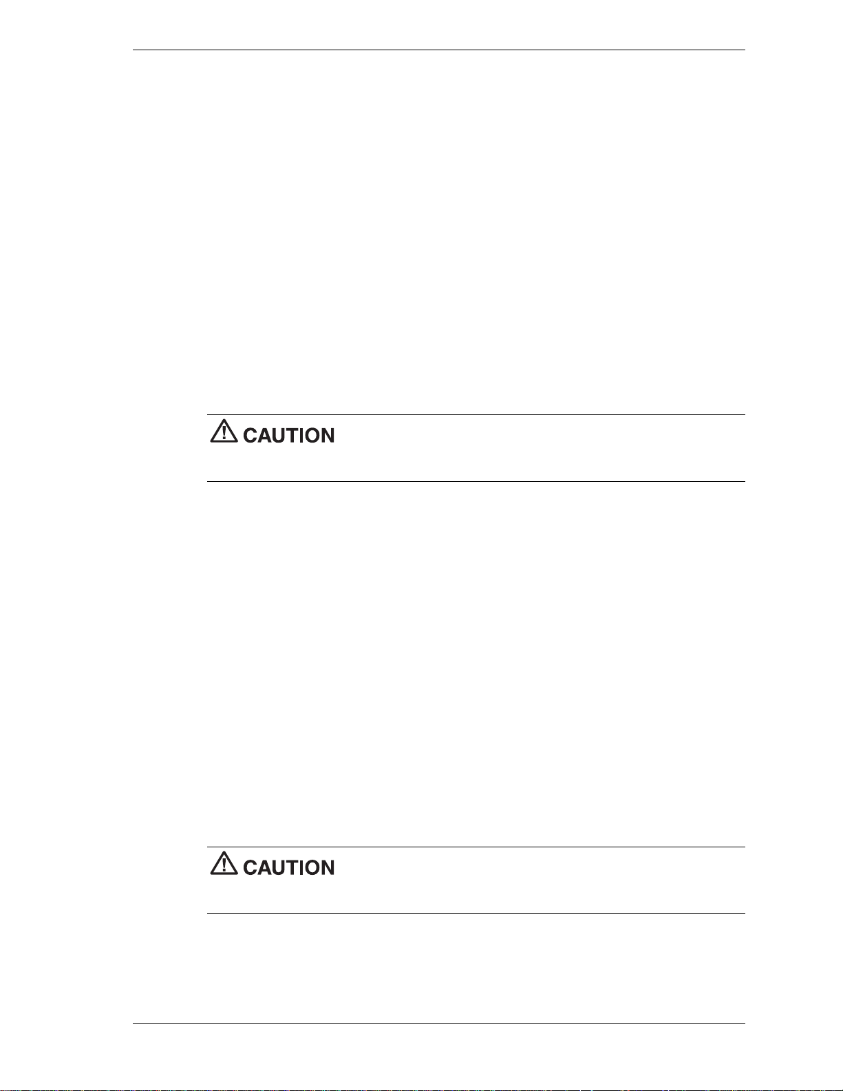
Using the Recovery Program
The Recovery Program main menu offers the following options:
Standard System Restore – select this option to restore your system to its original factory
!
software and settings.
Advanced Options – select this option to only install the Microsoft Windows operating
!
system.
Tools – choose this option to access the MS-DOS® edit mode, a series of hard disk utilities,
!
and a Master CD check program.
Cancel to return to DOS – select this option to close the Recovery program and exit to
!
MS-DOS mode.
Standard System Restore
The Standard System Restore recovery option resets your system to the original factory settings.
All files that were on the hard drive when you purchased the system are re stored. All the files
you added or created yourself and all changes made to the original files are lost after the
recovery process. Your hard disk is exactly the same as when it left the factory.
Before you begin the restoration process, back up your data files (for
example, your document and art files) onto storage di sk s such as Zip dis ks or onto a network
drive.
1.
Start the Recovery program (see “Starting the Recovery Program” earlier in this document).
2.
At the Recovery Program main menu, choose Standard System Restore.
The first part of the restor ation process t akes about a half hour. Do not remove the Recovery
Boot diskette from the diskette drive. Do not shut down the system.
3.
At the message informing you that the restoration process is finished, remove the Recovery
Boot diskette and the Product Recovery CD from their drives. Press
system.
The system restarts and installs the Windows operating system. This procedure can take as
long as an hour to complete. During this time, the system reinstalls all the or iginal software
and hardware configurati on settings.
4.
When the installations are finished, perform the same procedures as when you turned on
your computer for the first time.
Advanced Options
The Advanced Options menu lets you choose to reinstall only the Windows operating system or
to make changes t o Windows Setup.
qualified technician. If you are not completely sure that you want to continue, choose the Cancel
option by pressing Esc or by pressing 3 on your numeric keypad.
Enter
to restart your
The Advanced Options are only for use by an advanced PC user or
System Configuration 2-27

Tools
Advanced Options are as follows:
Reinstall Windows Only
!
This process formats the hard drive and performs a new installation of the Windows
operating system with the minimum settings. All data, including your personal files, are
permanently deleted. Before you begin this process, back up your data files.
Windows Setup (Windows 98 only)
!
This process runs Microsoft Windows Setup which reinstalls your opera ting system.
The Tools menu includes a series of advanced tools to maintain the hard drive and to check the
Product Recovery CD for potential errors.
The Tools options are only for use by an advanced PC user or qualified
technician. If you are not completely sure that you want to continue, choose the Cancel option by
pressing
Esc
or by pressing 3 on your numeric keypad.
Tools include the following options:
Edit
!
Runs the Microsoft MS-DOS editor for writing, editing, and modifying MS-DOS program
files.
ScanDisk
!
Runs Microsoft ScanDisk. This program checks your har d drive and helps you fix common
file and disk errors.
FDisk
!
Runs the hard disk partition manager utility. Inappro priate use of FDisk can result in an
irreversible loss of all data on the hard drive.
Format Hard Drive
!
Performs a quick format of the computer's hard disk. Inappropriate use of the Format
command can result in an irreversible loss of all the data on the hard drive.
Master CD Check
!
Checks for errors on the Product Recovery CD. If the Master CD Check reports a Master
CD error, contact NECC Technical Support.
Using the Smart Restore Program
Some systems have access to a Smart Restore program. Smart Restore lets you select which
applications you wish to (re-)install or remove. When you select to install applicatio n s, Smart
Restore does not destroy data on your hard drive, other than replacing old copies of the
application. When you remove an application, Smart Restore removes all the files of the selected
application. Smart Restore also allows you to (r e-)in stall hardware settings.
How to Load Smart Restore
To load Smart Restore, click the Windows
If you have not already placed the Product Recovery CD into the CD-ROM drive, do so now.
After the application loads, Smart Restore displa ys the main menu with a Software tab, a
Hardware tab, and (in some systems) a Tools tab.
2-28 System Configuration
Start
button, select
Programs, Tools
, and
Restore
.

Software Restore or Removal
Select the Software tab on the main menu to restore or remove specific applications:
Click on one or more programs to select them. Smart Restore indicates a selected program
!
with a green check mark in front of it. Deselect a selected program by double clicking it.
Click on the
!
To remove a program, double click it. A red cross in front of the program indicates it has
!
been selected for removal. To deselect the program, click on it again.
Hardware Settings
Select the Hardware tab on the main menu to restore hardware settings:
Click on one or more devices to select them. Smart Restore indicates a selected device with
!
a green check mark in front of it. To deselect the device, click on it again.
Click on the
!
Restoration Process
Once you have selected the p rograms or hardware settings you want to restore, click OK to start
the restoration process.
Each application or device you selected runs through its installation procedure. Continue as with
a normal installation, selecting the options you want. Each time the application asks you if you
wish to restart your system, select
installation.
When all the selected programs or devices are installed, remove the Product Recovery CD and
store it in a safe place.
Select All
Select All
button if you want to select all of the listed programs.
button if you want to select all of the listed devices.
Yes
to ensure all registry information is correct for the next
PowerMate Driver CD
The PowerMate Driver CD provides drivers for peripheral equipment that is available for
purchase to use with your PowerMate system. The equipment and the drivers are fully tested by
NECC to ensure their compatibility with the Po werMate system. If you need drivers for
peripheral devices you are adding to your system, use this CD.
The PowerMate Driver CD is easy to use. Start the system, and then insert the PowerMate
Driver CD. Follow the on-screen prompts to install the required drivers.
Intel Processor Serial Number Control Utility
The Intel Processor Serial Number Control Utility is a Windows program that enables or
disables the reading of the Pentium III processor serial number by software. This function lets
you control which software programs or websites have p ermission to read the processor serial
number. When installed, the utility runs automatically each time the system powers on.
Note
the Intel Pentium III processor. Installing this utility on a system that does not contain a
Pentium III processor generates an error message.
This utility places an icon in the Windows system tray. The icon provides a vi sual status of the
processor serial number. You have the option of hiding the system tray icon. You can enable or
disable the processor serial number at any time. However, enabling the serial number requires
restarting the system.
The Intel Processor Serial Number Control Utility is for use with systems shipping with
System Configuration 2-29

The following information describes:
system requirements
!
installation procedures
!
processor serial number features
!
Frequently Aske d Q uest io ns
!
technical support.
!
System Requirements
The Intel Processor Serial Number Control Utility requires:
a Pentium III processor-based system
!
Windows 98, Windows 2000, or Windows NT 4.0 (or later)
!
2 megabytes of hard drive space.
!
Installation
The Intel Processor Serial Number Control Utility (version 1.0) comes already installed on the
system. The system ships with the processor serial number feature turned off.
Processor Serial Number
The Intel processor serial number, a feature of the Pentium III processor, is an identifier for the
processor. The processor serial number is unique, and when used in conjunction with other
identification methods, can be used to identify the system or user. This number can be used in a
wide variety of applications that benefit from stronger forms of system and user identification.
The processor serial number is analogous to a conventional serial number, with these important
differences:
A software application can read the processor serial number.
!
You can enable or disable the reading of the serial number via utility programs such as this
!
one, or via the BIOS, de pending on the system configuration.
For additional information about the Pentium III pr ocessor and the processor serial number, visit
www.intel.com/pentiumiii.
Frequently Asked Questions
What are the benefits of the processor serial number?
You can use the processor serial number in applications that benefit from stronger forms of
system and user identification.
Why would I want to turn off my processor serial number?
Intel believes the processor serial number can provide compelling benefits to users. They are
developing features in conjunction with the processor serial number to allow responsible service
providers to provide services that maintain your privacy. However, if you are concerned that a
given application/servic e using your processor number might impact your privacy, you can turn
off the processor serial number using the utility.
2-30 System Configuration

What is the default state of the processor serial number?
The default state of the processor serial number is on, until the Processor Serial Number Control
Utility is installed. Once the Processor Serial Number Control Utility is installed, it turns the
processor serial number off by default. You can use the utility to turn on the processor serial
number.
Can a website read my serial number without my knowledge?
No, generally not. Websites cannot read serial numbers unless you allow them to download a
program that can read the processor serial number. Almost all browsers are configured to warn
users whenever they download executable software. Unless you disable the warning in the
browser, you should receive a notification.
Does Intel track serial numbers?
Generally not, other than related to the manufacturing process. Intel does not, in the absences of
advance and express consent of a user, collect serial number data that is otherwise identified
with a user.
Which programs and/or websites currently use the processor serial number?
You can find a complete list of programs that can take advantage of the processor serial number
and other new capabilities of the Pentium III processor at
ttp://www.intel.com/pentiumiii/utility.htm
.
How can I tell if my processor serial number is turned on?
The vast majori ty of Pentium III processor-based systems ship with the processor serial number
enabled. The control utility allows you to check the status by:
Viewing the icon itself. The disabled icon shows a red circle with a white “x.”
!
Clicking the task tray icon and selecting the “Status” menu item. Or you can select the
!
menu from the tool tip shown when you position the mouse over the task tray icon.
Intel Technical Support
For world wide 7 days a week, 24 hours a day technical support, please visit the Intel support
website at http://support.intel.com.
support@intel.com
Email:
In the United States, call
For world wide phone contacts, please see
.
800-628-8686
from 5:00 a.m. to 5:00 p.m. Pacific Standard Time.
http://support.intel.com/support/feedback.htm
.
System Configuration 2-31

Disassembly and Reassembly
!
System Covers
!
Expansion Boards
!
RIMM Memory Modules
!
Processor
!
5 1/4-Inch Accessible Drives
!
3 1/2-Inch Accessible Drives
!
3 1/2-Inch Internal Drives
!
CMOS Battery
!
System Board
3
!
Power Supply
!
Front USB Port
!
Front LED/Switch Bracket
!
Chassis Intrusion Switch
!
Minitower and Desktop Setup
!
Chassis Shell

This section contains step-by-step disassembly procedures for the PowerMate CT system. A
disassembly figure is provided with most procedures. For an illustrated parts breakdown and
parts list, see Section 5, “Illustrated Parts Breakdown.”
For complete disassembly of the system, follow the disassembly order listed in the follo wing
table. To reassemble, follow the table and procedures in reverse order. Where reassembly is not
apparent, reassembly procedures are provided.
A small flat head screwdriver, Phillips-head screwdriver, and needle nose pliers are the only
required tools.
PowerMate CT System Disassembly Sequence
Sequence Part Name See Page
1 System covers 3-3
2 Expansion boards 3-6
3 RIMM memory modules 3-12
4 Processor 3-16
6 5 1/4-inch accessible devices 3-18
7 3 1/2-inch accessible devices 3-24
8 3 1/2-inch internal drives 3-26
9 CMOS battery 3-30
10
11 Power supply 3-33
12 Front USB port 3-34
13 Front LED/switch bracket 3-34
14 Chass is intru si on switch 3-36
15 Minitower and desktop setup 3-37
16 Chass is she ll 3-40
System board
3-31
When disassembling the system, follow these general rules.
Turn off the system and unplug the AC power cord.
!
Disconnect all peripherals before disassembling the system.
!
Before opening the syste m or handling boards or chi ps, touch the frame to discharge static.
!
Do not disassemble parts other than those specified in the procedure.
!
The system uses several types of screws. Be sure to note the type of screw being removed.
!
Use the same type when assembling the system.
Label any connector before disconnecting it. Note where the connector goes and in what
!
position it was installed.
Use care in disconnecting cables. To prevent cable breakage, pull only on the connector. Do
!
not pull on the cable.
When installing a cable, route the cable so it is not pinched by other components and is out
!
of the path of the cover.
3-2 Disassembly and Reassembly

On completion of any reassembly, perform a power-on test. If a fault occurs, verify that the
reassembly was performed correctly.
System Covers
The following sections describe how to remove and replace the following system unit covers:
system cover
!
front panel.
!
Removing the Cover
Before installing optional hardware inside your system, you must first remove the cover from
the system unit.
system power cable. Power is removed only when the power cable is unplugged.
1.
Turn off a nd unplug the system unit.
2.
Disconnect any external devices (such as a keyboard and monitor) from the front or rear of
the system unit.
Before removing the cover, turn off system power and unplug the
Electrostatic discharge can damage computer components. Discharge
static electricity by touching a metal object before removing the cover.
3.
If the system unit is in the upright (minitower) position, place it on its right side (the side
with four rubber feet).
4.
If you have a padlock in the locking tab on the rear of the chassis, remove it.
5.
Remove the two thumbscrews holding the cover to the rear of the chassis.
Locating the Cover Screws
A – Cover C – Locking Tab
B
– Cover Screws
6.
Grasp the handle on the cover and slide the cover towards the rear of the chassis about an
inch (see the following figure).
7.
Lift the cover off the system and set aside.
Disassembly and Reassembly 3-3

Replacing the Cover
Replace the cover as follows.
crimping, abrasion, or cutting while installing the cover. Check that the ribbon cables are folded
along their fold lines and out of the direct path of the cover.
Removing the Cover
Ensure that all cables inside the chassis are positioned to prevent
1.
Position the cover over the side of the chassis so that the back edge of the cover is about an
inch beyond the back edge of the chassis (see the following figure).
2.
Align the tabs and slots on the cover with those along the edges of the chassis.
3.
Align the locking tab slot at the bottom rear of the cover with the locking tab.
Replacing the Cover
A – Side Slots and Tabs C – Front Slots and Tabs
B – Locking Tab (hidden)
3-4 Disassembly and Reassembly

4.
Firmly press the cover against the chassis and slide the cover towards the front of the
chassis until it locks in place.
Note
tabs at the front of the cover are properly inserted into their slots in the chassis. Check that the
locking tab is inserted into its slot on the back edge of the chassis. Also check that the tabs are
not bent closed. If they are, open them slightly.
5.
6.
7.
8.
9.
If the cover does not slide all the way to the front of the chassis, check that the cover
Replace the two previously removed thumbscrews.
If you have a padlock for the locking tab on the rear edge of the chassis, install it.
If the system is set up for use as a minitower, place the system unit upright.
Reconnect all external peripherals.
Plug in the power cables.
Removing the Front Panel
Remove the front panel if you are installing an internal 3 1/2 -inch hard d rive or installing a
device in one of the accessible device bays.
Remove the front panel as follows.
1.
Remove the cover (see “Removing the Cover” earlier in this section).
2.
Position the system on its side on your work table, with the front panel over the edge of the
table.
3.
Working from inside the chassis, press up on the two front panel locking tabs to release
them from their slots on the edge of the chassis (see the following figure for tab locations).
4.
On the right side of the front panel, at the top corner, press in on the panel to release the top.
5.
Pull out the top of the front panel while pulling up on the panel to release it fro m the
chassis. Set the panel aside.
Removing the Front Panel
A – Chassis Slots B – Locking Tabs
6.
If you are removing or installing a device, see one of the following sections.
! “Replacing 5 1/4-Inch Accessible Devices”
! “Replacing 3 1/2-Inch Accessible Devices”
! “Replacing Internal Drives.”
Disassembly and Reassembly 3-5

Replacing the Front Panel
Replace the front panel as follows.
1.
Align the three tabs (B) on the inside edge of the front panel with their corresponding slots
A
) on the lower edge of the chassis (see the following figure).
(
2.
Insert the tabs into their slots and press the front panel up against the chassis until the front
panel locks in place.
3.
Replace the cover (see “Replacing the Cover” earlier in this section).
Replacing the Front Panel
A – Slots on Chassis (3) C – Front Panel
B – Tabs on Front Panel (3) D – Chassis Front
Expansion Boards
The following sections describe how to:
remove and replace the retainer bar, which secures expansion boards and slot covers
!
remove and replace expansion boards
!
remove and replace slot covers.
!
The following figure shows the locations of the expansion slots on the chassis and the expansion
board connectors on the system board.
3-6 Disassembly and Reassembly

Locating Expansion Board Slots and Connectors
A
– PCI Expansion Board Connectors
B –
PCI Expansion Board Slots
Removing the Retainer Bar
Expansion boards and slot covers are held in place by a retainer bar. Remove the retainer bar
before removing or replacing expansion boards or slot covers.
Remove the retainer bar as follows.
1.
Remove the cover (see “Removing the Cover” earlier in this section).
2.
Press down on the two tabs on the retainer bar to release the tabs from their slots (see the
followin g fig ur e ) .
3.
Carefully remove the bar from the chassis.
Removing the Expansion Board Retainer Bar
C
– AGP Board Connector
D –
AMR Board Connector
A – Retainer Bar Tabs B – Tab Slots
4.
If you are removing an expansion board, see “Removing an Expansion Board.”
5.
If you are adding an expansion board, see “Replacing an Expansion Board.”
6.
To replace the retainer bar, see “Replacing the Retainer Bar” later in this section.
Disassembly and Reassembly 3-7

Removing an Expansion Board
Remove an expansion board as follows.
1.
Remove the cover (see “Removing the Cover” earlier in this section).
2.
Label and unplug any cables connected to the board.
3.
Remove the retainer bar (see “Removing the Retainer Bar”).
4.
Pull the board out of the connector and expansion slot. Set the board on an antistatic
surface.
If you are removing an AGP board, press out on the board’s locking lever while pulling the
board out of its connector.
Removing an Expansion Board
A
– Expansion Board
5.
Install a new board, or install the slot cover if you are not installi ng a board.
! If you are adding an expansion board, see “Installing an Expansion Board.”
! If you need to install a slot cover, see “Installing a Slot Cover.”
B
– AGP Video Board Locking Lever
3-8 Disassembly and Reassembly

Installing a Slot Cover
Install a slot cover as follows.
1.
Slide the slot cover into the expansion board slot (see the following figure).
Make sure the narrowed end of the slot cover goes into the metal strap. Its top edge should
fit around the raised hole in the edge of the chassis.
2.
Replace the expansion board retainer bar (see “Replacing the Retainer Bar” later in this
section).
3.
Replace the cover (see “Replacing the Cover” earlier in this section).
Installing a Slot Cover
Removing a Slot Cover
Remove a slot cover as follows.
1.
Slide the slot cover up to free it from the chassis (see the previous figure).
2.
Save the slot cover for future use.
3.
Install an expansion board (see “Installing an Expansion Board”).
4.
Secure the expansion board in place with the retainer bar (see “Replacing the Retainer
Bar”).
5.
Attach any signal cables required by the expansion board.
6.
Replace the cover (see “Replacing the Cover” earlier in this section).
A
– Slot Cover
Disassembly and Reassembly 3-9

Installing an Expansion Board
Install an expansion board as follows.
1.
Remove the cover (see “Removing the Cover” earlier in this section).
2.
Follow any preinstallation instructions that come with the expa nsion board (such as setting
jumpers on the board).
3.
Remove the retainer bar that secures the expansion boards (see “Removing the Retainer
Bar”).
4.
If you need to remove an old expansion b oard fro m t he connector designated for the new
board, see “Removing an Expansion Board.”
If a slot cover is in the slot, remove it (see “Removing a Slot Cover”). Save the slot cover
for future use.
5.
Hold the new expansion board by its edges or its bracket and insert it into the expansion
slot. If installing an AGP video board, lock the board in place with the locking lever (see the
followin g fig ur e ) .
Installing an Expansion Board
A
– Expansion Board
6.
Press the board firmly into the expansion slot connector on the system board.
7.
Secure the expansion board in place with the retainer bar (see “Replacing the Retainer
Bar”).
8.
Attach any signal cables required by the expansion board.
9.
Replace the cover (see “Replacing the Cover” earlier in this section).
3-10 Disassembly and Reassembly
B
– AGP Video Board Locking Lever

Replacing the Retainer Bar
Install the retainer bar as follows.
1.
Hold the retainer bar at an angle and insert the ends (A) into the slots (B) in the chassis (see
the following figure).
2.
Push the bar into the slots and under the edge of the chassis.
3.
Press down on the lock tabs (C) and firmly push the bar in until the tabs slide into their
D
slots (
4.
Replace the cover (see “Replacing the Cover”).
). Be sure that the raised portion on each tab locks into the slot (D).
Replacing the Retainer Bar
A
– Retainer Bar End
B – Retainer Bar Slot D – Lock Tab Slot
C
– Lock Tab
Disassembly and Reassembly 3-11

RIMM Memory Modules
See the following sections for procedures on removing or installing a RIMM memory module or
a continuity module. See Section 4, “System Boards,” for RIMM module upgrade paths and
guidelines for selecting RIMM modules.
Removing a RIMM or Continuity Module
Remove a RIMM module or a continuity module as follows.
Before opening the system and before handling boards or RIMM
memory modules, reduce static discharge by touching the chassis.
1.
Remove the cover (see “Removing the Cover” earlier in this section).
2.
Locate the RIMM memory sockets on the system board (see the following figure).
Locating the RIMM and Processor Sockets
A – Processor Socket C – RIMM 2 Socket
B – RIMM 1 Socket D – Wake-On LAN (WOL) Connector
3.
Eject a RIMM module or continuity module by pressing the plastic clips at the outer edges
of the socket away from the module (see the following figures).
For module identification, note that the RIMM module is taller than the continuity module
and has a cover over the memory on the module. Also note that the continuity module has
no memory installed on it.
If the system was just turned off, the RIMM module might be hot to the
touch. Use caution in removing the module to avoid a burn.
4.
Grasp the center of the module and pull it straight up and out of the socket. Store the
module in an anti-static bag.
5.
As required, install a replacement RIMM or continuity module (see “Installing a RIMM or
Continuity Module” in the next section).
3-12 Disassembly and Reassembly

Ensure that both RIMM sockets are filled with two RIMM modules or
one RIMM module and one continuity module. If both sockets are not filled, system memory won’t
work well or at all.
Removing a Continuity Module
A – Plastic Clip (2) B – Continuity Module
Removing a RIMM Module
A – Plastic Clip (2) B – RIMM Module
Disassembly and Reassembly 3-13
Installing a RIMM or Continuity Module
Install a RIMM module or a continuity module as follows.
1.
Remove the cover (see “Removing the Cover” earlier in this section).
2.
If you need to remove a currently installed RIMM or continuity module, see “Removing a
RIMM or Continuity Module” earlier in this section.
Before you install a module, reduce static disch arge by touchin g the
chassis.
3.
Grasp the new module in the middle and align the notches on the new module with the keys
in an empty RIMM socket (see the following figures).
4.
Press the module firmly into the socket.
5.
Make sure the locking clips at both ends of the module click closed.
Ensure that both RIMM sockets are filled with two RIMM modules or
one RIMM module and one continuity module. If both sockets are not filled, system memory won’t
work well or at all.
6.
Replace the cover (see “Replacing the Cover” earlier in this section).
Note
or in Windows with the amount of memory that you installed, check that you installed the memory
modules correctly.
If you find a discrepancy in the amount of memory displayed at the Power-On Self-Test
3-14 Disassembly and Reassembly

Installing a RIMM Module
A
– RIMM Module
B
– Notches
C
– Plastic Clip (2)
Installing a Continuity Module
A – Continuity Module C – Plastic Clip (2)
B – Notches
Disassembly and Reassembly 3-15

Processor
The system board has a Socket 370 for mounting a Celeron or Pentium III processor.
processor, system board, or both. Carefully follow the installation instructions provided with the
upgrade processor and the procedures in the following sections.
Ensure that you have the correct heat sink for the processor being installed. Do not use the heat
sink from the removed processor.
To remove the processor from the socket, see “Removing the Processor.” To install the upgrade
processor, see “Installing an Upgrade Processor.”
Removing the Processor
Remove the processor from its socket on the system board as follows.
chassis.
1.
Remove the cover (see “Removing the Cover” earlier in this section).
Incorrect installation of the processor and heat sink can damage the
Before handling components, reduce static discharge by touching the
2.
Locate the processor socket on the system board (see the figure “Locating the RIMM and
Processor Sockets” earlier in this section).
If the system was just running, the processor and heat sink on the
system board are hot. To avoid a burn, let the components cool before continuing.
3.
Tag and unplug the cooling fan cable from its connector (CPU Fan) on the system board.
4.
Remove the fan, heat sink, and retention clip from the processor as follows (see the
followin g fig ur e ) .
! Simultaneously press down on the flange on the end of the retention clip while
carefully pulling out the end to unhook it from the tab on the processor socket.
! Unhook the retention clip from the tab on the opposite side of the processor socket.
! Remove the fan, heat sink, and retention clip from the processor.
5.
Remove the processor as follows.
! Pull out on the processor socket lock lever just enough to release the lever from the
socket, then pivot the lever up to release the processor.
! Carefully lift up on the processor and remove it from the socket. Store the processor in
a static-free bag.
6.
Install the upgrade processor (see “Installing the Upgrade Processor” in the next section).
3-16 Disassembly and Reassembly

Removing the Fan, Heat Sink, and Processor
A
– Heat Sink
B
– Retention Clip
C
– Locking Lever
Installing an Upgrade Processor
Install the upgrade processor as follows.
1.
Remove the processor currently in the system (see “Removing the Processor” in the
previous section).
Before picking up the processor, reduce static disch arge by touchin g
the metal chassis.
2.
Align the triangle on the corner of the processor with the letters “CPU1” on the system
board.
3.
Carefully align the processor pins with the socket pin holes and set the processor into the
socket.
! If aligned correctly and the pins are not bent, the processor seats in the socket without
forcing.
! If the processor does not seat, check for correct alignment and bent pins.
D
– Processor
E
– Retention Clip Flange
4.
Pivot the lever down and press it in towards the socket until it lock s in place.
Using the wrong heat sink or no heat sink can damage the processor,
system board, or both. Ensure that the update processor has the correct heat sink (refer to the
documentation that comes with the kit).
Additional information can be obtained from NECC (see Section 8, “NEC Information Services”
for information on contacting NECC).
Disassembly and Reassembly 3-17

5.
Install a replacement heat sink and fan as follows and in accordance with the procedures
contained in the heat sink kit.
! If the kit includes a thermal pad, center it o n top of the processor.
! Align the heat sink and fan assembly with the processor and set it down on the
processor (see the previous figure for alignment).
! Attach the heat sink retention c l ip by hooking the non-flange end of t he clip over the
socket tab.
! Press the opposite end of the clip over the tab on the socket until it snaps in place.
6.
Plug the cooling fan cable into its connector (CPU Fan) on the system board.
7.
Replace the cover (see “Replacing the Cover”).
8.
Connect any peripherals and power cords, and power up the system.
5 1/4-Inch Accessible Devices
The chassis is designed so devices within it are easy to install and remove. Note these guidelines
before installing or removing a 5 1/4-inch device.
Special rails are used on 5 1/4-inch devices that allow them to be easily inserted and
!
removed.
The rails are designed to be stored in an empty bay when they are not attached to a device.
!
The bay cover cannot be secured over an empty bay if the bay has no rails.
Always place a bay cover over an empty bay.
!
NECC recommends that you always keep the rails if you remove a device from the system.
!
Use your stored rails on a new device if it doesn’t have the correct type of rail.
!
When you convert the chassis to a desktop or a minitower, always move the stored rails for
!
the new position as well.
For procedures on removing or replacing rails, covers, or devices, see the following sections:
“Removing or Replacing a Bay Cover”
!
“Storing and Retrieving Unused Rails”
!
“Removing or Installing Device Rails”
!
“Removing a 5 1/4-Inch Accessible Device”
!
“Installing a 5 1/4-Inch Accessible Device.”
!
3-18 Disassembly and Reassembly

Removing or Replacing a Bay Cover
If the system has an empty 5 1/4-inch device bay, it is covered with a special bay cover. This
cover physically protects the inside of the chassis, and its metal shielding also offers EMF
protection.
See the following sections for information on removing or replacing a bay cover.
Removing a Bay Cover
Remove a bay cover as follows.
1.
Remove the system cover and front panel, if not already removed (see “System Covers”).
2.
Press the tabs on either side of the cover toward each other until they are released from their
slots. The tabs are at the end of the rails inside the chassis.
3.
Still holding the tabs, slowly slide the cover out along the rails. As so on as the cover is free
of the chassis, the cover and the rails disassemble.
Removing a 5 1/4-Inch Device Bay Cover
4.
Use these rails on the new 5 1/4-inch device if its rails are the wrong type (see “Removing
or Installing Device Rails”).
If the device already has the right type of rails, set aside the rails you just removed for
future use.
Note
the bay.
Always keep unused rails; the bay cover cannot be replaced if there are no rails within
Disassembly and Reassembly 3-19

Replacing a Bay Cover
Replace a bay cover on a bay as follows.
Note
bay cover cannot be secured over the bay if the rails are absent.
1.
Place unused rails back in the empty bay before attempting to replace a bay cover. The
If necessary, put the rails back in the bay. The cover cannot be secured if there are no rails
within the bay. (See the next section, “Storing and Retrieving Unused Rails.”)
2.
Position the cover so the arrows on either side point up for the chassis orientation you are
using.
3.
Line up the cover tabs with the slots on the rails. These slots are about 1/4 inch in from the
ends of the rails (see the following figure).
4.
Place each cover tab in its slot.
Replacing a Bay Cover
A
– Slot on Rail
B – Tab on Bay Cover
Note: Rails are shown partially out of the system in this figure to show in detail the tabs at the
end of each rail; make sure rails are fully inserted before attaching a bay cover.
Storing and Retrieving Unused Rails
The device rails on the 5 1/4-inch devices in the system are designed specially for the chassis. If
the system has an unused 5 1/4-inch bay, there should be rails stored within it. Use these rails on
new devices (if necessar y). If you re move an old device, remove the rails and store them. If
there is an empty 5 1/4-inch bay, store the rails in the chassis; otherwise set the rails aside for
future use.
To store a rail in an empty bay:
1.
Position the end of the rail in the guides within the bay. The underside of the rail should be
to the wall of the bay. The tab should be angled away from the center of the bay (see the
followin g fig ur e ) .
C
– Bay Cover
3-20 Disassembly and Reassembly

Storing an Unused Rail
A – Front of Chassis C – Tab at End of Rail
B – Device Rail
2.
Press the rail against the wall of the bay with your thumb and press the tab toward the center
of the bay with your forefinger.
3.
Still pressing the tab, slide the rail into the bay along the guides until i ts tab clicks in place.
4.
Place a bay cover over the empty bay (see “Replacing a Bay Cover”).
To retrieve a rail from an empty bay:
1.
Press the rail against the wall of the bay with your thumb while you press the tab toward the
center of the bay with your forefinger.
2.
When the tab releases, slide the rail out along the guide.
Removing or Installing Device Rails
The 5 1/4-inch bays are designed for use with devices that have tabbed rails. These rails allow a
device to be easily inserted and removed from the system. If you remove a device from the
system, always save the rails, right in the bay if it is empty, to use on a replacement device.
1.
Remove a rail by removing the two or three screws that secure it to the side of the device.
2.
Secure each rail to the new device with the screws (two or three to a side) from the old
device.
Locating the Screws for 5 1/4-Inch Device Rails
A – Screw or Locking Pin B – Device Rail
Disassembly and Reassembly 3-21

Removing a 5 1/4-Inch Accessible Device
1.
Remove the system unit cover and front panel (see “Removing the Cover” and “Removing
the Front Panel”).
Before removing the cover, turn off system power and unplug the
system power cable. Power is removed only when the power cable is unplugged.
2.
Tag and unplug the power and signal cables connected to the device.
3.
Press the tabs on either side of the device inward to unlatch the device from the chassis (see
the following figure).
4.
Slide the device out of the accessible device cage in the chassis.
Releasing a 5 1/4-Inch Device
5.
Remove the rails from the old device (see “Removing or Installing Device Rails”).
If the bay is to remain empty, see step 6 only. If you are installing a new device, skip to
step 7.
6.
If the bay is to remain empty:
! Store the rails in the empty bay (see “Storing and Retrieving Unused Rails”).
! Place the bay cover over the bay (see “Replacing a Bay Cover”).
! Replace the front panel (see “Replacing the Front Panel”).
! Replace the cover (see “Replacing the Cover”).
7.
If you are installing a new device in the bay:
! If necessary, place the rails on the new device (see “Removing or Installing Device
Rails”).
! Install the device (see “Installing a 5 1/4-Inch Accessible Device”).
3-22 Disassembly and Reassembly

Installing a 5 1/4-Inch Accessible Device
Note
Use the rails from the old device or the empty bay.
1.
Install rails on the new device before attempting to insert the new device in the system.
Remove the system unit cover and front panel (see “Removing the Cover” and “Removing
the Front Panel”).
Before removing the cover, turn off system power and unplug the
system power cable. Power is removed only when the power cable is unplugged.
2.
If you are installing the device in an unused bay, remove the bay cover (see “Removing a
Bay Cover”).
If the bay contains a device to be removed, remove the device (see “Removing a 5 1/4-Inch
Accessible Device”).
3.
If the new device does not already have rails on either side, use the rails from the empty bay
or from the old device (see “Removing or Installing Device Rails”).
4.
Position the new device so it is right-side up for the chassis o r ientation you plan to use (see
the following figure).
Orient the 5 1/4-inch accessible device correctly for the configuration
(desktop or minitower) you plan to use. Make sure the device is right-side up for that
configuration.
5.
Slide the device into the device cage in the chassis. The tab on the end of each rail should
click into place when the device is in place.
Inserting a 5 1/4-Inch Device for Use in a Minitower
6.
Reconnect the power and signal cables to the device.
7.
Replace the front panel (see “Replacing the Front Panel”).
8.
Replace the system unit cover (see “Replacing the Cover”).
Disassembly and Reassembly 3-23

3 1/2-Inch Accessible Devices
The 3 1/2-inch accessible devices in the system are housed in a two-device bracket. The bracket
installs in the lowest bay of the accessible device cage, much like a 5 1/4-inch accessible device.
This applies equally to the desktop or minitower configuration.
The following sections describe how to remove and install 3 1/2-inch accessible devices in the
system.
Removing a 3 1/2-Inch Accessible Device
To remove a 3 1/2-inch accessible device, first remove the bracket holding the device from the
system, then remove the 3 1/2-inch accessible device from the bracket.
1.
Remove the system unit cover and front panel (see “Removing the Cover” and “Removing
the Front Panel”).
Before removing the cover, turn off system power and unplug the
system power cable. Power is removed only when the power cable is unplugged.
2.
Tag and unplug the power and signal cables connected to all devices in the two-device
bracket.
3.
Press the tabs on either side of the bracket inward to unlatch it from the chassis.
4.
Pull the bracket out the front of the chassis.
Removing the 3 1/2-Inch Accessible Device Bracket
5.
Unlatch the bracket cover by pressing the two side tabs towards each other (see the
following figure). Reach in behind the front shield of the bracket for access. Set the cover
aside.
6.
Remove the four screws (two to a side) that secure the device to the bracket (see the
followin g fig ur e ) .
3-24 Disassembly and Reassembly

The 3 1/2-Inch Accessible Device Bracket
A – Side Tabs on Bracket Cover C – Best Approach for
B – Drive Screws (two of four)
7.
Slide the device out the front of the bracket.
8.
If you are installing another 3 1/2-inch accessible device, see “Installing a 3 1/2-Inch
Accessible Device.” If you are not installing a new device at this time, continue with step 9.
9.
Press the plastic bay cover over the opening in the bracket cover.
Unlatching Side Tabs
10.
Press the bracket cover over the front shield so the two side tabs click into place.
11.
Slide the bracket into the chassis. The tab at either side of the bracket should click into
place.
12.
If there is still a device in the other bay of the bracket, reconnect its power and signal
cables.
13.
Replace the front panel (see “Replacing the Front Panel”).
14.
Replace the system unit cover (see “Replacing the Cover”).
Installing a 3 1/2-Inch Accessible Device
Install a new device in the bracket, and then install the bracket in the system.
Before removing the cover, turn off system power and unplug the
system power cable. Power is removed only when the power cable is unplugged.
1.
Follow the procedures in steps 1 to 8 in the previous section, “Re moving a 3 1/2-Inch
Accessible Device,” to remove the two-device bracket and (if applicable) the old device
from the system.
2.
If you are installing the device in an empty bay, uncover the bay:
! remove the 3 1/2-inch plastic bay cover from the bracket cover by pressing its tabs
together while pushing it out of its opening
! remove the breakaway shield (if any) from the front shield by twisting it gently until it
comes off.
3.
Slide the new device into the front of the bracket, connector end first.
Disassembly and Reassembly 3-25
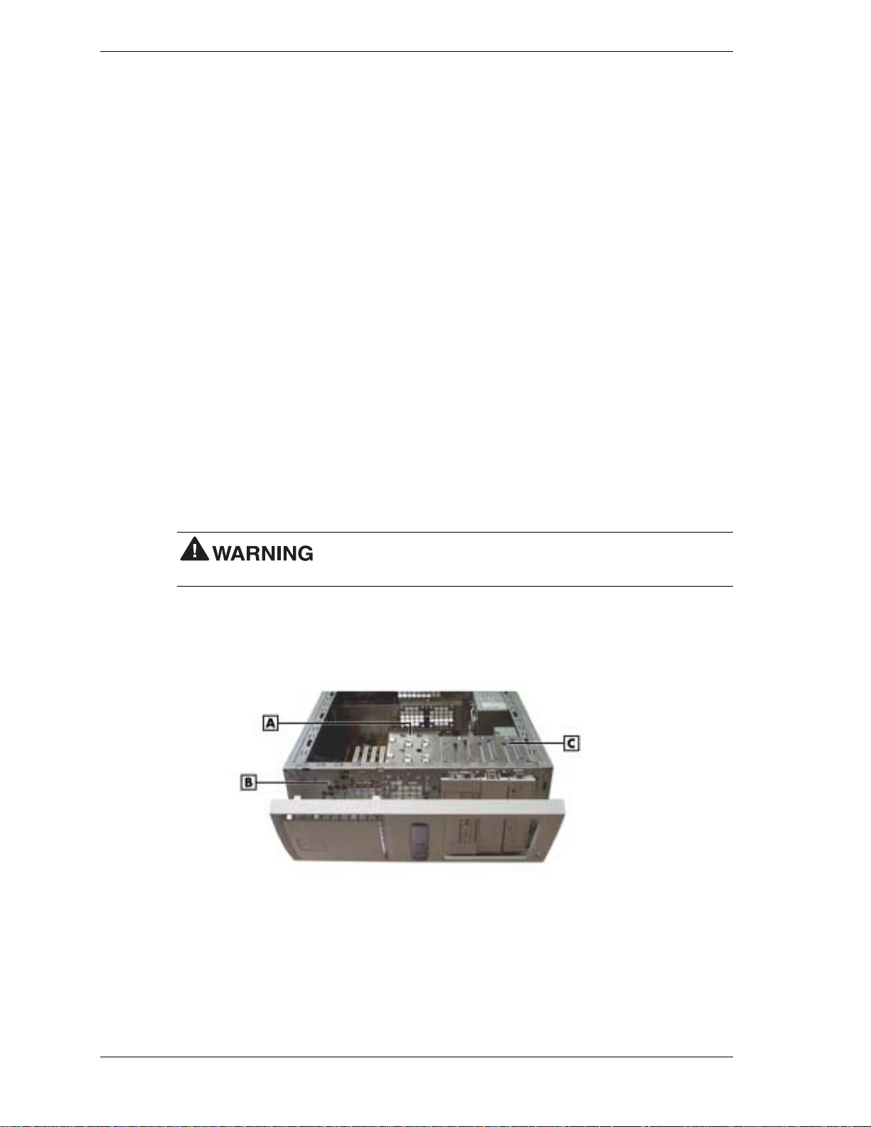
4.
Secure the new device to the bracket with four screws, two to a side (see the figure “The
3 1/2-inch accessible device bracket” in the previous section).
5.
Press the bracket cover over the front shield so the two side tabs click into place (see the
figure “The 3 1/2-inch accessible device bracket” in the previous section).
6.
Slide the bracket into the lowest accessible bay in the chassis (for the chassis orientation
you plan to use). The tab on the end of each rail should click into place when the bracket is
in place.
7.
Reconnect the power and signal cables for all devices in the two-device bracket.
8.
Replace the front panel (see “Replacing the Front Panel”).
9.
Replace the system unit cover (see “Replacing the Cover”).
3 1/2-Inch Internal Drives
The internal drives in the system are housed in a removable hard drive bracket. The hard drive
bracket is installed in the accessible device cage and is held in place by two screws on the front
of the chassis.
The following sections describe how to remove and insta ll 3 1/2-inch internal drives in the
system.
Removing a 3 1/2-Inch Internal Drive
1.
Remove the system unit cover and front panel (see “Removing the Cover” and “Removing
the Front Panel”).
Before removing the cover, turn off system power and unplug the
system power cable. Power is removed only when the power cable is unplugged.
2.
Locate the internal drive bracket in the system (see the following figure).
Locating the Internal Drive Bracket
A – Internal Drive Bracket C – Accessible Device Cage
B – Front of Chassis
3.
Tag and unplug the power and signal cables connected to all devices in the drive bracket.
4.
Remove the screws that hold the drive bracket to the front of the chassis (see the following
figure).
3-26 Disassembly and Reassembly

Locating Internal Drive Bracket Screws
A – Screws
5.
Slide the bracket back about one quarter inch. The tabs on the bracket should slide out of
the guides on the side of the accessible device cage (see the following figure).
Sliding the Internal Drive Bracket out of the Chassis
A – Guide B – Tab (one of four)
6.
Remove the four screws that secure the drive to the drive bracket (see the following figure).
Depending on the position of the drive, the screws might be located on opposite sides of the
bracket, or all on one side of the bracket.
Disassembly and Reassembly 3-27

Locating Internal Drive Screws on the Bracket
A – Screws (2 of 4) C – Screws (all on one side)
B – Screw Holes (2 of 4)
7.
Slide the device out the front of the bracket.
8.
If you are installing a new 3 1/2-inch internal drive, see “Installing a 3 1/2-Inch Internal
Drive.” If you are not installing a new drive, continue with step 9.
9.
Align the tabs on the bracket with the guides on the accessible device cage. Slide the
bracket into the chassis.
10.
Support the bracket within the chassis while you replace the screws at the front of the
chassis.
11.
Reconnect the power and signal cables of any drives still in the bracket.
12.
Replace the front panel (see “Replacing the Front Panel”).
13.
Replace the system unit cover (see “Replacing the Cover”).
Installing a 3 1/2-Inch Internal Drive
Before removing the cover, turn off system power and unplug the
system power cable. Power is removed only when the power cable is unplugged.
1.
Follow steps 1 to 8 of “Removing a 3 1/2-Inch Internal Drive” to remove the internal drive
bracket and (if applicable) an existing drive from the system.
2.
With the drive connectors last, slide the new drive into the bracket.
3.
Secure the new device in the bracket with four screws. Depending on the position of the
drive, the screws might be located on opposite sides of the bracket, or all on one side of the
bracket (see the previous figure).
4.
With the drive connectors last, slide the bracket into the chassis. The bracket should slide
along the guides on the side of the accessible device cage.
3-28 Disassembly and Reassembly

Locating Guides for the Internal Drive Bracket
5.
Support the bracket within the chassis while you replace the screws at the front of the
chassis.
Securing the Internal Drive Bracket
A – Screws
6.
Reconnect the power and signal cables for all devices in the drive bracket.
7.
Replace the front panel (see “Replacing the Front Panel”).
8.
Replace the system unit cover (see “Replacing the Cover”).
Disassembly and Reassembly 3-29

CMOS Battery
The system board uses a CMOS battery to maintain system configuration information. The
battery is a coin-cell battery mounted on the system board (see the following figure). I f it fails to
maintain system configuration information, replace it with an identically rated battery from the
same manufacturer.
discarded. Use only the same type battery or an equivalent type recommended by the
manufacturer when replacing the battery.
Lithium acts as a catalyst when exposed to water and causes spontaneous combustion on
contact. Discard used batteries according to the manufacturer’s instructions.
system configuration information. Prior to removing the battery, run the BIOS Setup Utility (see
Section 2) and print out or write down your system configuration settings. Then you can restore
the system to its previous settings.
If you need to replace the battery, follow these steps.
1.
Turn off and unplug the system and any external components connected to it.
The battery can explode if it is incorrectly replaced or improperly
Removing the battery from the system board causes the system to lose
2.
Remove the system cover (see “Removing the Cover” in Section 3). Observe all safety
precautions when removing the cover.
3.
Locate the battery on the system board (see the following figure).
Locating the Battery on the System Board
A – Battery
4.
Press down on the battery clip to release the battery from its socket on the system board.
5.
Remove the battery and discard in accordance with the manufacturer’s instructions.
3-30 Disassembly and Reassembly

Removing the Battery
A – Battery B – Clip
6.
With the positive (+) side of the new battery facing up, press the battery into the socket.
7.
Replace the system cover (see “Replacing the Cover”).
8.
Connect external peripherals and power cables, and power up the system.
9.
Run the Setup Utility to reconfigure your system parameters (see “BIOS Setup Utility” in
Section 2).
System Board
Remove the system board only if you cannot easily upgrade components on the system board
while it is within the chassis, or if you are replacing the system board.
Removing the System Board
1.
Remove the cover (see “Removing the Cover” earlier in this chapter).
system power cable. Power is removed only when the power cable is unplugged.
2.
Remove all installed expansion boards (see “Removing an Expansion Board”).
3.
Tag and disconnect all cables connected to the system board.
4.
Remove the six screws securing the system board in the chassis (see the following figure).
Before removing the cover, turn off system power and unplug the
Disassembly and Reassembly 3-31

Locating System Board Screws
A
– System Board Screws
5.
Ensuring you do not touch any components, caref ul ly lift the system board out of the
chassis.
6.
If you are discarding the board, first remove useable memory modules, the processor, or
cables, as appropriate.
7.
Set the system board aside on a stable static-free surface.
Reinstalling the System Board
NECC recommends that you contact your NECC Technical Support
Center for assistance in removing or replacing your system board.
1.
Place the system board in the chassis.
The screw holes in the board should align with the holes in the chassis. The back panel
connectors should fit perfectly into the back of the chassis.
2.
Secure the board to the chassis with the six screws previously removed.
3.
Reconnect any cables that were disconnected from the system board.
4.
Replace the expansion boards (see “Installing an Expansion Board”).
5.
If appropriate, install any memory modules, processor, or cables from a previous board.
6.
Replace the system unit cover (see “Replacing the Cover”).
3-32 Disassembly and Reassembly

Power Supply
Remove the power supply as follows.
system power cable. Power is removed only when the power cable is unplugged.
1.
Turn off the system and any connected peripherals.
2.
Unplug the system AC power cord and any peripheral power cords.
3.
Disconnect any attached peripherals.
4.
Remove the system cover (see “Removing the Cover” earlier in this section).
5.
Tag and unplug the power cables from all installed devices.
6.
Remove the four screws holding the power supply to the rear of the chassis.
Before removing the system cover, turn off the power and unplug the
Locating the Power Supply Screws
A – Screws (4)
7.
Slide the power supply towards the front of the chassis enough to clear the chassis.
8.
Lift the power supply out of the chassis and set aside.
Disassembly and Reassembly 3-33
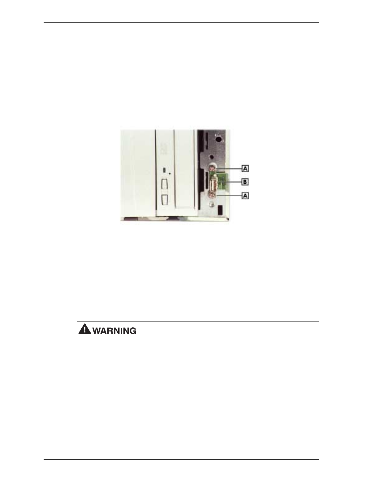
Front USB Port
Remove the front USB port using these steps.
1.
Remove the system unit cover and front panel (see “Removing the Cover” and “Removing
the Front Panel”).
2.
Disconnect the front USB port cable from its header on the system board.
3.
Remove the two screws that secure the USB port to the front of the c hass is. Save the
screws.
Locating Front USB Port Screws
A – Screw B – USB Port Board
4.
Gently pull the board off the chassis and feed its cable through the cutout in the front of the
chassis.
Reverse this procedure to install a front USB port.
Front LED/Switch Bracket
Remove the LED/switch bracket from the front of the chassis using these steps.
Before removing the system cover, turn off the power and unplug the
system power cable. Power is removed only when the power cable is unplugged.
1.
Remove the cover and front panel (see “Removing the Cover” and “Removing the Front
Panel”).
2.
Disconnect the LED/switch cable connector from its header on the system board.
3.
Press both sides of the LED/switch bracket together to d isengage the tabs that hold it to the
chassis. (The tabs are hooked on the left side, so only the tabs on the right side disengage.)
3-34 Disassembly and Reassembly

Releasing the Front LED/Switch Bracket
A – Front LED/Switch Bracket
4.
Open the LED/switch bracket toward the left. Once the right tabs are free, the hooked left
tabs can be freed.
Removing the Front LED/Switch Bracket
5.
Gently feed the LED/switch cable assembly through the cutout in the front of the chassis.
To replace the LED/switch bracket, reverse these steps.
Disassembly and Reassembly 3-35
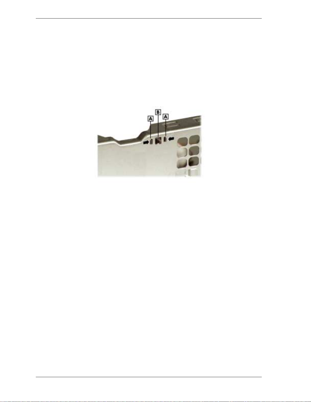
Chassis Intrusion Switch
If installed, remove the chassis intrusion switch from the rear edge of the chassis using these
steps.
1.
Remove the cover (see “Removing the Cover”).
2.
Disconnect the chassis intrusion switch cable from its header on the system board.
3.
Press together the tabs that hold the chassis intrusio n switch to the chassis (see the
followin g fig ur e ) .
Removing the Chassis Intrusion Switch
A – Tab C – Back of Chassis
B
– Chassis Intrusion Switch
4.
Once the tabs are free, gently push the chassis intrusion switch through its cuto ut in the
chassis wall.
To replace the chassis intrusion switch, reverse these steps.
3-36 Disassembly and Reassembly

Minitower and Desktop Setup
The system ships as a minitower and can be reconfigured as a desktop or, if a desktop, it can be
reconfigured back to a minitower. The accessible devices in the system can be positioned so
they are upright for the minitower orientation or for the desktop o r ientation.
The following sections describe how to convert between minitower and desktop orientations.
Converting from Minitower to Desktop
The system comes factory-shipped as a minitower computer. Convert the system for use as a
desktop computer using the following steps.
Before converting the system, turn off system power and unplug the
system power cable. Power is removed only when the power cable is unplugged.
1.
Turn off a nd unplug the system.
2.
Disconnect any external options (such as a keyboard and monitor) from the front or rear of
the system unit.
3.
Place the system unit on its right side. The lamps on the control panel should be below the
power button. The drives are now on their sides in the drive cage.
4.
Remove the system cover (see “Removing the Cover”).
5.
Remove the front panel (see “Removing the Front Panel”).
6.
Remove all devices, covers, and stored rails from the accessible device cage. See the
following sections for the procedures.
! “Re moving a Bay Co ver”
! “Storing and Retrieving Unused Rails”
! “Removing a 5 1/4-Inch Accessible Device”
! “Removing a 3 1/2-Inch Accessible Device”
7.
Replace all devices, covers, and rails in the accessible device cage so they are right-side up
in the drive cage. Place them in the same order they were in before. See the following
sections for the procedures.
! “Storing and Retrieving Unused Rails”
! “Replacing a Bay Cover”
! “Installing a 5 1/4-Inch Accessible Device”
! “Installing a 3 1/2-Inch Accessible Device”
Disassembly and Reassembly 3-37

Accessible Device Placement for a Desktop
A
– 5 1/4-Inch Bays on Top
8.
Remove the logo plate by unclipping its tabs from inside the front panel. Position the logo
plate so it is readable when the chassis is in the horizontal position. Press the tabs into the
front panel until they click in place.
9.
Replace the front panel (see “Replacing the Front Panel”).
10.
Replace the system cover (see “Replacing the Cover”).
Converting from Desktop to Minitower
If the system has been used as a desktop, you can convert it to a minitower system using the
following steps.
Before converting the system, turn off system power and unplug the
system power cable. Power is removed only when the power cable is unplugged.
1.
Turn off a nd unplug the system.
2.
Disconnect any external options (such as a keyboard and monitor) from the front or rear of
the system.
3.
Remove the system cover (see “Removing the Cover”).
B
– 3 1/2-Inch Bracket in Lowest Bay
4.
Remove the front panel (see “Removing the Front Panel”).
5.
Remove all devices, covers, and stored rails from the accessible device cage. See the
following sections for the procedures.
! “Re moving a Bay Co ver”
! “Storing and Retrieving Unused Rails”
! “Removing a 5 1/4-Inch Accessible Device”
! “Removing a 3 1/2-Inch Accessible Device”
3-38 Disassembly and Reassembly

6.
Replace all devices, covers, and rails in the accessible device cage so they sit sideways in
the drive cage, with their top surfaces toward the right end of the chassis (see the following
figure). Place them in the same order they were in before. See the following sections for the
procedures.
! “Storing and Retrieving Unused Rails”
! “Replacing a Bay Cover”
! “Installing a 5 1/4-Inch Accessible Device”
! “Installing a 3 1/2-Inch Accessible Device”
Accessible Device Placement for a Minitower
A
– 3 1/2-Inch Bracket
7.
Remove the logo plate by unclipping its tabs from inside the fron t p a nel. P osition the logo
B
– 5 1/4-Inch Bays
plate so it is readable when the chassis is in the vertical position. Press the tabs into the front
panel until they click in place.
8.
Replace the front panel (see “Replacing the Front Panel”).
9.
Replace the system cover (see “Replacing the Cover”).
10.
Place the system unit in a vertical position. The power button and the lamps on the control
panel should run from left to right. The drives should be right-side up i n the drive ca ge.
11.
Reconnect any external options (such as a keyboard and monitor) to the front or rear of the
system unit.
12.
Reconnect the power cable to the system and to a properly grounded wall unit or surge
protector.
Disassembly and Reassembly 3-39

Chassis Shell
Note
removed by authorized service personnel. No replaceable parts are accessed from this panel,
and it should only be removed if it is being replaced due to damage.
The chassis shell is secured to the chassis with two screws on the rear face of the chassis, and
three screws on the front face of the chassis. Remove all five screws. Carefully slip the shell,
which is slightly flexible, off the corners of the chassis. Lift the c hass is out of the shell.
The chassis shell (the U-shaped covering with rubber feet on two sides) should only be
Replacing the Chassis Shell
The chassis shell is secured to the chassis with two screws on the rear face of the chassis and
three screws on the front face of the chassis. To replace the chassis shell, orient it so its screw
holes align with the screw holes on the front and rear faces of the chassis. Place the chassis in
the chassis shell, and fit the corner edges of the shell over the chassis. Secure the shell to the
chassis with the five screws.
3-40 Disassembly and Reassembly

System Board
!
External Cable Connectors
!
Internal Cable Connectors
!
Jumper Settings
!
Upgrade Sockets
!
Components
!
Resources
4

This section describes the locations of connectors, jumpers, and sockets on the system board,
including any external cable connectors, internal board connectors and slots, jumper locations,
and upgrade sockets.
Included in this section are procedures for setting jumpers on the system board and a RIMM
memory upgrade path for the RIMM sockets. Also included are descriptions of system board
components, system memory map, I/O addresses, and DMA settings.
External Cable Connectors
Locations of the external cable connectors on the system board at the back of the minitower and
desktop systems are shown in the following figures. For descriptions of the connectors, see
Section 1, “System Overview.”
Minitower External Cable Connector Locations
4-2 System Board
A
– Keyboard Connector
B – Mouse Connector H – Line Out
C – Parallel Port I – Serial Port 2
D – MIDI/Game Port J – Serial Port 1
E – VGA Connector (on video board) K – USB Port
F – Microphone In
G
– Line In
 Loading...