


 Loading...
DLP Cinema® Projector
NC2000C
User’s Manual

Important Information
Precautions:
Please read this manual carefully before using your NC2000C and keep the manual handy for future reference.
Important Safeguards
These safety instructions are to ensure the long life of your projector and to prevent fire and shock. Please read them carefully and heed all warnings.
 WARNING
TO PREVENT FIRE OR SHOCK HAZARDS, DO NOT
EXPOSE THIS UNIT TO RAIN OR MOISTURE.
 CAUTION
TO REDUCE THE RISK OF ELECTRIC SHOCK, DO
NOT OPEN COVER. NO USER-SERVICEABLE PARTS
INSIDE. REFER SERVICING TO QUALIFIED SERVICE PERSONNEL.
This symbol warns the user that uninsulated voltage within the unit may have sufficient magnitude to cause electric shock. Therefore, it is dangerous to make any kind of contact with any part inside of this unit.
This symbol alerts the user that important literature concerning the operation and maintenance of this unit has been included.
Therefore, it should be read carefully in order to avoid any problems.
CAUTION
•In order to reduce any interference with radio and television reception use a signal cable with ferrite core attached. Use of signal cables without a ferrite core attached may cause interference with radio and television reception.
•This equipment has been tested and found to comply with the limits for a Class A digital device, pursuant to Part 15 of the
FCC Rules. These limits are designed to provide reasonable protection against harmful interference when the equipment is operated in a commercial environment. This equipment generates, uses, and can radiate radio frequency energy and, if not installed and used in accordance with the instruction manual, may cause harmful interference to radio communications. Operation of this equipment in a residential area is likely to cause harmful interference in which case the user will be required to correct the interference at his or her own expense.
WARNING
This is a Class A product. In a domestic environment this product may cause radio interference in which case the user may be required to take adequate measures.
DOC compliance Notice
This Class A digital apparatus meets all requirements of the
Canadian Interference-Causing Equipment Regulations.
Machine Noise Information Regulation - 3. GPSGV,
The highest sound pressure level is less than 70 dB (A) in accordance with EN ISO 7779.
Disposing of your used product
EU-wide legislation as implemented in each Member State requires that used electrical and electronic products carrying the mark (left) must be disposed of separately from normal household waste.
This includes projectors and their electrical accessories or lamps. When you dispose of such products, please follow the guidance of your local authority and/or ask the shop where you purchased the product.
After collecting the used products, they are reused and recycled in a proper way. This effort will help us reduce the wastes as well as the negative impact to the human health and the environment at the minimum level.
The mark on the electrical and electronic products only applies to the current European Union Member
States.
 WARNING
Installation and transport
Consult your dealer for installing and transporting the projector.
DO NOT install or transport the projector by non-professional person. Doing so may cause the lamp to break or may cause personal injury.
•Power Supply
-Consult your dealer for installing the power cable to the projector. DO NOT install the power cable by yourself.
Doing so may cause a fire or electric shock.
-The projector is so designed that it operates with the power supply voltage described below.
For C1 connection
(When the AC power to the projector power supply and
the lamp power supply is provided by a single cable)
•AC 200V-240V single phase 50/60Hz For C2 connection
(When the AC power to the projector power supply and the lamp power supply is provided by separate cables)
•AC 100V-240V single phase 50/60Hz (projector power supply)
•AC 200V-240V single phase 50/60Hz (lamp power supply)
Ensure that your power supply fits this requirement before attempting to use your projector.
-Handle the power cable carefully. A damaged or frayed power cable can cause electric shock or fire.
•Do not bend or tug the power cable excessively.
•Do not place the power cable under the projector, or any heavy object.
•Do not cover the power cable with other soft materials such as rugs.
•Do not heat the power cable.
•Turn off the projector, shut down AC power by using a circuit breaker and contact qualified service personnel under the following conditions. For C2 connection, turn off the projector, shut down the AC power to the projector and the lamp using a circuit breaker, and contact your dealer/distributor for a repair.
2

Important Information
-When the power cable is damaged or frayed.
-If liquid has been spilled into the projector, or if it has been exposed to rain or water.
-If the projector does not operate normally when you follow the instructions described in this user’s manual.
-If the projector has been dropped or the cabinet has been damaged.
-If the projector exhibits a distinct change in performance, indicating a need for service.
•Do not place the projector in the following conditions:
-near water, baths or damp rooms.
-on an unstable cart, stand, or table.
-in direct sunlight, near heaters or heat radiating appliances.
-in a dusty, smoky or steamy environment.
-on a sheet of paper or cloth, rugs or carpets.
•Do not place any liquids on top of your projector.
Refer servicing to qualified service personnel if liquid has been spilled.
•Prevent foreign objects such as paper clips and bits of paper from falling into your projector. Do not attempt to retrieve any objects that might fall into your projector. Do not insert any metal objects such as a wire or screwdriver into your projector. If something should fall into your projector, disconnect it immediately and have the object removed by a qualified service personnel.
For C2 connection, turn off the projector, shut down the AC power to the projector and the lamp using a circuit breaker, and contact your dealer/distributor.
•Do not cover the lens with the supplied lens cap or equivalent while the projector is on. Doing so can lead distorting or to melting of the cap and burning your hands due to the heat emitted from the light output.
 CAUTION
•High Pressure Lamp May Explode if Improperly Handled.
Only service personnel should open the lamp door. Refer Servicing to Qualified Service Personnel.
•Do not look into the lens while the projector is on. Serious damage to your eyes could result.
•Do not touch the projector during a thunder storm. Doing so can cause electrical shock or fire.
•Ensure that there is sufficient ventilation and that vents are unobstructed to prevent potentially dangerous concentrations of ozone and the build-up of heat inside your projector.
Allow at least 8 inches (20 cm) of space between your projector and a wall. Allow at least 20 inches (50 cm) of space between the ventilation outlet of the projector and an object.
Connect the projector exhaust outlet with the exhaust equipment having a capacity of 13 m3/min or more.
•Do not handle the projector and the power cable with wet hands. Doing so can cause electrical shock or fire.
•Shut down AC power to the projector and disconnect all the cables before moving the projector to another place. For C2 connection, turn off the projector, shut down the
AC power to the projector and the lamp using a circuit breaker. Disconnect the cables between devices and the lamp before moving the projector.
•Consult your dealer for installing the power cable to the projector. DO NOT install the power cable by yourself. Doing so may cause a fire or electric shock.
•To carry the projector, a minimum of five persons are required.
•Do not hold the lens part and the anamorphic lens part (or wide converter lens part) with your hand. Otherwise the projector may tumble or drop, causing personal injury.
•If the projector will not be used for an extended period of time, shut down AC power.
For C2 connection, turn off the projector, shut down the AC power to the projector and the lamp using a circuit breaker.
•Shut down AC power by using a circuit breaker before cleaning.
For C2 connection, turn off the projector, shut down the AC power to the projector and the lamp using a circuit breaker.
•Do not try to touch the ventilation outlet as it can become heated while the projector is turned on.
Doing so can lead to burning your hands due to the emitted heat.
•When main body is damaged, cooling fluids may come out of internal part. DO NOT touch and drink the cooling fluid.
When the cooling fluids are swallowed or contacted with your eyes, please consult with doctors immediately.
•When using a LAN cable:
For safety, do not connect to the connector for peripheral device wiring that might have excessive Voltage.
Installation
•Do not put the projector on its side when the lamp is on.
Doing so may cause damage to the projector.
•Handle your projector carefully. Dropping or jarring your projector could damage internal components.
•Controlled ambient light environments will allow for an image of higher contrast and depth to be displayed.
•Screens with a soiled, scratched, or discolored area will not produce a clean image. Care should be used in the handling of the screen.
•To carry the projector, a minimum of five persons are required.
Remove the lens and the lamp before carrying the projector.
Do not apply a strong shock to the projector.
•Keep finger prints or dust off the lens surface. Leaving finger prints or dust can cause unwanted shadows on the screen.
Cover the lens with the supplied lens cap if the projector is not to be used for an extended period of time.
Lamp Caution: Please read before operation
•Due to the lamp being sealed in a pressurized environment, there is a small risk of explosion, if not operated correctly. There is minimal risk involved, if the unit is in proper working order, but if damaged or operated beyond the recommended hours, the risk of explosion increases. Please note that there is a warning system built in, that displays following message when you reach a preset operating time “Bulb Over Time”.
When you see this message please contact your dealer for a replacement.
If the lamp does explode, smoke will be discharged from the vents located on the back of the unit. Do not stand in front of the vents during the operation. This smoke is comprised of glass in particulate form and Xenon gas, and will not cause harm if kept out of your eyes. If your eyes have been exposed to this gas, please flush your eyes out with water immediately and seek immediate medical attention. Do not rub your eyes! This could cause serious injury.
3

Important Information
•Consult qualified service personnel for cleaning the inside of the projector or lamp replacement. Do not try to clean the inside of the projector or replace the lamp by yourself.
•Do not shut down AC power to the projector under the following conditions. Doing so can damage the projector.
-While projecting images.
-While cooling after the projector has been turned off. (The POWER button LED blinks in white while the fan is rotating, and “Cooling...” is displayed on the LCD screen. The cooling fan continues to work for 5 minutes.)
For questions relating to unclear points or repairs
Contact your dealer or the following support branch for questions relating to unclear points, malfunctions and repairs of the product.
In Europe
NEC Europe, Ltd. / European Technical Centre
Address: Unit G, Stafford Park 12, Telford TF3 3BJ, U.K. Telephone: +44 1952 237000
Fax Line: +44 1952 237006
4

Table of Contents |
|
Table of Contents ............................................................................ |
5 |
1.What’s in the Box? and the Names of the Projector Parts............. |
6 |
1-1. Features .................................................................................................................................................................... |
6 |
1-2. What’s in the Box? ................................................................................................................................................... |
8 |
1-3. Names of the Projector Parts .................................................................................................................................. |
9 |
2.Installation and Connection ....................................................... |
16 |
2-1. Steps for setting up and connecting .................................................................................................................... |
16 |
2-2. Connecting the image input terminals ................................................................................................................. |
17 |
2-3. Connecting the various control terminal ............................................................................................................. |
18 |
3.Projection of Images (Basic Operation) ...................................... |
19 |
3-1. Steps of projecting images ................................................................................................................................... |
19 |
3-2. Turning your projector on ..................................................................................................................................... |
20 |
3-3. Selecting the title of input signal .......................................................................................................................... |
22 |
3-4. Adjusting the position and the size of projected screen .................................................................................... |
23 |
3-5. Preventing misoperations ..................................................................................................................................... |
27 |
3-6. Turning on/off the lamp with the projector turned on ......................................................................................... |
28 |
3-7. Turning your projector off ..................................................................................................................................... |
29 |
4.Using Menus .............................................................................. |
30 |
4-1. Basic operation with adjustment menus ............................................................................................................. |
30 |
4-2. Table of adjustment menus ................................................................................................................................... |
35 |
4-3. Title Select .............................................................................................................................................................. |
36 |
4-4. Configuration .......................................................................................................................................................... |
37 |
4-5. Title Setup ............................................................................................................................................................... |
38 |
4-6. Information .............................................................................................................................................................. |
38 |
5.Maintenance of Your Projector ................................................... |
42 |
5-1. Cleaning the Cabinet .............................................................................................................................................. |
42 |
5-2. Cleaning the Lens .................................................................................................................................................. |
42 |
5-3. Replacing the Air Filter .......................................................................................................................................... |
43 |
6.Appendix .................................................................................... |
50 |
6-1. Troubleshooting ..................................................................................................................................................... |
50 |
6-2. Indicator display list ............................................................................................................................................... |
52 |
6-3. Operation using an HTTP browser ....................................................................................................................... |
54 |
6-4. Outline Drawing ...................................................................................................................................................... |
56 |
6-5. Specifications ......................................................................................................................................................... |
57 |
6-6. Pin Assignment and Functions of Terminal ......................................................................................................... |
58 |
6-7. Related products list .............................................................................................................................................. |
66 |
5

1.
What’s in the Box? and the Names of the Projector Parts
1-1. Features
• DLP Cinema® dedicated projector that supports large screen needs
NEC has applied its mounting technology and leading imaging technology to newly develop lamp and optical systems as well
as a cooling system to support large screen needs.
• Equipped with easy to use functions
(1)Lens memory function that can be operated with one touch, and lamp power memory function
The DLP Cinema® projector is provided with a lens memory function for storing lens zoom positions and shift positions to set screens sizes for each input signal. It is also provided with a lamp power memory function for storing the brightness of the images on the screen for each input signal.
Even if you are projecting multiple images that have different settings for image sizes and brightness, you can project them with the conditions pre-registered for each signal, simply by selecting the corresponding signal.
(2)Equipped with a lamp output control function
You can set to any brightness setting, from low brightness to high brightness. This function makes it possible to minimize the fluctuation (*) in brightness as brightness of the lamp decreases as a result of long-term lamp usage.
* The time for maintaining fluctuations in brightness depends on the setting value for brightness.
(3)Easy lamp replacement
The lamp can be replaced from the backside of the projector, so the lamp can be easily replaced even in narrow locations when a film projector is setup on the side and there is not much space on the projector side.
(4)Registered signal selection buttons
The projector has been equipped with new 8 signal selection buttons that make it easy to select registered signals. To this projector, 100 titles at most can be registered (input signal registration). Among the registered titles, any 8 titles can be assigned to the buttons <1> to <8>.
(5)Software which enables the user to operate the projector from a PC via a network is available (optional).
You can operate the projector via a network by installing the separately supplied Digital Cinema Communicator (DCC) on your PC.
(6)Supports various contents and types of usage by applying a separately-sold multi-media switcher.
By connecting an optional multi-media switcher (MM3000B), you can input RGB/VIDEO analog signals, and digital signals in formats not supported by the projector.
6

1.What’s in the Box? and the Names of the Projector Parts
•DMD Face Dust Protection Structure
A dust control shield is arranged between each DMD chip of R, G and B, and the spectroscopic/condenser prism to prevent dust and dirt in the air, and oily particles in smoke associated with event halls from coming into contact with the face of the DMD and causing operating problems.
• Efficient cooling of the heat from the DMD unit by the cooling structure
The DMD unit uses a highly efficient liquid cooling method. This efficiently eliminates heat applied to the DMD by the complete dust control structure and high light output, thereby ensuring the reliability of the projector.
7

1. What’s in the Box? and the Names of the Projector Parts
1-2. What’s in the Box?
Check the content of the accessories.
NC2000C projector |
Small iris x 1 |
|
Cover key x 2 |
Attachment for lamp x 1
Lamp door key x 2
Exhaust outlet protective sheet x 1
Important Information x1
Exhaust outlet protective sheet fastening band x 4
CD-ROM (User’s Manual)
TIP * In the event that you did not receive all of the accessories outlined above, or some are damaged, contact your dealer/distributor.
Differs slightly from the drawings in this manual, but there is no problem in actual use.
8
1. What’s in the Box? and the Names of the Projector Parts
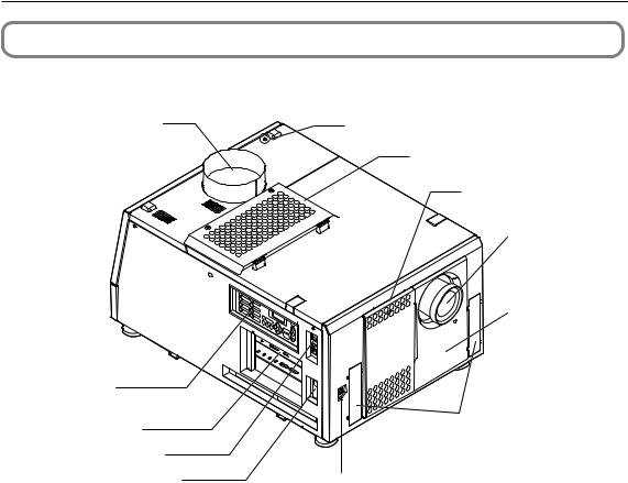
1-3. Names of the Projector Parts
1-3-1. Front of the Projector
1 |
6 |
7
|
|
|
8 |
|
|
|
9 |
1 |
|
|
|
2 |
5 |
|
|
3 |
6 |
LAMP |
10 |
4 |
8 |
||
|
7 |
|
|
IMB |
MENU |
K |
|
|
LOEYCK |
|
ENTER |
|
EXIT |
2
3 |
11 |
|
|
4 |
|
5 |
12 |
1. Air outlet (for cooling the lamp)
Connects to an exhaust device to exhaust heat from the lamp. Please contact your dealer/distributor to install the exhaust device.
2. Control panel
On the control panel, power to your projector is turned on or off, titles are selected, and various adjustments are made of projected screen. (See page 14)
3. Connection terminals
Various image signal cable are to be connected here. (See page 13)
You can expand signal input terminals by installing the optional media block (NC-80MB01) or internal multi-media switcher (MM3000B).
Contact your dealer/distributor for more information on the NC-80MB01 and MM3000B.
4. Projector power switch (upper), lamp power switch (lower)
The projector enters the standby state when you turn on the lamp power switch and projector power switch while the AC power is on.
5. Ethernet port
The connector for external devices such as a cinema server or a PC installed with the DCC. (See page 13)
6. Buzzer
The buzzer rings when the power is turned on or an error has occurred.
7. Air inlet (for cooling the lamp)
The air inlet for cooling the lamp. Do not cover.
An air filter is attached over the air inlet to prevent dust. Refer to “5-3. Replacing the Air Filter” (page 43) on how to replace the air filter.
8. Air inlet (for cooling the projector electric circuits)
The air inlet for cooling the projector electric circuits. Do not cover.
An air filter is attached over the air inlet to prevent dust. Refer to “5-3. Replacing the Air Filter” (page 43) on how to replace the air filter.
9

1. What’s in the Box? and the Names of the Projector Parts
9. Lens (optional)
Images are projected from the lens. Request your dealer/distributor to install or replace the lens.
10.Interlock connector (Inside front of projector)
This is the connector for the projector safety device. This is used to control the projector from an external source. Consult with your dealer/distributor about using this.
11. Conversion lens stay fittings
Fittings to attach the fixing stay when using the optional conversion lens (anamorphic lens or wide converter lens). Contact your dealer/distributor for more information on the conversion lens and fixing stay.
12.Conversion lens stage connecter terminal
The terminal to connect the control connector of the conversion lens table when using the optional conversion lens (anamorphic lens or wide converter lens). Contact your dealer/distributor for an installation of the conversion lens.
NOTE Do not touch the air outlet and backside of the main unit when your projector is operating. Otherwise, the high temperature may cause burns.
10
1. What’s in the Box? and the Names of the Projector Parts
1-3-2. Rear of the projector
1 |
6 |
7
2
8
9
3
4
6
5
1. Cooling fluid gauge
The gauge to indicate the remaining amount of the DLP cooling fluid.
2. Function expansion terminal connector
The connector to attach the terminal to expand the projector functions.
3. AC power cable
This is the cable that supplies AC power to the projector head. Contact your dealer/distributor for connecting the power cable or AC power cable.
4. Air inlet (for cooling the projector electric circuits)
The air inlet for cooling the projector electric circuits. Do not cover. An air filter is attached over the air inlet to prevent dust. Refer to "5-3. Replacing the Air Filter" (page 43) on how to replace the air filter.
5. Level adjusters (in four positions on bottom)
In the ordinary installation, you can adjust the projector inclination at 4 positions.
6. Air outlet (for cooling the projector electric circuits)
The air outlet to exhaust the heat from the projector electric circuits. Do not cover.
7. Rear status indicator
These indicate the status of the projector. When the projector is operating normally, these light/blink in green or orange. When an error occurs, they light/blink in red. When an error occurs, check the contents of the display on the LCD screen. (See page 53)
8. Lamp door
This opens to allow the lamp to be replaced. Please contact your dealer/distributor to install and to replace the lamp bulb and lamp house.
9. Optical axis adjustment system protection cover
The protection cover for the optical axis adjustment system (screw) for the lamp. Do not open this cover. Contact your dealer/distributor for adjusting the optical axis.
NOTE Do not cover the air inlets and outlet while the projector is in operation. Insufficient ventilation leads to a rise of the internal temperature and may cause a fire or malfunction.
11

1. What’s in the Box? and the Names of the Projector Parts
 WARNING:
Only service personnel should open the lamp door.
•The interior reaches high temperatures and there is a risk of burns.
•There is a risk of injury if the lamp is broken.
12
1. What’s in the Box? and the Names of the Projector Parts
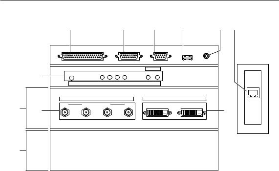
1-3-3. Connection terminals
1 |
2 |
3 |
4 |
5 |
6 |
7
10 8
|
GP I/O |
|
3D |
RS-232 |
REMOTE |
|
|
|
|
|
USB |
|
|
|
|
PORT |
|
|
PWR |
SOFT OS FMT ICP |
B A |
|
|
|
|
FOR SERVICE |
|
|
LAN |
|
|
|
|
|
|
NC-80LB01 |
|
|
|
|
|
|
|
SDI |
|
|
DVI |
A |
B |
C |
D |
A |
B |
9
11
1. External control terminal (GP I/O) (D-Sub 37P)
The terminal for externally controlling the projector or connecting a 3D image system to the projector. (See page 59)
2. 3D terminal (3D) (D-Sub 15P)
The terminal for connecting a 3D image system to the projector. (See page 64)
3. PC control terminal (RS-232C) (D-Sub 9P)
The terminal for service personnel to set data for the projector or for operating the projector from a PC via an RS-232C. Connect the projector and the PC with a commercially available RS-232C straight cable.
4. USB port (USB) (type A)
The port for the projector maintenance.
5. Remote control device terminal (REMOTE) (Stereo mini)
The terminal for controlling the projector from a remote control device.
6. Ethernet port (LAN) (RJ-45)
The port for interfacing with an image signal server or controlling the projector from a PC via a network. Connect the projector and the PC with a commercially available Ethernet cable (10/100/1000Base-T).
7. Device management indicator
The indicator for displaying the projector status. Used by service personnel during maintenance.
8. HDSDI input terminal (SDI-A/SDI-B/SDI-C/SDI-D) (BNC)
The terminal for connecting an image signal server or video imaging device. Use a 75Ω coaxial cable. Use a combination of SDI-A and SDI-B, or SDI-C and SDI-D for a dual-link connection.
9. DVI-D input terminal (DVI-A/DVI-B) (DVI-D 24P)
The terminal for connecting a DVI-D output terminal of a PC. Use a commercially available DVI-D signal cable (single-link).
10.Slot B
The slot for a signal input board (NC-80LB01) or media block (NC-80MB01).
A signal input board is installed at the time of factory shipping. Contact your dealer/distributor for an installation or uninstallation of a signal input board or media block.
11. Slot A
The slot for a media block (NC-80MB01) or internal multi-media switcher (MM3000B).
The slot is empty at the time of factory shipping. Contact your dealer/distributor for an installation of a media block or internal multi-media switcher.
13

1. What’s in the Box? and the Names of the Projector Parts
1-3-4. Control panel
1 |
2 |
3 |
4 |
5 |
6 |
1 5
26
37
48
KEY
LOCK
LAMP |
MENU |
ENTER |
DOUSER |
IMB |
|
EXIT |
|
7
8
9
10 |
11 |
12 |
13 |
14 |
1. Button <1> to <8>
Press the button <1> to <8> to select a title (input signal) assigned to each button.
Up to 100 titles (input signals) can be registered to this projector, and any 8 titles from them can be assigned to the button <1> to <8>.
Indicators on the left of each button show their assigned title or selection status.
Lit white |
A title is assigned to the button |
|
|
Lit green |
The title is being selected |
|
|
Off |
No title is assigned to the button |
|
|
2. LAMP button
Press this button to display the lamp adjustment menu. (See page 26)
3. MENU button
Press this button to display the menu for various settings and adjustments. (See page 35)
4. LCD screen
The LCD screen displays menus and setting values for the projector operations.
5. ENTER button
Press this button to select the menu item.
6. KEY LOCK button
Press this button to lock (KEY LOCK) the buttons on the control panel. Buttons on the control panel do not function while KEY LOCK is on.
Pressing the KEY LOCK button for one second or longer while KEY LOCK is off locks the buttons.
Pressing the KEY LOCK button for one second or longer while KEY LOCK is on unlocks the buttons. (See page 27)
NOTE KEY LOCK becomes automatically on if no control panel operation takes place in the standby state for 30 seconds by default. (See page 27)
14

1. What’s in the Box? and the Names of the Projector Parts
7. POWER button
Press this button for more than three seconds to turn on or off (standby) the projector.
Turn on the lamp power switch and projector power switch to set the projector in the standby state before turning on the projector. (See page 20)
Lit green |
Power is on |
|
|
Blinking green |
The projector is starting up. |
|
|
Lit white |
Power is off (in the standby state) |
|
|
Blinking white |
The cooling fan(s) is running immediately after a power-off. |
|
|
8. DOUSER button
Press this button to open and close the douser.
9. LAMP ON/OFF button
Press this button for five seconds or longer to turn on or off the lamp while the projector is on. (See page 28)
10.IMB button
This button is operable when the media block NC-80MB01 is installed in the projector. Press this button to display the operation menu of the media block.
11. Play/pause button
This button is operable when the media block NC-80MB01 is installed in the projector. Press this button to play or pause the image contents.
12.Stop button
This button is operable when the media block NC-80MB01 is installed in the projector. Press this button to stop playing the image contents.
13. / / / (UP/DOWN/LEFT/RIGHT) buttons
Press these buttons to select a menu item while a menu is displayed.
14.EXIT button
Press this button to return to the previous menu item.
15

2.
Installation and Connection
2-1. Steps for setting up and connecting
Use the following steps for setting up your projector:
• Step 1
Setup the screen and projector. (Contact your dealer to carry out the setup.)
• Step 2
Connect cables to the image input terminals. (See page 17)
Connect cables to the various control terminals. (See page 18)
16

2. Installation and Connection
2-2. Connecting the image input terminals
The projector has two image input terminals (HDSDI input terminal and DVI-D input terminal).
• |
HDSDI A/B/C/D input terminal ------------------------- |
Inputs serial digital images from a cinema server or an image device such |
||||||||||||
|
(SDI-A/SDI-B/SDI-C/SDI-D) |
as HDSDI or VTR. |
||||||||||||
• |
DVI-D A/B input terminal (DVI A/DVI B) ------------- |
Inputs digital RGB signals from a PC. |
||||||||||||
|
75Ω coaxial cable |
|
|
|
|
|
|
|
DVI-D signal cable |
|||||
|
|
|
|
|
|
|||||||||
|
|
|
|
|
|
|
|
|
|
|
|
|
|
|
|
|
|
|
|
|
|
|
|
|
|
|
|
|
|
|
|
|
|
|
|
|
|
|
|
|
|
|
|
|
|
|
|
|
|
|
|
|
|
|
|
|
|
|
|
|
|
|
|
|
|
|
|
|
|
|
|
|
|
|
|
|
|
|
|
|
|
|
|
|
|
|
|
|
|
|
|
|
|
|
|
|
|
|
|
|
|
|
|
|
|
|
|
|
|
|
|
|
|
|
|
|
|
|
|
|
|
|
|
|
|
|
|
|
|
|
|
|
|
|
|
|
|
|
|
|
|
|
|
|
|
|
|
|
|
NC-80LB01
|
|
|
|
|
|
|
|
|
|
|
|
SDI |
|
|
|
|
DVI |
|
|
|
|
|
|
|
|
|
A |
|
B |
C |
|
D |
|
A |
B |
|
|
|
|
|
|
|
|
|
|
|
|
|
|
|
|
|
|
|
|
|
|
|
|
|
|
|
|
|
|
|
|
|
|
|
|
|
|
|
|
|
|
|
|
|
|
|
|
|
|
|
|
|
|
|
|
|
|
|
|
|
|
|
|
|
|
|
|
|
|
|
|
|
|
|
|
|
|
|
|
|
|
|
|
|
|
|
|
|
|
|
|
|
|
|
|
|
|
|
|
|
|
|
|
|
|
|
|
|
|
|
|
|
|
|
|
|
|
|
|
|
|
|
|
|
|
|
|
|
|
|
|
|
|
|
|
|
|
|
|
|
|
|
|
|
|
|
|
|
|
|
|
|
|
|
|
|
|
|
|
|
|
|
|
|
|
|
|
|
|
|
|
|
|
|
|
|
|
|
|
|
|
|
|
|
|
|
|
|
|
|
|
|
|
|
|
|
|
|
|
|
|
|
|
|
|
|
|
|
|
|
|
|
|
|
|
|
|
|
|
|
|
|
|
|
|
|
|
|
|
|
|
|
|
|
|
|
|
|
|
|
|
|
|
|
|
|
|
|
|
|
|
|
|
|
|
|
|
|
|
|
|
|
|
|
|
|
|
|
|
|
|
|
|
|
|
|
|
|
|
|
|
|
|
|
|
|
|
|
|
|
|
|
|
|
|
|
|
|
|
|
|
|
|
|
|
|
|
|
|
|
|
|
|
|
|
|
|
|
|
|
|
|
|
|
|
|
|
|
|
|
|
|
|
|
|
|
|
|
|
|
|
|
|
|
|
|
|
|
|
|
|
|
|
|
|
|
|
|
|
|
|
|
|
|
|
|
|
|
|
|
|
|
|
|
|
|
|
|
|
|
|
|
|
|
|
|
|
|
|
|
|
|
|
|
|
|
|
|
|
|
|
|
|
|
|
|
|
|
|
|
|
|
|
|
|
|
|
|
|
|
|
|
|
|
|
|
|
|
|
|
|
|
|
|
|
|
|
|
|
|
|
|
|
|
|
|
|
|
|
|
|
|
|
|
|
|
|
|
|
|
|
|
|
|
|
|
|
|
|
|
|
|
|
|
|
|
|
|
|
|
|
|
|
|
|
|
|
|
|
|
|
|
|
|
|
|
|
|
|
|
|
|
|
|
|
|
|
|
|
|
|
|
|
|
|
|
|
|
|
|
|
|
|
|
|
|
|
|
|
|
|
|
Cinema server |
|
|
|
|
|
PC |
|
||||||||||||||||||||||||||||||||||||||||||
|
|
|
|
HDSDI VTR |
|
|
|
|
|
|
|
|
|
|
|
|
|
|
|
|||||||||||||||||||||||||||||||||
17

2. Installation and Connection
2-3. Connecting the various control terminal
For control, your projector comes with such ports as the PC control terminal and the Ethernet port (RJ-45).
• |
PC control terminal (RS-232) --------------- |
Use this terminal when controlling the projector in serial connection from a PC. |
• |
Ethernet port (LAN) --------------------------- |
Use this port when controlling the projector in LAN connection from a PC. |
RS-232C
GP I/O |
3D |
RS-232 |
REMOTE |
LAN |
|
|
|
USB |
|
Ethernet cable
PC
18

3.
Projection of Images (Basic Operation)
3-1. Steps of projecting images
• Step 1
Turn on the power to the projector. (See page 20)
• Step 2
Select the title of input signal. (See page 22)
• Step 3
Adjust the position and size of the projected screen. (See page 23)
• Step 4
Turn off the power to the projector. (See page 29)
19

3. Projection of Images (Basic Operation)
3-2. Turning your projector on
Preparation: Supply AC power to the projector head.
Please contact your dealer/distributor to connect the power cable.
NOTE • Turn off the projector power switch and lamp power switch when supplying or shutting down the AC power to the projector.
Supplying or shutting down the AC power while the projector power switch and lamp power switch are on will damage the projector.
•Turning on and off the power involves a two-step operation; the “projector power switch and lamp power switch” and the “POWER button”.
•Turning power on (See this page)
[1]Turn on the “projector power switch and lamp power switch”. Your projector is set in a standby state.
[2]If KEY LOCK is on, press the KEY LOCK button for one second or longer. KEY LOCK is off and buttons on the control panel become operable.
[3]Press the POWER button three seconds or longer. Your projector is turn on.
• Turning power off (See page 29)
[1]Press the POWER button three seconds or longer. Your projector is set in a standby state.
[2]When the fan has stopped, turn off the “projector power switch and lamp power switch”. Your projector is turned off.
1Remove the lens cap.
2Turn on the lamp power switch ([1]) then the projector power switch ([2]) on the side of the projector.
A buzzer will ring on the projector. The POWER button will blink green and the Rear STATUS indicator will light orange (standby state). KEY LOCK becomes automatically on if no control panel operation takes place in the standby state for 30 seconds by default. Buttons on the control panel do not function while KEY LOCK is on. (See page 27)
PJ POWER
[2]
1 |
|
2 |
5 |
3 |
6 |
4 |
7 |
|
8 |
[1]
LAMP POWER
20

3. Projection of Images (Basic Operation)
3 If KEY LOCK is on, press the KEY LOCK button for one second or longer.
KEY LOCK becomes off. The color of the KEY LOCK button changes from orange to white, and buttons on the control panel become operable. (See page 27)
|
|
|
KEY |
|
|
|
LOCK |
LAMP |
MENU |
ENTER |
DOUSER |
IMB |
|
EXIT |
|
4 Press the POWER button on the control panel of your projector three seconds or longer.
Your projector is turn on, and the screen glows light about 30 seconds later. The status of the POWER button, DOUSER button, and LAMP ON/OFF button changes as follows.
POWER button |
|
Lit green |
DOUSER button |
|
Lit green (douser is off) |
LAMP ON/OFF button |
Blinking white (lamp is off) |
|
Button <1> to <8> |
|
The button which was last selected is lit green |
|
|
KEY |
|
|
LOCK |
LAMP MENU |
ENTER |
DOUSER |
IMB |
EXIT |
|
5 Press the LAMP ON/OFF button on the control panel for five seconds or longer.
The lamp is turned on and the screen glows light about 15 seconds later. The LAMP ON/OFF button lights green.
The douser is closed until the screen glows light (the DOUSER button blinks white). When the douser is open, the DOUSER button lights green.
|
|
|
KEY |
|
|
|
LOCK |
LAMP |
MENU |
ENTER |
DOUSER |
IMB |
|
EXIT |
|
NOTE • While your projector is on, be sure to have the lens cap removed from the lens. Otherwise, the lens cap may get deformed due to a heat buildup.
•In the following instances, the power to your projector cannot be turned on even if you press the POWER button.
-When the inside temperature is abnormally high. The protective function prevents power from turning on. Wait some time (until the projector inside cools down) and then turn on the power.
-When the Rear STATUS indicator is blinking without the lamp lighting up after power-on. Your projector may be in trouble. Check the error display on the LCD screen and contact your dealer/distributor for instructions.
•Note that the image may sometimes flicker until the lamp has stabilized (5 to 10 minutes) after power-on. This is due to the characteristics of the lamp and is not trouble of your projector.
21
Loading...