


NDL7605P4D
NEC NDL7605P4D, NDL7605P2C, NDL7605P2D, NDL7605P4C, NDL7605P4X Datasheet
...
DATA SHEET
The information in this document is subject to change without notice. Before using this document, please
confirm that this is the latest version.
Not all devices/types available in every country. Please check with local NEC representative for
availability and additional information.
©
1999
Document No. P14039EJ2V0DS00 (2nd edition)
Date Published July 1999 NS CP(K)
Printed in Japan
LASER DIODE
NDL7605P Series
1 310 nm OPTICAL CATV RETURN PATH APPLICATIONS
InGaAsP MQW DFB LASER DIODE MODULE WITH ISOLATOR
The mark
•
••
•
shows major revised points.
DESCRIPTION
The NDL7605P Series is a 1 310 nm uncooled isolated coaxial DFB laser diode. It is especially designed for
optical CATV return path applications.
FEATURES
• Low distortion IMD2 = −50 dBc MAX.
*1
@ T
C
= 25 °C
IMD2 = −45 dBc MAX.
*1
@ T
C
= −40 to +85 °C
IMD3 = −60 dBc MAX.
*1
@ T
C
= −40 to +85 °C
• Output power P
f
= 2.0 mW
• Long wavelength λ
p
= 1 310 nm
• Internal InGaAs monitor PD and isolator
• Single mode fiber pigtail with FC-UPC, SC-UPC or SC-APC connector
• Wide operating temperature range T
C
= −40 to +85 °C
*1
2-ch, Optical loss = 7 dB, OMI = 10 %/ch

Data Sheet P14039EJ2V0DS00
2
NDL7605P Series
PACKAGE DIMENSIONS (in millimeters)
NDL7605P
Optical Fiber
SM-9/125
Length: 1 m
5.3±0.8
20±1.0
29.0±1.0
φ
6±0.1
4.1±0.8
φ
3.2±0.25
φ
7±0.2
8 15
φ
0.9
φ
0.45±0.05
PIN CONNECTIONS
4
1
3
2
PD
LD
CASE
φ
7±0.2
4
3
2
1
P.C.D. = 2
φ
NDL7605P1
φ
0.9
φ
0.45±0.05
Optical Fiber
SM-9/125
Length: 1 m
2.0±0.2
20±1.0
29.0±1.0
4.0±0.2
φ
3.2±0.25
φ
7±0.2
8 15
12.7±0.2
17.0±0.2
φ
2
–
2.2
6±0.1
φ
PIN CONNECTIONS
4
1
3
2
PD
LD
CASE
4
3
2
1
7.2±0.3
1.0±0.1
P.C.D. = 2
φ
3.7±0.3
NDL7605P2
Optical Fiber
SM-9/125
Length: 1 m
19.5±1.0
29.3±1.0
φ
3.2±0.25
φ
7±0.2
8 15
0.5±0.2
0.3
2.5±1.0
φ
0.9
φ
4–
0.45±0.05
0.3
PIN CONNECTIONS
PD
3
2
4
1
LD
CASE
7±0.2
12±0.15
16.0
φ
16
φ
P.C.D. = 2
NDL7605P4
PIN CONNECTIONS
Pin No.
Function
1
2
3
4
5
6
7
8
NC
PD anode
PD cathode
NC
NC
LD cathode
LD anode
NC
12.6±0.2
6.3±0.2
12.6±0.2
24.7±1.0
Optical Fiber
SM-9/125
Length: 1 m
7±0.2
φ
12.6±0.2
10.2±0.2
1.27±0.2
2.54±0.3
5.1±0.2
3.6±0.5
5.1±0.1
3.81±0.3
2.54±0.3
0.2
4
3
2
1
5
6
7
8
4– 0.45
PIN 2, 3, 6, 7
φ
4–0.5
PIN 1, 4, 5, 8
2
3
2
–
2.5
φ
4
3
2
1
Data Sheet P14039EJ2V0DS00
3
NDL7605P Series
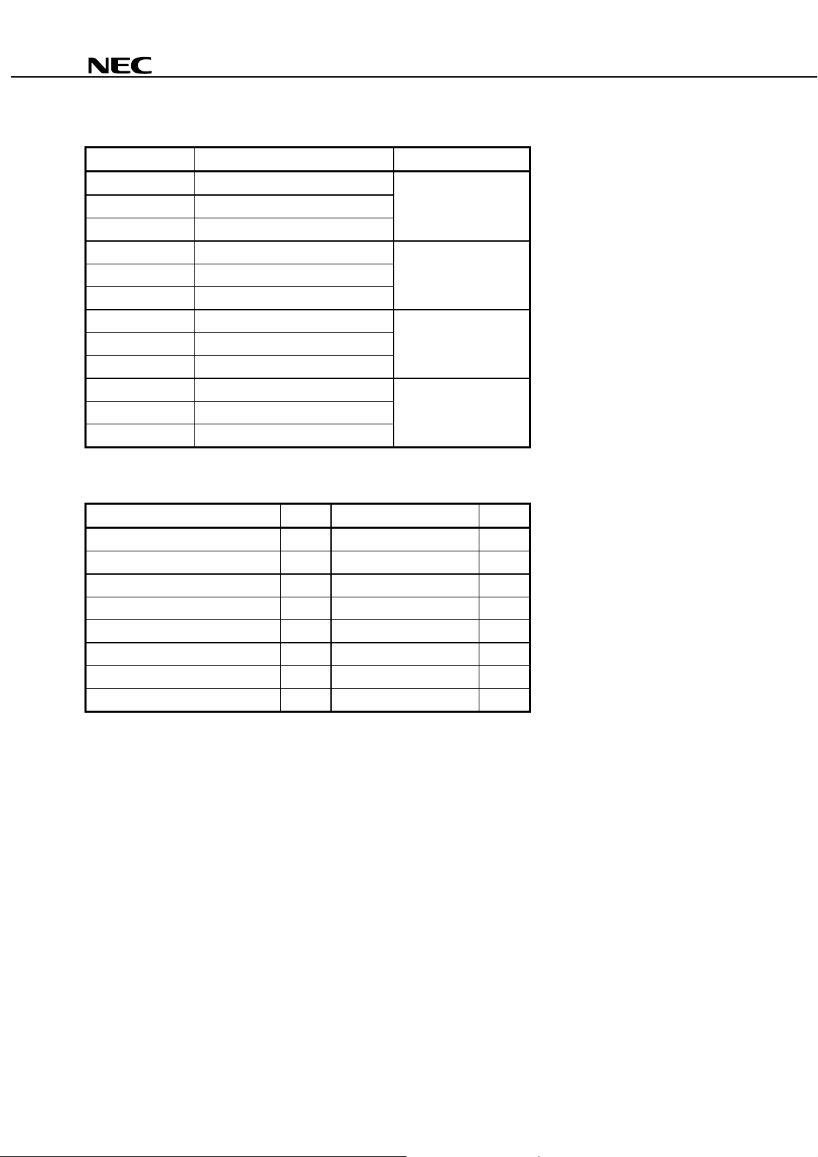
ORDERING INFORMATION
Part Number Available Connector Flange Type
NDL7605PC With FC-UPC Connector No Flange
NDL7605PD With SC-UPC Connector
NDL7605PX With SC-A PC Connector
NDL7605P1C With FC-UPC Connector Flat Mount Flange
NDL7605P1D With SC-UPC Connector
NDL7605P1X With SC-A PC Connector
NDL7605P2C With FC-UPC Connector Vertical Flange
NDL7605P2D With SC-UPC Connector
NDL7605P2X With SC-A PC Connector
NDL7605P4C With FC-UPC Connector Lead Bend
NDL7605P4D With SC-UPC Connector
NDL7605P4X With SC-A PC Connector
ABSOLUTE MAXIMUM RATINGS (T
C
= 25 °
°°
°C, unless otherwise specified)
Parameter Symbol Ratings Unit
Optical Output Power from Fiber P
f
5mW
Forward Current of LD I
F
I
th
+ 50 mA
Reverse Voltage of LD V
R
2.0 V
Forward Current of PD I
F
10 mA
Reverse Voltage of PD V
R
15 V
Operating Case Temperature T
C
−
40 to +85
°
C
Storage Temperature T
stg
−
40 to +85
°
C
Lead Soldering Temperature (10 s) T
sld
260
°
C
Data Sheet P14039EJ2V0DS00
4
NDL7605P Series
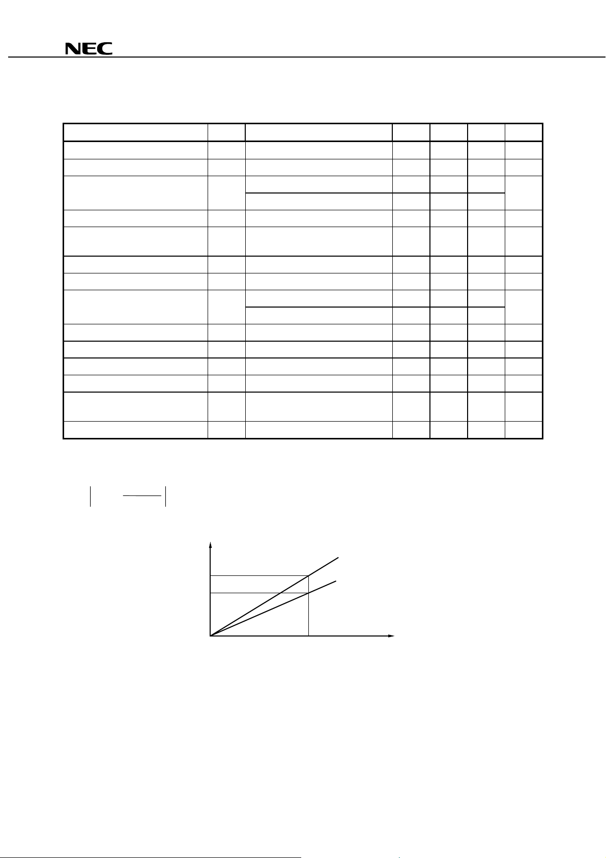
ELECTRO-OPTICAL CHARACTERISTICS
(T
C
= 25 °
°°
°C, Optical Reflection ≤
≤≤
≤ −
−−
−50 dB, unless otherwise specified)
Parameter Symbol Conditions MIN. TYP. MAX. Unit
Forward Voltage V
F
I
F
= 30 mA 0.9 1.1 1.3 V
Optical Output Power from Fiber P
f
CW 2.0 mW
Threshold Current I
th
CW 15 30 mA
CW, T
C
= 85
°
C4060
Differential Effi c i ency from Fiber
η
d
P
f
= 2.0 mW 0.080 0.200 W/A
Temperature Dependence of
Differential Effi c i ency from Fiber
∆η
d
P
f
= 2.0 mW,
η
(85
°
C) /
η
(25
°
C)
−
3.0 dB
Peak Emission Wavel ength
λ
p
P
f
= 2.0 mW, RMS (
−
20 dB) 1 290 1 310 1 330 nm
Side Mode Suppression Ratio SMSR P
f
= 2.0 mW 30 dB
2nd Order Inter-modulation Distort i on IMD2
*1
−
50 dBc
*1
, T
C
=
−
40 to +85
°
C
−
45
3rd Order Inter-modulation Distort i on IMD3
*1
, T
C
=
−
40 to +85
°
C
−
60 dBc
Carrier to Noise Ratio CNR
*1
, T
C
=
−
40 to +85
°
C
52 dB
Monitor Current I
m
V
R
= 5 V, P
f
= 2.0 mW 100 500 1 000
µ
A
Dark Current I
D
V
R
= 5 V 0.1 10 nA
Tracking Error
γ
*2
I
m
= const., P
f
= 2.0 mW,
T
C
=
−
40 to +85
°
C
1.5 dB
Optical Isolation ISO 30 dB
*1
Conditions: P
f
= 2.0 mW, T
C
= 25 °C, 2 channel unmodulated carriers 13 MHz and 19 MHz,
Optical Reflection = −50 dB, Optical Loss = 7 dB, OMI = 10 %/ch
*2
γ = 10 log
I
m
P
f
(mW)
P
f
2.0
I
m
(@ P
f
(25 ˚C) = 2.0 mW)
0
T
C
= –40 to +85 ˚C
T
C
= 25 ˚C
P
f
2.0 mW
 Loading...