


 Loading...
96M11680
Digital Photoelectric Sensor
PS-N10 Series
Instruction Manual
Read this instruction manual before using the product in order to achieve maximum performance. Follow instruction or you may be exposed to hazards.
Keep this instruction manual in a safe place after reading it so that it can be used at any time.
|
|
|
|
|
It indicates a hazardous situation which, if not avoided, will result in |
|
|
DANGER |
|
||
|
|
|
death or serious injury. |
||
|
|
|
|
|
|
|
|
|
|
|
It indicates a hazardous situation which, if not avoided, could result in |
|
|
WARNING |
|
death or serious injury. |
|
|
|
|
|
|
|
|
|
|
|
|
It indicates a hazardous situation which, if not avoided, could result in |
|
|
CAUTION |
|
||
|
|
|
minor or moderate injury. |
||
|
|
|
|
|
|
|
|
|
|
|
It indicates a situation which, if not avoided, could result in product |
|
|
NOTICE |
|
||
|
|
|
damage as well as property damage. |
||
|
|
|
|
|
|
|
|
|
|
|
|
|
|
|
|
|
|
|
|
|
|
|
It indicates cautions and limitations that must be followed during oper- |
|
|
Important |
|
|
|
|
|
|
ation. |
||
|
|
|
|
|
|
|
|
|
|
|
|
|
|
|
It indicates additional information on proper operation. |
||
|
|
Point |
|
||
|
|
|
|
|
|
|
|
Reference |
It indicates tips for better understanding or useful information. |
||
|
|
||||
|
|
|
|
|
|
See "PS-N10 Series User's Manual" for details on the features of the PS-N10 series and detailed instructions for configuration.
Safety Information for PS-N10 Series.
•This product is only intended to detect object(s). Do not use this product for the purpose of protecting a human body or a part of the human body.
WARNING • This product is not intended for use as an explosion-proof product. Do not use this product in a hazardous location and/or potentially explosive atmosphere.
•This product uses DC power. Do not apply AC power. The product may explode or burn if an AC voltage is applied.
•Do not wire the amplifier line along with power lines or high-ten- sion lines, as the sensor may malfunction or be damaged due to noise.
•When using a commercially available switching regulator, NOTICE ground the frame ground terminal and ground terminal.
•Do not use the PS-N10 series outdoors, or in a place where extraneous light can enter the light-receiving element directly.
•Due to individual dispersion characteristics and the difference in sensor head models, the maximum sensing distance or displayed value may not be the same on all units.
Precautions on Regulations and Standards
CSA Certificate
PS-N10 series complies with the following CSA and UL standards and has been certified by CSA (Class 2252 05 / Class 2252 85). (CSA mark is attached only to the sensor amplifier certified by CSA.)
•Applicable standard: CAN/CSA C22.2 No.61010-1
UL61010-1
Pollution Degree: 3
Overvoltage Category: I
•Use the following power supply.
CSA/UL certified power supply that provides Class 2 output as defined in the CEC (Canadian Electrical Code) and NEC (National Electrical Code), or CSA/UL certified power supply that has been evaluated as a Limited Power Source as defined in CAN/ CSA-C22.2 No. 60950-1/ UL60950-1
•Use this product at the altitude of 2000 m or less.
•Indoor use only.
•The sensor head cable and the sensor head connection cable must be installed with avoiding mechanical damage (e.g.: crushing).
•The power/input-output cable for amplifier unit is for internal wiring only. The amplifier must be installed inside of an approved enclosure or install power/input-output cable for amplifier with approved protection.
•The following cables are rated 30 V.
-sensor head cable
-sensor head connection cable
-power/input-output cable for amplifier unit
Install these cables where it is separated from the circuit over 30 V.
CE Marking
Keyence Corporation has confirmed that this product complies with the essential requirements of the applicable EC Directive, based on the following specifications.
Be sure to consider the following specifications when using this product in a member state of the European Union.
z EMC Directive (2004/108/EC)
• Applicable standard EMI : 60947-5-2, Class A EMS : 60947-5-2
•When connecting with the NU-CL1, always install in a conductive enclosure (control panel, etc.), and wrap a ferrite core (E04SR401938 manufactured by Seiwa Electric Mfg. Co., Ltd.) one turn around the sensor head cable.
•When extending the Sensor Head Cable of the PS-47(C)/49(C)/05/52(C)/55(C)/56/58, cover the entire Sensor Head Cable with conductive piping (for example with metal piping). Also, ground the end part of the piping (the sensor amplifier side).
Remarks: These specifications do not give any guarantee that the end-product with this product incorporated complies with the essential requirements of the EMC Directive. The manufacturer of the end-product is solely responsible for the compliance of the end-product itself according to the EMC Directive.
Included Accessories
Sensor Amplifier
Instruction manual x 1
Sensor head connector x 1
1

Sensor Head
z PS-45
Mounting bracket set
Receiver
Mounting bracket x 1 Transmitter Plate nut x 1
M3 x 12 screw x2
z PS-47/PS-47C*1
Transmitter
Receiver
z PS-49/PS-49C*1
Transmitter
Receiver
z PS-52/PS-52C*1
Transmitter (T) Receiver (R)
Nut x 4
Spring washer x 4
Flat washer x 4
M2 x 10 screw x 4
z PS-56
Transmitter (T) Receiver (R)
Nut x 4
Spring washer x 4
Flat washer x 4
M2 x 10 screw x 4
z PS-201/PS-201C*1
Transmitter(T) Receiver (R) |
Mounting bracket x 2 |
z PS-205
Receiver
Transmitter
z PS-46
Receiver
Transmitter
Nut x 2
Spring washer x 2
Flat washer x 2
M2 x 10 screw x 2
z PS-48
Mounting bracket x 1
Receiver
Transmitter
z PS-05
Transmitter (T) |
Receiver (R) |
|
|
|
Nut x 2 |
|
|
|
Spring washer x 2 |
For fixing the head |
|
|
Flat washer x 2 |
||
|
|
||
|
M3 x 14 screw x 2 |
|
|
|
Spring washer x 4 |
For fixing the holder |
|
Holder |
M3 x 10 screw x 4 |
||
|
z PS-55/PS-55C*1
Transmitter (T) Receiver (R)
z PS-58
Transmitter (T) Receiver (R) |
Mounting bracket x 2 |
z PS-202
Transmitter (T) Receiver (R) |
Mounting bracket x 2 |
z PS-206
Receiver
Transmitter
*1 A sensor head connector is attached to the end of the cable for the sensor heads with model names containing the suffix C.
2
PS-N10 Series Quick Start
Quick Start
Fine sensitivity adjustment
Up Down
Mode/Output *2
Press the [MODE] button once, then
use |
to select L-on or D-on |
Preset function
 Configure easily SEL M
  with a single press
when receiving light
Setting value Light intensity
Power select switch *1
Sensitivity setting
SEL M
Standard MEGA (fixed)
Press once each for workpiece/no workpiece
*1 Not available for 0-line types.
*2 Press and hold the [MODE] button to make advanced setting changes.
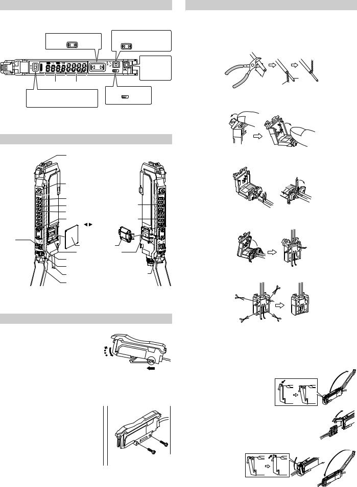
Names of Each Part of the Main Unit and Expansion Unit
Head lock lever
Power selection switch
SET button (SET)

 Operation status indicators
PST indicator |
Sub screen |
|
DTM indicator |
(Displayed in green) |
|
Digital display |
Main screen |
|
|
|
|
Manual button |
(Displayed in red) |
|
( |
) |
|
Expansion protective cover
Expansion connector
MODE button (MODE)
Preset button (PRESET)
Cable* |
Power select switch |
Dust cover |
|
*On the PS-N11Cx / N12Cx, this is an M8 connector rather than a cable. Not available for 0-line types.
Mounting Unit
Mounting on a DIN Rail
1 |
Align the claw at the bottom of the main body |
3 |
|
||
|
with the DIN rail, as shown on the right. |
|
|
While pushing the main body in the direction |
2 |
|
of the arrow 1, push down in the direction of |
|
|
|
|
2 |
arrow 2. |
|
To dismount the sensor, raise the main body |
1 |
|
|
in the direction of the arrow 3 while pushing the main body in the direction of arrow 1.
Installation on a Wall (Main Unit Only)
1 Attach the unit to the optional mounting bracket (OP-73880), and secure with two M3 screws as shown on the right.
Connecting the Sensor Head to the Sensor Amplifier
Installing the Sensor Head Connector
1 Process the cable ends as shown below. The core wire conductors are stripped so that they are exposed at the time of shipment. Be sure to process the cables without removing the insulation from the cable ends.
10 mm or longer
Cable core
Shielded wire
2 Move the upper left part of the connector in the direction of the arrow and then open the connector.
3 Fully insert the cables with the shielded wires standing upright. Next, bend the shielded wires along the grooves in the direction of the arrow.
Red wire
White wire
4 Close the connector to crimp the cables. Return the upper part of the connector to its original position and then lock it.
5 Using nippers, cut off the ends of cables protruding from the connector.
|
|
|
Crimp the cables no more than three times. Excessively crimping the |
|
NOTICE |
|
|
|
|
cables may result in a bad connection. |
|
|
|
|
|
|
|
|
|
Connecting the Sensor Head
1 Open the dust cover, and move the head lock lever down.
2 Lift the hook up, and insert the connector completely.
3 Lower the hook to the position shown in the drawing, and secure the head lock lever by pushing up.
3
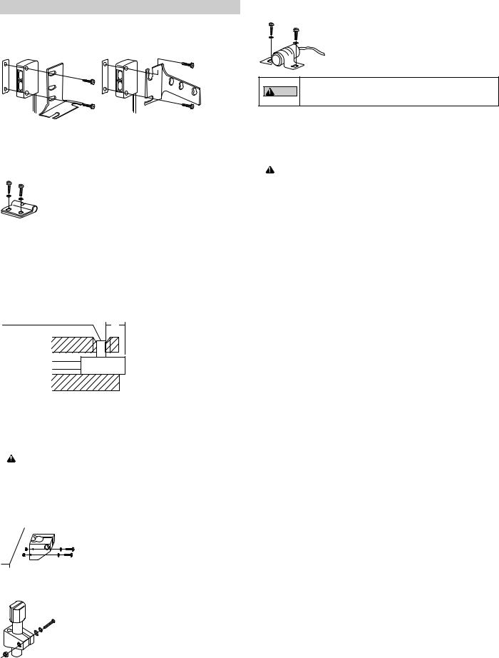
Mounting the Sensor Head
PS-45
Use the supplied fixing brackets. There are two ways to mount the sensor head. Make sure the tightening torque does not exceed 0.6 Nm.
PS-201(C)/202
Use the supplied fixing bracket or similar bracket. Install the M3 screws.
• Do not use setscrews to install the bracket.
CAUTION • Do not bend the 20 mm cable that runs from the end of the sensor head. Maintain a minimum bend radius of 25 mm.
PS-46/52(C)/56
Use the supplied screws or other similar screws. Make sure the tightening torque does not exceed the following values:
PS-46/56: 0.3 Nm or less PS-52: 0.15 Nm or less
PS-47(C)/49(C)/55(C)
Install the M3 screws. Make sure the tightening torque does not exceed 0.6 Nm.
PS-48/58
Install the M3 screws when using the supplied fixing brackets.
Make sure to observe the following requirements when using setscrews to mount the sensor head:
M3 setscrew (flat or dented head)
L
|
Model |
|
L |
|
Tightening torque |
|
||
|
|
|
|
|
|
|
|
|
|
PS-48 |
|
5 mm or longer |
|
0.15 Nm or less |
|
||
|
|
|
|
|
|
|
|
|
|
PS-58 |
|
7 mm or longer |
|
|
|||
|
|
|
|
|
||||
|
|
|
|
|
|
|
|
|
|
|
|
|
|
|
|||
|
|
|
|
Note If you place the reflective |
PS-48 in the mounting hole, it is |
|||
|
CAUTION |
|
|
affected by the light reflected from inside the hole. Place the front side |
||||
|
|
|
|
of the PS-48 so that it sticks out of the mounting hole, as shown above. |
||||
|
|
|
|
|
|
|
|
|
PS-05
When installing the holder, use the supplied screws and spring washers or other similar parts, as shown on the right. Make sure the tightening torque does not exceed 0.5 Nm.
When fixing the PS-05 to the holder, use the supplied screw, nuts, spring washer, and flat washer or other similar parts, as shown on the right. Make sure the tightening torque does not exceed 0.5 Nm.
PS-205/206
Install the M4 screws. Make sure the tightening torque does not exceed 0.5 Nm.
|
|
|
Do not bend the 20 mm cable that runs from the end of the sensor |
|
CAUTION |
|
|
|
|
head. Maintain a minimum bend radius of 25 mm. |
|
|
|
|
|
4
Loading...