


7800 SERIES EC7895A, RM7895A
Relay Module
GENERAL
The Yamatake Honeywell EC7895A and RM7895 is a microprocessor based integrated burner control for automatically fired gas, oil, or combination fuel single burner applications. The RM7895 consists of the Relay Module. Subbase, Amplifier and Purge Card. Options include Keyboard Display Module, Personal Computer Interface, DATA CONTROLBUS MODULE™, Remote Display Module, and COMBUSTION SYSTEM MANAGER™ Software.
The EC7895 and RM7895 are programmed to provide a level of safety, functional capability and features beyond the capacity of conventional controls.
Functions provided by the EC7895 and RM7895 include automatic burner sequencing, flame supervision, system status indication, system or self-diagnostics and troubleshooting.
PRODUCT DATA
•Dependable, long-term operation provided by microcomputer technology.
•First-out annunciation and system diagnostics provided by a 2 row by 20 column Vacuum Fluorescent Display (VFD) located on the optional Keyboard Display Module.
•Five (LEDs) for sequence information.
•Interchangeable plug-in flame amplifiers.
•Local or remote annunciation of EC7895 and RM7895 operation and fault information.
•Nonvolatile memory; EC7895 and RM7895 retain history files and sequencing status after loss of power.
•Remote reset (optional).
•Report generation (optional).
•Selectable recycle or lockout on loss of airflow.
•Selectable recycle or lockout on loss of flame.
•Shutter drive output.
•Burner controller data (optional):
—Flame signal strength.
—Hold status.
—Lockout/alarm status.
—Sequence status.
—Sequence time.
—Total cycles of operation.
—Total hours of operation.
—Fault history providing for the six most recent faults:
•Cycles of operation at the time of the fault.
•Fault message and code.
•Hours of operation at the time of the fault.
•Sequence status at the time of the fault.
•Sequence time at the time of the fault.
—Diagnostic information:
•Device type.
•Flame amplifier type.
•Flame failure response time.
•Manufacturing code.
•On/Off status of all digital inputs and outputs.
•Selected prepurge time.
•Software revision and version of EC7895 and RM7895 and optional Keyboard Display Module.
•Status of configuration jumpers.
FEATURES
•Safety features:
—Airflow switch check.
—Closed loop logic test.
—Dynamic AMPLI-CHECK®.
—Dynamic input check.
—Dynamic safety relay test.
—Dynamic self-check logic.
—Internal hardware status monitoring.
—Tamper resistant timing and logic.
•Access for external electrical voltage checks.
•Application flexibility.
•Communication interface capability.
|
Contents |
General ......................................................................................... |
1 |
Features ........................................................................................ |
1 |
Specifications ................................................................................ |
2 |
Ordering Information ..................................................................... |
2 |
Principal Technical Features ......................................................... |
8 |
Safety Provisions .......................................................................... |
8 |
Installation ..................................................................................... |
9 |
Wiring ............................................................................................ |
11 |
Assembly ...................................................................................... |
14 |
Operation ...................................................................................... |
17 |
Checkout ....................................................................................... |
20 |
Troubleshooting ............................................................................ |
26 |
Copyright © 1996 Honeywell Inc. • All Rights Reserved
X-XX UL |
65-0205 |

7800 SERIES EC7895A, RM7895A RELAY MODULE
SPECIFICATIONS
Model:
RM7895A
Electrical Ratings, see Table 1A:
Voltage and Frequency: 100 Vac (+10/-15%), 50 or 60 Hz (+/- 10%). 1
Power Dissipation: RM7895: 10W maximum. Maximum Total Connected Load: 2000 VA.
Fusing Total Connected Load: 20A maximum, type FRN or equivalent.
Table 1A. RM7895A Terminal Ratings.
|
|
|
|
Terminal No. |
Description |
|
Ratings |
G |
Flame Sensor Ground |
|
|
Earth G |
Earth Ground2 |
|
|
L2(N) |
Line Voltage Common |
|
|
3 |
Alarm |
100 |
Vac, 1A pilot duty. |
4 |
Burner Motor |
100 |
Vac, 9.8 AFL, 58.8 ALR (inrush). |
5 |
Line Voltage Supply (L1) |
100 |
Vac (+10/-15%), 50 or 60 Hz (+/- 10%).3,4 |
6 |
Burner Controller and Limits |
100 |
Vac, 1 mA. |
7 |
Airflow Interlock |
100 |
Vac, 9A. |
8 |
Pilot Valve/Ignition |
100 |
Vac, 4.5A ignition and 50VA pilot duty.4 |
9 |
Main Fuel Valve |
100 |
Vac, 2A pilot duty.5 |
10 |
Ignition |
100 |
Vac, 4.5A ignition.4 |
F(11) |
Flame Sensor |
60 to 220 Vac, current limited. |
|
12 |
Unused |
|
|
13 |
Unused |
|
|
14 |
Unused |
|
|
15 |
Unused |
|
|
16 |
Unused |
|
|
17 |
Unused |
|
|
18 |
Unused |
|
|
19 |
Unused |
|
|
20 |
Unused |
|
|
21 |
Unused |
|
|
22 |
Shutter |
100 |
Vac, 0.5A |
1Range of allowable operating frequency: 45 to 66 Hz.
2The 7895 must have an earth ground providing a connection between the subbase and the control panel or the equipment. The earth ground wire must be capable of conducting the current to blow the 20A fuse (or breaker) in event of an internal short circuit. The 7895 needs a low impedance ground connection to the equipment frame which, in turn, needs a low impedance connection to earth ground. For a ground path to be low impedance at RF frequencies, the connection must be made with minimum length conductors that have maximum surface areas. Wide straps or brackets rather than leadwires are preferred. Be careful to verify that mechanically tightened joints along the ground path, such as pipe or conduit threads or surfaces held together with fasteners, are free of nonconductive coatings and are protected against mating surface corrosion.
32000 VA maximum connected load to 7895 Assembly.
4Can also be 100 Vac, 1A pilot duty.
5Can also be 65 VA pilot duty with motorized valve, 1150 VA inrush, 460 VA open, 250 VA hold.
ORDERING INFORMATION
When purchasing replacement and modernization products from your TRADELINE® wholesaler or distributor, refer to the TRADELINE® Catalog or price sheets for complete ordering number.
If you have additional questions, need further information, or would like to comment on our products or services, please write or phone:
1.Your local Home and Building Control Sales Office (check white pages of your phone directory).
2.Home and Building Control Customer Relations Honeywell, 1885 Douglas Drive North Minneapolis, Minnesota 55422-4386
In Canada—Honeywell Limited/Honeywell Limitée, 35 Dynamic Drive, Scarborough, Ontario M1V 4Z9.
International Sales and Service Offices in all principal cities of the world. Manufacturing in Australia, Canada, Finland, France, Germany, Japan, Mexico, Netherlands, Spain, Taiwan, United Kingdom, U.S.A.
65-0205 |
2 |

|
|
7800 SERIES EC7895A, RM7895A RELAY MODULE |
||
|
|
|
||
Model: |
Electrical Ratings, see Table 1B: |
|||
EC7895 |
|
Voltage and Frequency: 200 Vac (+10/-15%), 50 or 60 Hz |
||
|
|
(+/- 10%). 1 |
||
|
|
Power Dissipation: EC7895: 10W maximum. |
||
|
|
Maximum Total Connected Load: 2000 VA. |
||
|
|
Fusing Total Connected Load: 20A maximum, type FRN or |
||
|
|
equivalent. |
||
|
Table 1B. EC7895A Terminal Ratings. |
|||
|
|
|
|
|
|
|
|
|
|
Terminal No. |
Description |
|
|
Ratings |
|
|
|
|
|
G |
Flame Sensor Ground |
|
|
|
|
|
|
|
|
Earth G |
Earth Ground2 |
|
|
|
L2 (N) |
Line Voltage Common |
|
|
|
|
|
|
|
|
3 |
Alarm |
|
200 |
Vac, 1A pilot duty. |
|
|
|
|
|
4 |
Burner Motor |
|
200 |
Vac, 4A at pF = 0.5, 20A inrush4 |
5 |
Line Voltage Supply (L1) |
|
200 |
Vac (+10/-15%), 50 or 60 Hz (+/- 10%).3,4 |
6 |
Burner Controller and Limits |
|
200 |
Vac, 1 mA. |
|
|
|
|
|
7 |
Airflow Interlock |
|
200 |
Vac, 9A. |
|
|
|
|
|
8 |
Pilot Valve/Ignition |
|
200 |
Vac, 4A at pF = 0.5, 20A inrush4 |
9 |
Main Fuel Valve |
|
200 |
Vac, 4A at pF = 0.5, 20A inrush4 |
10 |
Ignition |
|
200 |
Vac, 4A at pF = 0.5, 20A inrush4 |
F(11) |
Flame Sensor |
|
60 to 220 Vac, current limited. |
|
|
|
|
|
|
12 |
Unused |
|
|
|
|
|
|
|
|
13 |
Unused |
|
|
|
|
|
|
|
|
14 |
Unused |
|
|
|
|
|
|
|
|
15 |
Unused |
|
|
|
|
|
|
|
|
16 |
Unused |
|
|
|
|
|
|
|
|
17 |
Unused |
|
|
|
|
|
|
|
|
18 |
Unused |
|
|
|
|
|
|
|
|
19 |
Unused |
|
|
|
|
|
|
|
|
20 |
Unused |
|
|
|
|
|
|
|
|
21 |
Unused |
|
|
|
|
|
|
|
|
22 |
Shutter |
|
200 |
Vac, 0.5A |
|
|
|
|
|
1Range of allowable operating frequency 45 through 66 Hz.
2The EC7895 must have an earth ground providing a connection between the subbase and the control panel or the equipment. The earth ground wire must be capable of conducting the current to blow the 20A fuse (or breaker) in event of an internal short circuit. The RM7895 needs a low impedance ground connection to the equipment frame which, in turn, needs a low impedance connection to earth ground. For a ground path to be low impedance at RF frequencies, the connection must be made with minimum length conductors that have maximum surface areas. Wide straps or brackets rather than leadwires are preferred. Be careful to verify that mechanically tightened joints along the ground path, such as pipe or conduit threads or surfaces held together with fasteners, are free of nonconductive coatings and are protected against mating surface corrosion.
32000 VA maximum connected load to EC7895 Assembly.
4Total load current excluding burner/boiler motor and firing rate outputs cannot exceed 5A, 25A inrush.
3 |
65-0205 |

7800 SERIES EC7895A, RM7895A RELAY MODULE
Environmental Ratings: |
|
|
Weight: |
|
|
||
Ambient Temperature: |
|
|
RM7895 with Dust Cover: 1 pound 15 ounces, unpacked. |
||||
Operating: -40° F to 140° F. |
|
IMPORTANT |
|
|
|||
Storage: -60° F to 150° F. |
|
|
|
||||
Humidity: 85% RH continuous, noncondensing. |
|
Flame Detection System available for use with |
|||||
Vibration: 0.5G environment. |
|
|
EC7895 and RM7895. To select your Plug-in Flame |
||||
Dimensions: |
|
|
|
|
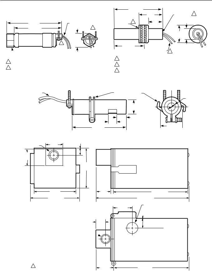
Signal Amplifier and applicable Flame Detector, see |
||
|
|
|
|
Table 2 and Fig. 3 through 5. |
|||
Refer to Fig. 1 and 2. |
|
|
|
|
|
|
|
|
|
Table 2. Flame detection systems (Figs. 3, 4, 5). |
|
||||
|
|
|
|
|
|
|
|
|
|
|
|
|
|
|
|
|
Plug-in Flame Signal Amplifiers |
|
|
Applicable Flame Detectors |
|||
|
|
|
|
Flame |
|
|
|
|
|
|
|
Failure |
|
|
|
|
|
Self- |
|
Response |
|
|
|
Type |
Color |
Checking |
Model |
Time |
Fuel |
Type |
Models |
Rectification |
Green |
No |
R7847A |
.8 or 3 sec |
Gas |
Rectifying Flame |
C7004, C7007, C7011 |
|
|
|
|
|
|
Rod Holdersa |
Complete Assemblies: |
|
|
|
|
|
|
|
C7008, C7009, Q179. |
|
|
No |
R7847A |
.8 or 3 sec |
Oil |
Rectifying |
C7003, C7010, C7013, |
|
|
|
|
|
|
Photocell |
C7014b |
|
|
No |
R7847A |
3 sec |
Gas, |
Ultraviolet |
C7012A,C.c |
|
|
|
|
|
Oil, Coal |
(Purple Peeper) |
|
|
|
Dynamic |
R7847Bd |
.8 or 3 sec |
Gas |
Rectifying Flame |
C7004, C7007, C7011 |
|
|
AMPLI- |
|
|
|
Rod Holdersa |
Complete Assemblies: |
|
|
CHECK® |
|
|
|
|
C7008, C7009, Q179. |
|
|
Dynamic |
R7847Bd |
.8 or 3 sec |
Oil |
Rectifying |
C7003, C7010, C7013, |
|
|
AMPLI- |
|
|
|
Photocell |
C7014b |
|
|
CHECK® |
|
|
|
|
|
|
|
Dynamic |
R7847Bd |
3 sec |
Gas, |
Ultraviolet |
C7012A,C.c |
|
|
AMPLI- |
|
|
Oil, Coal |
(Purple Peeper) |
|
|
|
CHECK® |
|
|
|
|
|
|
|
Dynamic |
R7847Ce |
3 sec |
Gas, |
Ultraviolet |
C7012E,F. |
|
|
Self-Check |
|
|
Oil, Coal |
(Purple Peeper) |
|
Infrared |
Red |
No |
R7848A |
3 sec |
Gas, |
Infrared |
C7015 |
|
|
|
|
|
Oil, Coal |
(Lead Sulfide) |
|
|
|
Dynamic |
R7848Bd |
3 sec |
Gas, |
Infrared |
C7015 |
|
|
AMPLI- |
|
|
Oil, Coal |
(Lead Sulfide) |
|
|
|
CHECK® |
|
|
|
|
|
Ultraviolet |
Purple |
No |
R7849A |
.8 or 3 sec |
Gas, Oil |
Ultraviolet |
C7027, C7035, |
|
|
|
|
|
|
(MiniPeeper) |
C7044.c |
|
|
Dynamic |
R7849Bd |
.8 or 3 sec |
Gas, Oil |
Ultraviolet |
C7027, C7035, |
|
|
AMPLI- |
|
|
|
(MiniPeeper) |
C7044.c |
|
|
CHECK® |
|
|
|
|
|
|
|
Dynamic |
R7861A |
3 sec |
Gas, |
Ultraviolet |
C7061 |
|
|
Self-Checkf |
|
|
Oil, Coal |
|
|
|
Blue |
Dynamic |
R7886Ae |
3 sec |
Gas, |
Ultraviolet |
C7076 |
|
|
Self-Checkg |
|
|
Oil, Coal |
(Adjustable |
|
|
|
|
|
|
|
Sensitivity) |
|
aOrder flame rod separately; see holder Instructions.
bUse only Honeywell Photocell, part no. 38316.
cThe C7012A,C, C7027, C7035 and C7044 Flame Detectors should be used only on burners that cycle on-off at least once every twenty-four hours. Appliances with burners that remain on continuously for twenty-four hours or longer should use the C7012E,F Flame Detector with the R7847C Amplifier or the C7076A,D Flame Detector with the R7886A Amplifier or the C7061 Flame detector with the R7861 Amplifier as the ultraviolet flame detection system.
dCircuitry tests the flame signal amplifier at least 12 times a minute during burner operation and shuts down the burner if the amplifier fails.
eCircuitry tests all electronic components in the flame detection system (amplifier and detector) 12 times a minute during burner operation and shuts down the burner if the detection system fails.
fWhen R7861 is used with EC7895, the application requires a step down transformer. See Fig. 14.
gUse with RM7895A only.
65-0205 |
4 |

7800 SERIES EC7895A, RM7895A RELAY MODULE
Sequence Timing For Normal Operation:
|
|
|
|
|
|
|
|
|
|
Flame Establishing Period |
|
|
|
|
|
|
|
Device |
Initiate |
Standby |
Purge |
Pilot |
Main |
|
|
|
|
|
|
EC7895A/RM7895A |
10 sec. |
* |
** |
4 or 10 sec. |
No |
|
|
|
|
|
|
*STANDBY and RUN can be an infinite time period.
**PURGE is determined by the ST7800A Purge Card selected.
Approval Bodies:
RM7895A:
Underwriters Laboratories Inc. listed: File no. MP268, Guide no. MCCZ.
Factory Mutual approved. EC7895A:
Factory Mutual approved.
Mounting:
Q7800A for panel mount or Q7800B for wall or burner mount.
Required Components:
Plug-in Flame Signal Amplifier, see Table 2.
Plug-in Purge Timer Cards: Selectable ST7800A, two seconds to 30 minutes.
Q7800A or Q7800B.
Accessories:
Optional:
Network Interface Unit,
Part No. Q7700A1014, 120V 50/60 Hz
Part No. Q7700B1004, 100V to 200V 50/60 Hz Network Interface ControlBus Module,
Part No. QS7800A1001. COMBUSTION SYSTEM MANAGER™,
Part No. ZM7850A1001.
ControlBus 5-Wire Electrical Connector, Part No. 203541.
DATA CONTROLBUS MODULE™, Part No. S7810A1009.
Dust Cover, Part No. 221729A. Flame Simulators:
UV Flame Simulator, Part No. 203659. Rectification Simulator, Part No. 123514A.
Keyboard Display Module, Part No. S7800A1001, English.
Keyboard Display Module, Part No. S7800A1118, Japanese.
Remote Display Mounting Bracket, Part No. 203765. Remote Display Power Supply, Part No. 203968A Plug-in. Remote Reset Module, Part No. 57820A1007.
Sixty-inch Extension Cable Assembly, Part No. 221818A.
BURNER |
|
|
CONTROL |
|
|
5 |
1 |
|
(127) |
||
|
||
POWER |
|
|
PILOT |
|
|
FLAME |
|
|
MAIN |
|
|
ALARM |
|
|
RESET |
|
|
5 (127) |
5-1/4 (133) |
|
|
||
1 REMOVE ONLY FOR TERMINAL TEST ACCESS. |
M11135 |
Fig. 1. Mounting dimensions of EC7895/RM7895 Relay Module and Q7800A Subbase in in. (mm).
5 |
65-0205 |

7800 SERIES EC7895A, RM7895A RELAY MODULE
BURNER
CONTROL
5
(127)
POWER
PILOT 1
FLAME
MAIN
ALARM
RESET
5 (127) |
6-3/32 (155) |
|
|
1 REMOVE ONLY FOR TERMINAL TEST ACCESS. |
M11134 |
Fig. 2. Mounting dimensions of EC7895/RM7895 Relay Module and Q7800B Subbase in in. (mm).
IGNITION |
|
|
|
ELECTRODE |
FLAME ROD |
|
|
(Q179C ONLY) |
CERAMIC |
|
|
|
INSULATORS |
1 (25) |
|
|
|
|
|
1-21/32 |
1-13/32 |
|
|
(42) |
(36) |
|
|
|
TARGET |
MOUNTING FLANGE |
3/4–14 NPT |
|
3/8 (10) |
||
|
7-7/32 |
|
|
|
|
|
|
|
|
(183) |
|
3-1/8 |
|
1-1/16 |
|
|
5-1/8 (130) |
|
(79) |
|
1/2 (13) |
3-3/4 |
|
||
|
(27) |
|
||||
|
|
(95) |
|
|||
|
|
|
|
|
|
|
|
|
|
|
|
3-7/16 |
|
|
|
3/32 (2) |
|
(87) |
|
|
|
|
11/16 |
|
|
||
|
|
|
|
|
|
|
25/32 |
25/32 |
|
|
(18) |
|
|
17/32 |
|
|
|
|
||
(20) |
(20) |
|
THREADED |
|
|
|
(14) |
|
1/2–14 NPSM |
|
|||
|
|
|
MOUNTING |
|
||
|
2-25/32 |
|
|
5-1/4 (133) |
|
|
|
|
|
HOLES (2)– |
LEADWIRES |
|
|
BRACKET |
(62) |
|
|
10-32 UNF |
FACEPLATE |
M1962A |
|
|
|
M1983 |
|
|
|
Q179 |
C7012A,C,E,F |
|
13/16 (21) |
1-1/4 (32) |
1-3/8 (35) |
2
(51)
1-3/4
(45)
1-1/4 (32) |
1-5/16 (33) |
5/16 |
|
|
|
(8) |
|
C7013A |
|
C7014A |
M1847 |
Fig. 3. Rectification detectors.
65-0205 |
6 |
7800 SERIES EC7895A, RM7895A RELAY MODULE
4-1/8 (105)
4 (102) |
6 FOOT (1.83 METER) |
|
LEADWIRES (2) |
3-1/2 (89) |
1 |
|
1-1/16 |
2 |
(27) |
|
 COLLAR WITH 1/2-14 NPSM
INTERNAL THREADS
1MODEL AVAILABLE WITH 24 FOOT (7.32 METER) LEADWIRES.
2MODELS AVAILABLE WITH SPUD CONNECTOR (1/2-14 NPSM INTERNAL
THREADS) INSTEAD OF CLAMP TYPE CONNECTOR. |
M1943A |
COLLAR WITH |
2 (51) |
1/2-14 NPSM 2 |
|
1–11-1/2 NPSM |
1-3/16 |
INTERNAL THREADS |
|
INTERNAL |
|
|
|
1 |
(30) |
|
|
THREADS |
|
||
|
|
|
|
|
|
|
31/32 |
|
|
|
1-1/2 (25) |
|
|
|
(38) |
2-5/8 (67) |
6 FOOT |
|
|
[1.83 METER] |
|
||
INSERTION DEPTH |
|
||
LEADWIRES (2) |
3 |
||
|
|
|
|
1DIN APPROVED C7035A1064 HAS 1-11 BSP.P1 INTERNAL THREADS.
2DIN APPROVED C7035A1064 HAS 1/2-14 BSP-F INTERNAL THREADS.
3MODEL AVAILABLE WITH 12 FOOT [3.66 METER] LEADWIRES. M1945A
C7027 |
C7035 |
|
|
6 FOOT [1.83 METER] |
|
LEADWIRES (2) |
MOUNTING BRACKET |
3/8
(10)
7/8
(22)
9/16
(14)
1/2
(13)
3-5/8 (92)
1-27/64 
(36) M1944A
C7044
|
2-1/4 |
1-1/16 (27) |
|
|
|
1 INCH NPT |
(57) |
|
2-1/4 |
|
|
(57) |
|
|
|
|
4 |
|
|
(102) |
4 (102) |
2-5/16 |
1-13/32 (188) |
|
(58) |
|||
|
|
||
4-27/32 (123) |
|
10-9/32 (261) |
|
|
|
7/8 (22) OPENING |
|
|
3/4 (19) |
FOR 1/2-INCH CONDUIT |
|
|
|
29/32 (23) |
1-19/32
(41)
3/8 INCH NPT
1ALLOW 9 INCHES (228 MILLIMETERS) CLEARANCE TO SWING OUT THE DETECTOR FOR LENS CLEANING OR SERVICING.
2-11/16 |
7-5/8 (194) |
(68) |
M5083A |
C7076A
Fig. 4. Ultraviolet detectors in in. (mm).
7 |
65-0205 |

7800 SERIES EC7895A, RM7895A RELAY MODULE
|
|
11-13/16 (300) |
|
|
1 INCH NPT |
2-5/32 |
7-13/16 (198) |
1-27/32 |
5-13/16 (147) |
(55) |
(47) |
|||
15/16 [24] DIA. |
|
|
|
|
 5-13/16 6-7/32 (147) (158)
2-1/2
(64) 6-19/32
(168)
1 (25) |
15/16–18 UNC |
|
2 (51) |
(2 EACH) |
C7076D |
|
M5084A
Fig. 4. Ultraviolet detectorsin in. (mm) (Continued).
CELL MOUNT |
HEAT BLOCK |
||
|
1-5/8 (41) |
|
|
2-3/4 |
1-1/16 (27) |
||
(70) |
|||
|
|
||
|
1-1/4 |
1-1/4 |
|
|
(32) |
||
|
(32) |
||
|
|
||
2 LEADS IN A |
|
|
|
48 INCH (1.2 METER) |
APERTURE |
|
|
FLEXIBLE CONDUIT |
|
||
3/4-14 |
3/4-14 NPSM |
||
|
|||
BUSHING WITH |
NPSM |
INTERNAL |
|
MAGNIFYING LENS |
COLLAR, 3/4-14 NPSM |
THREADS |
|
|
INTERNAL THREADS |
|
|
C7015 |
M1982A |
||
Fig. 5. Infrared detector in in. (mm).
PRINCIPAL TECHNICAL FEATURES
The EC7895 or RM7895 provides all customary flame safeguard functions while providing significant advancements in the areas of safety, annunciation and system diagnostics.
d.Main valve terminal is energized.
e.Internal system fault occurred.
f.Purge card is removed.
g.Purge card is bad.
4.Pilot Flame Establishing Period (PFEP)
a.Airflow lockout feature is enabled and the airflow switch opens.
b.Ignition/pilot valve terminal is not energized.
c.No flame present at end of PFEP.
d.Main valve terminal is energized.
e.Internal system fault occurred.
f.Purge card is removed.
g.Purge card is bad.
5.Run Period
a.No flame present.
b.Airflow lockout feature is enabled and the airflow switch opens.
c.Main valve terminal is not energized.
d.Internal system fault occurred.
e.Purge card is removed.
f.Purge card is bad.
Safety Shutdown (Lockout) Occurs If:
1.Initiate Period
a.Purge card is not installed or removed.
b.Purge card is bad.
c.Configuration jumpers have been changed (after 200 hours).
d.AC line power errors occurred, see Operation.
e.Four minute INITIATE period was exceeded.
2.Standby Period
a.Flame signal is present after 40 seconds.
b.Ignition/pilot valve/intermittent pilot valve terminal is energized.
c.Main valve terminal is energized.
d.Internal system fault occurred.
e.Purge card is not installed or removed.
f.Purge card is bad.
3.Prepurge Period
a.Airflow lockout feature is enabled and the airflow switch does not close after ten seconds or within the specified purge card timing.
b.Flame signal is detected after 30 seconds.
c.Ignition/pilot valve/intermittent pilot valve terminal is energized.
SAFETY PROVISIONS
Internal Hardware Status Monitoring
The EC7895 or RM7895 checks the purge card for correct parity to prevent purge timing shifts and circuitry failures. It also analyzes the integrity of the configuration jumpers and internal hardware. The POWER LED blinks every four seconds, signifying an internal hardware check.
Closed Loop Logic Test
The test verifies the integrity of all safety critical loads, terminals 8, 9, 10 and 21. If the loads are not energized properly; i.e., the main valve terminal is powered during PREPURGE, the EC7895 or RM7895 locks out on safety shutdown. The EC7895 or RM7895 must react to input changes but avoid the occurrence of nuisance shutdown events. Signal conditioning is applied to line voltage inputs to verify proper operation in the presence of normal electrical line noise such as transient high voltage spikes or short periods of line dropout. Signal conditioning is tolerant of synchronous noise (line noise events that occur at the same time during each line cycle).
65-0205 |
8 |

7800 SERIES EC7895A, RM7895A RELAY MODULE
Dynamic Ampli-Check®
Dynamic AMPLI-CHECK® circuitry tests the flame signal amplifier during burner operation and shuts down the EC7895 or RM7895 if the flame amplifier fails.
Verified Spark Termination
The ignition terminal is monitored to assure early spark termination (ten seconds ignition and pilot and ten seconds pilot and main only).
Dynamic Flame Amplifier and Shutter Check
Self-checking circuitry tests all electronic components in the flame detection system and amplifier 10 to 12 times per minute and shuts down the EC7895 or RM7895 if the detection system fails.
Dynamic Input Check
All system input circuits are examined to assure that the EC7895 or RM7895 is capable of recognizing the true status of external controls, limits and interlocks. If any input fails this test, a safety shutdown occurs and the fault is annunciated.
Dynamic Safety Relay Test
Checks the ability of the dynamic safety relay contact to open and close. Verifies that the safety critical loads, terminals 8, 9, 10 and 21, can be de-energized, as required, by the Dynamic Self-Check logic.
Dynamic Self-Check Safety Circuit
The microcomputer tests itself and related hardware, and at the same time, the safety relay system tests the microcomputer operation. If a microcomputer or safety relay failure occurs and does not allow proper execution of the selfcheck routine, safety shutdown occurs and all safety critical loads are de-energized.
Expanded Safe-Start Check
The conventional safe-start check, which prevents burner start-up if flame is indicated at start-up, is expanded to include a flame signal check during STANDBY, an airflow switch check and a safety critical load check.
Off Cycle (Standby or Prepurge) Flame Signal Check
The flame detection subsystem (flame detector and amplifier) is monitored during STANDBY. If a flame simulating condition or an actual flame exists, a system hold occurs and start-up is prevented. If the flame signal exists at any time after the first 40 seconds of STANDBY, a safety shutdown occurs and is annunciated. A shutter-check amplifier and self-checking detector are energized for the first 40 seconds during STANDBY and the last two seconds before exiting STANDBY. If a flame exists, a safety shutdown occurs. An AMPLICHECK® Amplifier is energized continually through STANDBY and PREPURGE to detect any possibility of a runaway detector or a flame. If a flame exists, a safety shutdown occurs. A standard amplifier is energized continually through STANDBY and PREPURGE; if a flame exists, a safety shutdown occurs.
Tamper Resistant Timing and Logic
Safety and logic timings are inaccessible and cannot be altered or defeated.
First-Out Annunciation AND Self-Diagnostics
Sequence Status Lights (LEDs) provide positive visual indication of the program sequence: POWER, PILOT, FLAME, MAIN and ALARM. The green POWER LED blinks every four seconds, signifying that the RM7895 hardware is running correctly.
Optional multi-function Keyboard Display Module shows elapsed time during PREPURGE, PILOT IGN and MAIN IGN. As an additional troubleshooting aid, it provides sequence timing, diagnostic information and historical information when a safety shutdown or hold or normal operation occurs.
First-out Annunciation reports the cause of a safety shutdown or identifies the cause of a failure to start or continue the burner control sequence with text and numbered code via the optional Keyboard Display Module. It monitors all field input circuits, including the flame signal amplifier. The system distinguishes 43 modes of failure and detects and annunciates difficult-to-find intermittent failures.
Self-Diagnostics add to the First-out Annunciation by allowing the EC7895 or RM7895 to distinguish between field (external device) and internal (system related) problems. Faults associated within the flame detection subsystem, EC7895 or RM7895 or Plug-in Purge Card are isolated and reported by the optional Keyboard Display Module. See the 7800 SERIES System Annunciation Diagnostics and Troubleshooting,
form 65-0118.
Airflow Switch Interlock
This interlock is typically connected to an airflow switch. The Airflow Interlock (ILK) input must close ten seconds into PREPURGE or within the specified purge card timing; otherwise, a recycle to the beginning of PRE-PURGE or lockout will occur, depending on how the airflow switch selectable jumper is configured (see Table 3 in Operation section).
INSTALLATION
 WARNING
FIRE OR EXPLOSION HAZARD CAN CAUSE PROPERTY DAMAGE, SEVERE INJURY, OR DEATH
To prevent possible hazardous burner operation, verification of safety requirements must be performed each time a control is installed on a burner.
9 |
65-0205 |
 Loading...