


Optimus™ 5900 RFID Mobile Computer
with Windows® CE 5.0
User’s Guide

Disclaimer
Honeywell International Inc. (“HII”) reserves the right to make changes in specifications and other information contained in this document without prior notice, and the reader should in all cases consult HII to determine whether any such changes have been made. The information in this publication does not represent a commitment on the part of HII.
HII shall not be liable for technical or editorial errors or omissions contained herein; nor for incidental or consequential damages resulting from the furnishing, performance, or use of this material.
This document contains proprietary information that is protected by copyright. All rights are reserved. No part of this document may be photocopied, reproduced, or translated into another language without the prior written consent of HII.
Web Address: www.honeywellaidc.com
Trademarks
Optimus and eBase are trademarks or registered trademarks of Hand Held Products, Inc. or Honeywell International Inc.
Microsoft, Windows, Windows Mobile, Windows CE, Windows NT, Windows 2000, Windows ME, Windows XP, ActiveSync, Outlook, and the Windows logo are trademarks or registered trademarks of Microsoft Corporation.
Other product names mentioned in this manual may be trademarks or registered trademarks of their respective companies and are the property of their respective owners.
Patents
For patent information, please refer to www.honeywellaidc.com/patents.
Other Trademarks
The Bluetooth trademarks are owned by Bluetooth SIG, Inc., U.S.A. and licensed to Honeywell International Inc.
©2012 Honeywell International Inc. All rights reserved.

Table of Contents
Chapter 1 - Agency Approvals
Label Locations.................................................................................................................... |
1-1 |
Safety & RF Approvals by Country: ..................................................................................... |
1-1 |
RF Terminal—802.11g and/or Bluetooth ............................................................................. |
1-1 |
Chapter 2 - Getting Started |
|
Out of the Box ...................................................................................................................... |
2-1 |
LED Indicators................................................................................................................ |
2-3 |
Desktop................................................................................................................................ |
2-4 |
Command Bar Icons ............................................................................................................ |
2-4 |
Chapter 3 - Terminal Hardware Overview |
|
Standard Terminal Configurations ....................................................................................... |
3-1 |
Front Panel Features ........................................................................................................... |
3-2 |
Display Backlight.................................................................................................................. |
3-3 |
Screen Backlight - Battery/External Power .................................................................... |
3-3 |
Keyboard Backlight .............................................................................................................. |
3-3 |
Using Screen Protectors ...................................................................................................... |
3-3 |
Back Panel Features............................................................................................................ |
3-7 |
Right Side Panel Features ................................................................................................... |
3-8 |
Installing Memory Cards ................................................................................................ |
3-8 |
Left Side Panel Features ..................................................................................................... |
3-9 |
Top Panel Features ............................................................................................................. |
3-9 |
Bottom Panel Features ...................................................................................................... |
3-10 |
Peripherals/Accessories for the Optimus 5900 RFID Terminal.......................................... |
3-11 |
Battery Power .................................................................................................................... |
3-11 |
Resetting the Terminal....................................................................................................... |
3-14 |
Soft Reset (Warm Boot) ............................................................................................... |
3-14 |
Hard Reset (Cold Boot)................................................................................................ |
3-14 |
Suspend Mode................................................................................................................... |
3-15 |
Changing the Memory Allocation ....................................................................................... |
3-15 |
Care and Cleaning of the Optimus 5900 RFID Terminal ................................................... |
3-15 |
Chapter 4 - Using the Keypad |
|
Overview .............................................................................................................................. |
4-1 |
Navigation Keys ................................................................................................................... |
4-1 |
Basic Keys ........................................................................................................................... |
4-2 |
Alpha/Numeric Modes.......................................................................................................... |
4-2 |
Alpha Indicators on the Number Keys............................................................................ |
4-2 |
Function Key Combinations ................................................................................................. |
4-3 |
CTRL Key Combinations ..................................................................................................... |
4-3 |
Program Buttons .................................................................................................................. |
4-4 |
iii

Chapter 5 - Using the UHF RFID Reader
Overview.............................................................................................................................. |
5-1 |
Configuring the RFID Output ............................................................................................... |
5-2 |
Reading Tags ...................................................................................................................... |
5-3 |
Tag Writing .......................................................................................................................... |
5-4 |
Tag Lock/Kill ........................................................................................................................ |
5-5 |
Kill.................................................................................................................................. |
5-5 |
Chapter 6 - Using the Image Engine |
|
Overview.............................................................................................................................. |
6-1 |
Available Image Engines ..................................................................................................... |
6-1 |
Depth of Field ................................................................................................................ |
6-1 |
Supported Bar Code Symbologies ..................................................................................... |
6-2 |
Activating the Engine........................................................................................................... |
6-3 |
Decoding ............................................................................................................................. |
6-3 |
Capturing Images ................................................................................................................ |
6-5 |
Chapter 7 - Communication |
|
Communication Options ...................................................................................................... |
7-1 |
Installing Additional Software .............................................................................................. |
7-1 |
ActiveSync Communication................................................................................................. |
7-1 |
Wireless Radios................................................................................................................... |
7-5 |
Connecting the Terminal to a Wireless Network............................................................ |
7-5 |
WLAN (802.11g Radio) ....................................................................................................... |
7-6 |
Setting the Auto Profile .................................................................................................. |
7-8 |
Turning Off the Wireless LAN ........................................................................................ |
7-8 |
Adding Programs from the Internet ..................................................................................... |
7-8 |
Chapter 8 - Bluetooth Handler |
|
Enabling the Bluetooth Radio .............................................................................................. |
8-1 |
Connecting to Other Devices............................................................................................... |
8-1 |
Pairing Bluetooth Devices ................................................................................................... |
8-1 |
Setting Up a Bluetooth Printer ............................................................................................. |
8-1 |
Setting Up a Connection to a Mobile Phone........................................................................ |
8-2 |
Chapter 9 - Optimus 5900 RFID eBase Device (Model: 5900-EHB) |
|
Overview.............................................................................................................................. |
9-1 |
Front Panel ......................................................................................................................... |
9-2 |
Back Panel ......................................................................................................................... |
9-3 |
Powering the Optimus 5900 RFID eBase Device................................................................ |
9-4 |
Charging the Main Battery................................................................................................... |
9-4 |
Charging a Spare Battery .............................................................................................. |
9-4 |
Checking Battery Power ...................................................................................................... |
9-5 |
Establishing Ethernet Communication................................................................................. |
9-5 |
Connecting the Optimus 5900 RFID Terminal to the eBase.......................................... |
9-5 |
Establishing USB Communication ................................................................................. |
9-6 |
iv

eBase Technical Specifications |
........................................................................................... 9-7 |
Chapter 10 - Customer Support |
|
Product Service and Repair............................................................................................... |
10-1 |
Limited Warranty ............................................................................................................... |
10-1 |
Limited Warranty Duration................................................................................................. |
10-2 |
v

vi

1
Agency Approvals
Label Locations
Optimus 5900 RFID mobile computers meet or exceed the requirements of all applicable standards organizations for safe operation. However, as with any electrical equipment, the best way to ensure safe operation is to operate them according to the agency guidelines that follow. Read these guidelines carefully before using your mobile computer.
Compliance Label
Safety & RF Approvals by Country:
Country |
Safety |
RF (Radio) |
|
|
|
U.S.A. |
UL60950-1 |
FCC Part 15, Sub part B, Sub part C |
|
|
|
Laser Safety Statement: This device has been tested in accordance with and complies with IEC 60825-1:2007 and 21 CFR 1040.10 and 1040.11, except for deviations pursuant to Laser Notice No. 50, dated June 24, 2007. LASER LIGHT, DO NOT STARE INTO BEAM, CLASS 1 LASER PRODUCT.
LASER LIGHT. DO NOT STARE INTO BEAM CLASS 1 LASER PRODUCT
IEC 60825-1:2007
Complies with 21 CFR 1040.10 and 1040.11 except for deviations pursuant to Laser Notice No. 50, dated June 24, 2007.
Caution - use of controls or adjustments or performance of procedures other than those specified herein may result in hazardous radiation exposure.
FCC RF Radiation Exposure Statement
This equipment complies with FCC RF radiation exposure limits set forth for an uncontrolled environment.
RF Terminal—802.11g and/or Bluetooth
This device complies with Part 15 of the FCC Rules. Operation is subject to the following two conditions:
(1) this device may not cause harmful interference, and (2) this device must accept any interference received, including interference that may cause undesired operation.
This equipment has been tested and found to comply with the limits for a Class B digital device pursuant to Part 15 of the FCC Rules. These limits are designed to provide reasonable protection against harmful interference in a residential installation. This equipment generates, uses, and can radiate radio frequency energy and, if not installed and used in accordance with the instructions, may cause harmful interference to radio communications. However, there is no guarantee that interference will not occur in a particular installation. If this equipment does cause harmful interference to radio or television reception, which can be determined by turning the equipment off and on, the user is encouraged to try to correct the interference by one or more of the following measures:
1 - 1

•Reorient or relocate the receiving antenna.
•Increase the separation between the equipment and receiver.
•Connect the equipment into an outlet on a circuit different from that to which the receiver is connected.
•Consult the dealer or an experienced radio/TV technician for help.
If necessary, the user should consult the dealer or an experienced radio/television technician for additional suggestions. The user may find the following booklet helpful: “Something About Interference.” This is available at FCC local regional offices. Our company is not responsible for any radio or television interference caused by unauthorized modifications of this equipment or the substitution or attachment of connecting cables and equipment other than those specified by our company. The correction is the responsibility of the user. Use only shielded data cables with this system.
In accordance with FCC 15.21, changes or modifications not expressly approved by the party responsible for compliance could void the user’s authority to operate the equipment.
!This device and its antenna must not be co-located or operating in conjunction with any other antenna or transmitter. To maintain compliance with FCC RF exposure guidelines for bodyworn operation, do not use accessories that contain metallic components.
CAUTION! Any changes or modifications not expressly approved by the grantee of this device could void the user's authority to operate the equipment.
1 - 2
2
Getting Started
Out of the Box
Verify that your carton contains the following items:
•Optimus 5900 RFID mobile computer (the terminal)
•Main battery pack (3.7v, Li-Ion)
•Stylus
•Single slot eBase
•USB cable
•AC power supply
Note: Be sure to keep the original packaging in case you need to return the Optimus 5900 RFID terminal for service; see Product Service and Repair on page 10-1.
Step 1. Install the Main Battery
The Optimus 5900 RFID is shipped with the battery packaged separate from the unit. Follow the steps below to install the main battery.
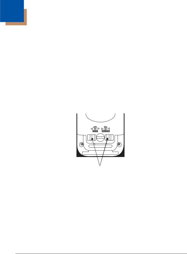
1.Unlock the battery door by turning the screw counterclockwise until the slot is upright.
Lock Releases
2.Push the lock releases toward the screw.
2 - 1

3.Insert the battery into the battery well with the contacts facing downward.
4.Replace the door with a hinging motion and turn the screw clockwise to lock the door.
Note: The battery door must be installed prior to booting the unit.
!We recommend use of Honeywell Li-Ion battery packs. Use of any non-Honeywell battery may result in damage not covered by the warranty.
2 - 2
Step 2. Charge the Batteries
Optimus 5900 RFID terminals ship with both the |
|
main battery pack and internal backup battery |
|
significantly discharged of power. Use the power |
|
supply cable to charge the main battery pack. The |
|
LED turns green (red while charging) when |
|
charging is complete. The average charge time for |
|
a fully depleted main battery is 7 hours. It takes |
1 |
less time if the battery has some charge. |
|
1. Attach the plug adapter to the plug of the power supply cable (if not already attached).*
2. Insert the plug into the appropriate power source.
3. Plug the Optimus 5900 RFID power supply |
2 |
|
cable into the DC Power Jack (see page 3-10) |
||
|
||
on the bottom end of the unit. |
|
|
Note: If you remove the battery pack or it completely |
3 |
|
discharges, there is a 30 minute window in which |
|
to insert a charged battery pack before the backup battery completely discharges. If your backup battery completely discharges, the contents of the RAM memory will be lost. If your backup battery is less than fully charged, there is a proportionally smaller window of time available.
LED Indicators
Red LED On |
Charging |
|
|
Green LED On |
Battery is fully charged |
|
|
*This power supply (charger) can also be used to power the Optimus 5900 RFID eBase Device (Model: 5900-EHB) (see page 9-1).
! We recommend use of Honeywell peripherals, power cables, and power adapters. Use of any nonHoneywell peripherals, cables, or power adapters may cause damage not covered by the warranty. DO NOT attempt to charge damp/wet mobile computers or batteries. All components must be dry before connecting to an external power source.
Step 3. Boot the Terminal
The terminal begins booting as soon as power is applied and runs by itself. Do NOT press any keys or interrupt the boot process.
When the boot process is complete, the Desktop appears, and the terminal is ready for use.
2 - 3
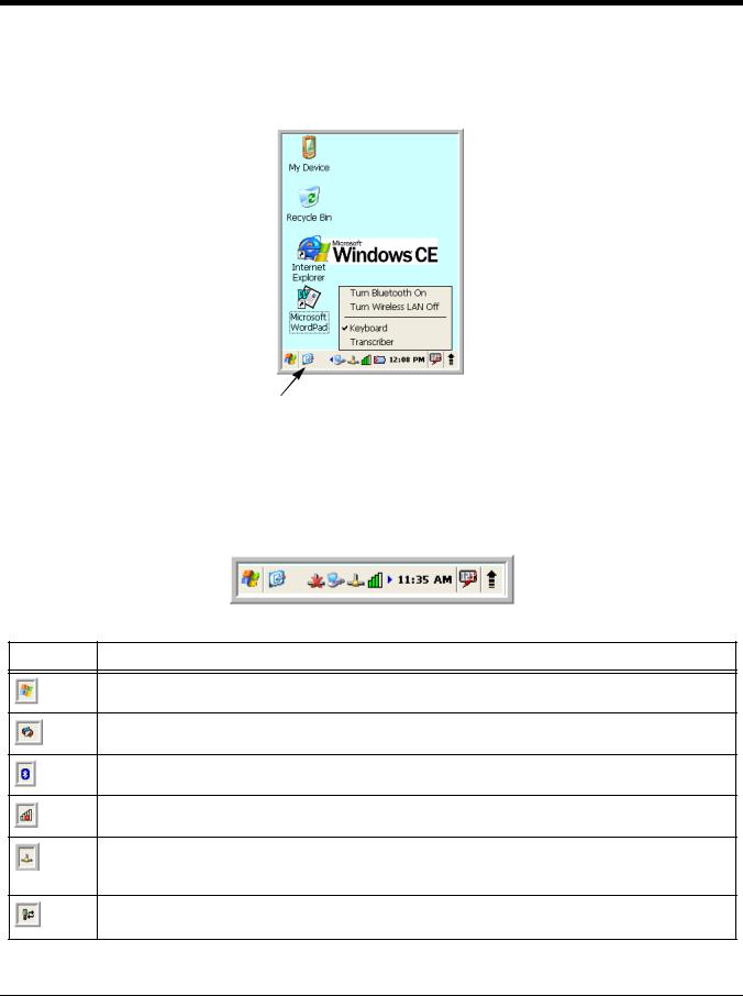
Desktop
Note: You can access the Desktop any time by tapping the Change Views icon in the command bar and selecting Desktop on the popup menu.
Tap to change views
Command Bar Icons
The command bar, located at the bottom of application screens, provides access to many system functions and programs. If there are more functions/programs that can display, select the left or right arrows to scroll through the additional icons.
Icon Meaning
Opens the Start menu.
Tap to change views between open applications or to return to the desktop.
Accesses the Bluetooth radio. Double tap this icon to open the Bluetooth Handler (see page 8-1).
Shows signal strength of WiFi radio. (A red X indicates it is not currently associated to an AP.)
Indicates Ethernet communications. When the terminal is undocked, no icon appears. When it is docked without a cable, the icon has a red X through it. When docked with a cable connected, this icon displays.
Indicates that the USB communication cable is connected. Double tap to display USB status window.
2 - 4
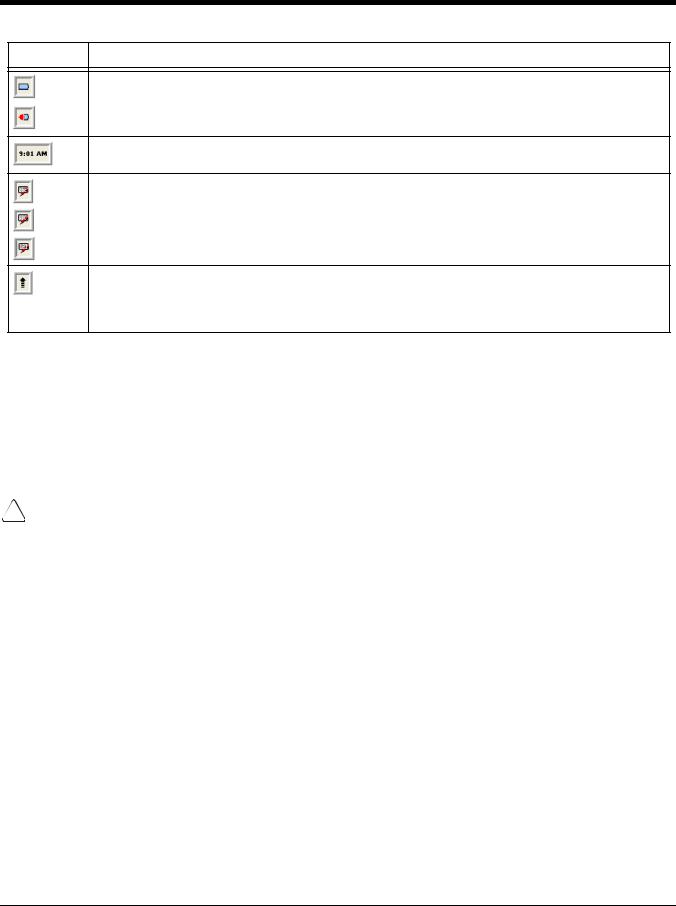
Icon Meaning
Indicates the status of battery power. Double tap to open the Power control panel setting.
When this icon shows a red power plug, it indicates the device is using external power.
Displays the current time. Double tap to change the time and date.
Indicates whether the keypad is standard alpha (uppercase and lowercase), all caps alpha, or in numeric mode. Press the ALPHA button on the keypad to switch modes.
The up arrow allows you to turn the Wireless LAN and Bluetooth connection on or off. It also allows you to toggle between the Keyboard and Transcriber. When Keyboard is selected, a keyboard is displayed so you can tap text and number keys. Transcriber recognizes handwriting and symbols entered using the stylus.
Using the Stylus
The terminal comes with a stylus inserted in the handle. Use this stylus (or your finger) to select or enter information on the touch screen. The stylus functions as a mouse; generally, a tap is the same as a click.
Tap |
Tap the touch screen once or double tap to open menu items and select options. |
Drag |
Hold the stylus on the screen and drag across the screen to select text and images. |
Tap & hold |
Tap and hold the stylus on an item and a pop-up menu appears. On the pop-up menu, tap |
|
the action of the task you want to perform. |
!Use of objects, such as paper clips, pencils, or ink pens on the touch screen can damage the input panel and may cause damage not covered by the warranty.
For more information about the touch screen, see Touch Screen Display on page 3-2.
2 - 5
Selecting Programs
Tap Start > Programs. To open a program, tap the icon on the menu.
Pop-Up Menus
You can quickly choose an action for an item using the pop-up menus.
1.Tap and hold the stylus on the item name. The pop-up menu appears.
2.Lift the stylus and tap the action you want to perform.
The contents of pop-up menus change according to the program you are using.
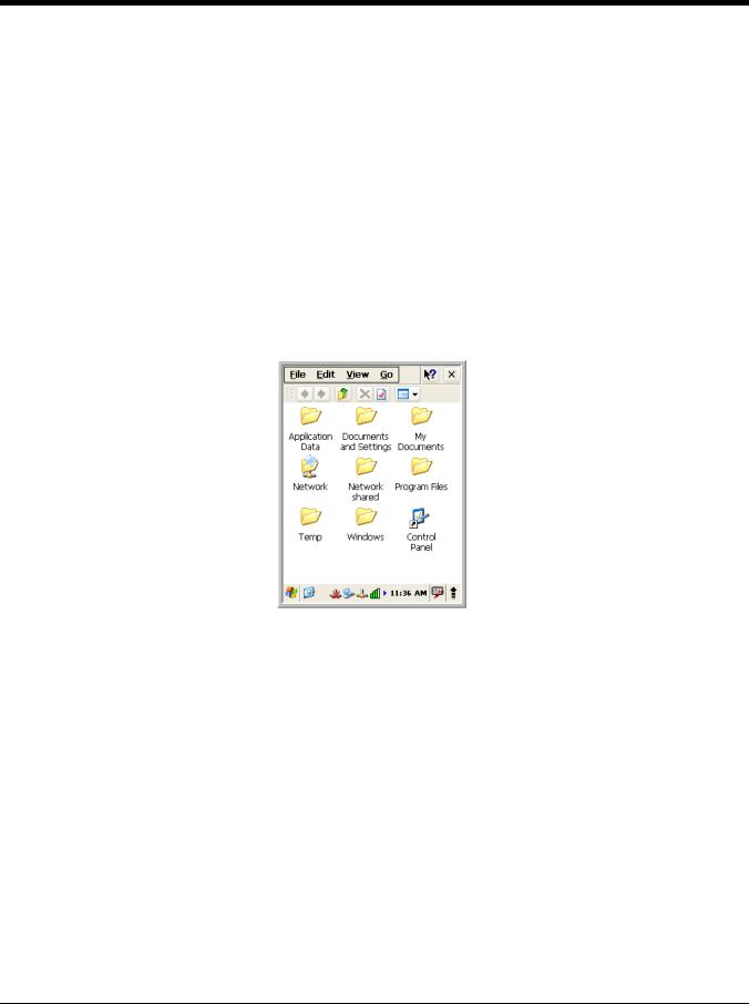
Using Windows Explorer
Use Windows Explorer to navigate through the files on your system. On the desktop, double tap the My Device icon and Windows Explorer opens to the root level.
Move files by tapping and holding on the file, then tapping Cut, Copy or Paste on the pop-up menus that appear.
2 - 6

3
Terminal Hardware Overview
Optimus 5900 RFID terminals include a number of standard terminal configurations as well as charging and communication peripherals and accessories to maximize the efficiency of your application setting.
Standard Terminal Configurations
There are two standard Optimus 5900 RFID configurations: WPAN only and WPAN/WLAN. Both configurations include the following options; however, the WPAN/WLAN configuration has both a Bluetooth radio and an 802.11g radio.
Optimus 5900 RFID WPAN and WPAN/WLAN
•Microsoft Windows CE 5.0 Professional
•Marvell PXA 300 624MHz
•128MB RAM X 256MB (non-volatile) Memory
•26-key numeric keypad (alpha shifted)
•3.5” TFT transmissive, 65k color LCD display with backlight, QVGA (240 x 320)
•Li-Ion battery: 3.7V / 5000mAh / 12.2 Wh
•5300SR image engine with laser aiming
•(WPAN) - Bluetooth radio
•(WPAN/WLAN) - Bluetooth and 802.11g radio
•Optimus power cable (included with each Optimus 5900 RFID terminal)
3 - 1

Front Panel Features
Scan/Decode LED
Touch Screen Display (screen protector installed at the factory)
Navigation Keys 


 Software Reset Key


 Power Key
Scan/Decode LED
The LED lights red when a scan fails.
The LED lights green when a scanned bar code is successfully decoded.
The LED lights red while the main battery is charging.
The LED lights green when the main battery charging is completed.
The LED lights blue when data is being downloaded.
Keypad
26-key numeric keypad (alpha shifted) (includes side scan buttons).
Microphone
The integrated microphone can be used for audio recording.
Touch Screen Display
The display is a 3.5” TFT transmissive, 65k color LCD display with a backlight, QVGA (240 x 320 resolution); see Display Backlight on page 3-3. The touch panel is a 4-wire analog resistive touch.
Optimus 5900 RFID terminals ship with a screen protector already installed over the
!screen protector before initial use. Honeywell recommends using screen protectors, especially for applications that require high volume interfacing with the touch screen. For
more information, see Using Screen Protectors on page 3-3. You can purchase additional screen protectors by contacting your Honeywell sales representative.touch screen lens to help prevent damage to the touch screen. Do NOT remove this
For touch screen input, use the stylus included with the terminal or your finger. The method you choose depends on which one is most appropriate for your application. While there is a great deal of variation in different applications, you generally achieve greater accuracy with the stylus for buttons or icons that are close together.
3 - 2

!Use of objects, such as paper clips, pencils, or ink pens on the touch screen can damage the input panel and may cause damage not covered by the warranty.
Display Backlight
The intensity of the backlight of the touch screen display may be changed, and the backlight may be programmed to turn off after the terminal has been idle for a specified period of time.
To adjust the intensity of the backlight while on battery power, tap Start > Settings > Control Panel > double tap Backlight.
Screen Backlight - Battery/External Power
Move the slider to adjust the screen backlight while on battery power.
You may turn the screen backlight off if the device is not used for a designated period of time by checking the option and designating the desired time period.
You may also turn on the screen backlight when a button is pressed or the screen is tapped by selecting the appropriate checkbox.
Note: Using the backlight option while on battery power substantially reduces battery life.
You may make the same changes when on external power by tapping the
External tab.
Keyboard Backlight
The intensity of the backlight of the keys on the keyboard may be changed and the backlight may be programmed to remain on for a specified period of time once a key is pressed.
To adjust the brightness of the keys, tap the Keyboard tab. Move the slider to adjust the backlight while on battery power.
To turn on the keyboard backlight, check the checkbox and change the duration of the backlight.
Using Screen Protectors
Honeywell defines proper use of the terminal touch panel display as using a screen protector and proper stylus. Screen protectors maintain the ongoing
integrity (i.e., prevent scratching) of the touch panel, which is why their use is recommended for applications that require a high to medium level of interface with the touch panel.
Honeywell continues to advocate the use of screen protectors on all Optimus 5900 RFID terminals. We recommend implementing a screen protector replacement program to ensure that screen protectors are replaced periodically when signs of damage/wear are noticeable. For general use, we recommend replacing the screen protector every thirty (30) days. However, replacement cycles vary according to the average level of touch panel use in your application.
Replacement screen protectors can be purchased directly from Honeywell. Contact a Honeywell sales representative for details.
Honeywell also mandates use of a proper stylus, which is one that has a stylus tip radius of no less than 0.8mm. Use of the Honeywell stylus included with the terminal is recommended at all times.
3 - 3

Honeywell’s warranty policy covers wear on the touch panel for the first 12 months provided that a screen protector is applied and an approved stylus is used for the 12-month duration covered by the warranty.
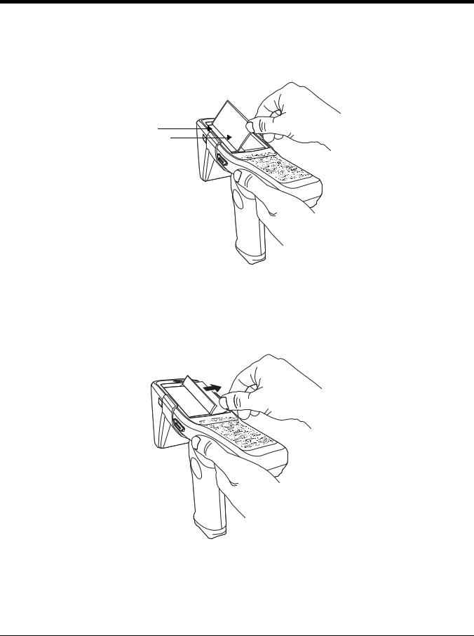
Removing the Screen Protector
Optimus 5900 RFID terminals ship with a touch screen protector already installed. To replace the screen protector, you must remove the one already installed.
1.Press the red Power button to suspend the unit.
2.Using a strong, flat, plastic card (e.g., credit card) wedge the edge of the card under the existing screen protector. Catch the edge of the screen protector and pull it up and away from the touch panel.
Note: If you have one, you can also use the small plastic squeegees designed for touch panels.
3.Wipe the screen with a clean, non-abrasive, lint-free cloth.
Note: Use ionized air, if available, to blow additional dirt or particles off the touch panel.
Installing Your Screen Protector
When installing a new screen protector, use a flat plastic card (e.g., credit card) to apply the screen protector smoothly and remove any air bubbles.
Note: If you have one, you can also use the small plastic squeegees designed for touch panels.
1.Press the orange Power button to put the terminal in Suspend Mode.
2.Clean the touch panel thoroughly with a clean, non-abrasive, lint-free cloth. Make sure nothing is on the touch panel.
3 - 4
3.Release the left edge of the backing paper on the screen protector and align the exposed edge of the screen protector along the left edge of the touch panel. Make sure that it lies flush with edges of the touch panel
Backing
Paper
Screen Protector
Note: To reposition the screen protector, lift up gently and reapply.
4.Pull smoothly and evenly from left to right until the screen protector is applied. Press gently but firmly. Use the card as necessary to smooth out any air pockets or bumps after application.
3 - 5

5.Press the Power key to wake the terminal and check the touch panel with the stylus.
6.Verify that the screen accepts input from the stylus as usual. If not, re-apply the screen protector.
7.Press the orange Power button to put the terminal back in Suspend Mode.
8.Clean the surface of the screen protector with a clean, non-abrasive, lint-free cloth.
9.Press the Power key to wake the terminal again.
10.For maximum performance, recalibrate the screen. Tap Start > Settings > Control Panel > double tap Stylus > Calibration tab.
3 - 6
11. Tap Recalibrate and follow the instructions on the screen.
Back Panel Features
Image Engine Window 
Speaker
Battery Well 

Battery Well
For information about installing the battery, see Changing the Main Battery Pack on page 3-12. For information about battery power, see Battery Power on page 3-11.
Speaker
The integrated speaker sounds audio signals as you scan bar code s and enter data, but emits no ambient noise on system activity (i.e., processor, memory access, radio traffic, etc.). The speaker can also be used for playing sounds (e.g., WAV or MP3 files).
The speaker meets the following SPL levels at 40cm:
•500Hz–67db
•1KHz–72db
•4KHz–72db
3 - 7
 Loading...