


BWTM RigRat
Local Area Gas Monitor
User’s Guide
Rev. A
March 2020
P/N W03-4001-000
Product Registration
Register your product online by visiting: https://www.honeywellanalytics.com/en/support/product-registration
IMPORTANT! BUMP TEST THE MONITOR
Prior to use, every gas detection monitor should be bump tested to confirm the response of all sensors and activation of all alarms by exposing the monitor to a concentration of target gas that exceeds the low alarm set point. A bump test is also recommended if the monitor has been subjected to physical impact, liquid immersion, an Over Limit alarm event, or custody changes, or anytime the monitor’s performance is in doubt.
To ensure greatest accuracy and safety, only bump test and calibrate in a fresh air environment.
The monitor should be calibrated every time it does not pass a bump test, but no less frequently than every six months, depending on use and exposure to gas and contamination, and its operational mode.
•Calibration intervals and bump test procedures may vary due to national legislation.
•Honeywell recommends using calibration gas cylinders containing the gas that is appropriate to the sensor you are using, and in the correct concentration.
© 2020 Honeywell International

|
BW RigRat User’s Guide |
|
Contents |
|
|
1. Standard Contents .................................................................................................... |
10 |
|
2. General Information................................................................................................... |
11 |
|
Certification ...................................................................................................... |
11 |
|
General ............................................................................................................ |
11 |
|
Wireless module Configuration......................................................................... |
12 |
|
Sensor configuration ........................................................................................ |
12 |
|
Electrical parameters........................................................................................ |
13 |
|
Type Designation ............................................................................................. |
13 |
|
3. User Interface............................................................................................................ |
16 |
|
Display Overview ............................................................................................. |
16 |
|
3.1.1. |
Status Indicator Icons ............................................................................... |
16 |
3.1.2. Icon Arrangement ........................................................................................ |
18 |
|
3.1.3. |
Design & Interface .................................................................................... |
21 |
3.1.4. |
Rain Protector (Optional) .......................................................................... |
22 |
Screen Display For Various Numbers Of Active Sensors ................................. |
22 |
|
Info |
................................................................................................................... |
23 |
4. Mesh Wireless Control And Submenus ..................................................................... |
24 |
|
Mesh ..............................................................Wireless Network (if supported) |
24 |
|
4.1.1. Closed ..................................................................................-Loop Network |
24 |
|
4.1.2. Connect ..................................................................................To Controller |
25 |
|
4.1.3. Connect ........................................................................To Radiant Reader |
26 |
|
5. BLE ........................................................................................................................... |
|
27 |
BLE ......................................................................................................Pairing |
27 |
|
Broken ...................................................................................BLE Connection |
28 |
|
Wi-Fi ........................................................................Connection (if supported) |
28 |
|
5.3.1 Secure ................................................Wireless Access Point Configuration |
28 |
|
5.3.2 Setting ..........Wi-Fi Communication Parameters in Device Configurator app |
29 |
|
Secure ......................................................................Wireless Communication |
31 |
|
6. Battery Charging ....................................................................................................... |
32 |
|
Charging .................................................................................................Ports |
32 |
|
6.1.1. ...........................................................................AC Charging, Safe Area |
32 |
|
6.1.2. ......................Intrinsically Safe Runtime Extension For Hazardous Areas |
33 |
|
6.1.3. ..................................................................Cover Ports When Not In Use |
35 |
|
Battery ...................................................................................................States |
36 |
|
7. Wired Communication ............................................................................................... |
37 |
|
Serial ...........................(Not Intended To Be Used In Explosive Atmospheres) |
37 |
|
Switch .............................................................................................................. |
38 |
|
4-20mA ........................................................................................................IN |
40 |
|
Cover .................................................Communication Ports When Not In Use |
41 |
|
8. External Filter ............................................................................................................ |
41 |
|
Filter ...........................................................................Replacement (Pumped) |
41 |
|
Filter ..........................................................................Replacement (Diffusion) |
43 |
|
9. Turning The ................................................................................RigRat On And Off |
45 |
|
Turning ....................................................................................The RigRat On |
45 |
|
Turning ....................................................................................The RigRat Off |
46 |
|
Testing ...................................................................................Alarm Indicators |
47 |
|
10. Modes of .................................................................................................Operation |
48 |
|
Menu ......................................................................................................Mode |
48 |
|
10.2.1. ..................................................................................Entering Menu Mode |
48 |
|

|
BW RigRat User’s Guide |
|
|
10.2.2. Exiting Menu Mode .................................................................................... |
49 |
|
Diagnostic Mode .............................................................................................. |
49 |
|
Enter Diagnostic Mode ..................................................................................... |
49 |
|
10.4.1. Navigating Diagnostic Mode ...................................................................... |
49 |
|
Exit Diagnostic Mode........................................................................................ |
50 |
11. Programming........................................................................................................... |
51 |
|
|
Using Device Configurator................................................................................ |
51 |
|
Security Mode .................................................................................................. |
51 |
12. |
Calibration And Testing ........................................................................................... |
52 |
|
Bump Testing And Calibration.......................................................................... |
52 |
|
Bump (Functional) Testing ............................................................................... |
52 |
|
Calibration........................................................................................................ |
54 |
13. |
Maintenance............................................................................................................ |
55 |
|
Cleaning........................................................................................................... |
55 |
|
Antenna Installation.......................................................................................... |
55 |
14. |
RAEMet Sensor Installation (not intended to be used in |
|
|
explosive atmospheres).......................................................................................... |
60 |
15. |
Alarms Overview ..................................................................................................... |
62 |
|
Alarm Signals................................................................................................... |
62 |
|
Alarm Signal Summary..................................................................................... |
62 |
|
Manual Alarms Test ......................................................................................... |
63 |
16. |
Troubleshooting....................................................................................................... |
65 |
17. |
Editing Features ...................................................................................................... |
67 |
|
Error Codes...................................................................................................... |
68 |
18. |
Specifications .......................................................................................................... |
71 |

BW RigRat User’s Guide
WARNINGS
This Manual must be carefully read by all individuals who have or will have the responsibility of using, maintaining, or servicing this product. The product will perform as designed only if it is used, maintained, and serviced in accordance with the manufacturer’s instructions. The user should understand how to set the correct parameters and interpret the obtained results.
CAUTION!
Only use the Honeywell-specified rechargeable lithium-ion battery pack supplied with the instrument.
Charge the instrument Li-ion battery using the specifically supplied charger and only outside hazardous areas. The maximum voltage from the AC charger Um must not exceed 6.0 VDC.
The battery pack can only be changed in a non-hazardous area. Only use approved rechargeable battery pack P/N 500-0165-000 produced by Honeywell.
Any data download device connected to this instrument must be approved SELV or Class 2 equipment.
Use of non-Honeywell components will void the warranty and can compromise the safe performance of this product.
Warning: Substitution of components may impair safe performance of this product.
When changing the sensor configuration, ensure the operator is aware of any changes to certification restrictions
SPECIAL CONDITIONS FOR SAFE USE
This multi-gas monitor must be calibrated if it does not pass a bump test, when a new sensor has been installed, or at least once every 180 days, depending on use and sensor exposure to poisons and contaminants
The AC charger system of BW RigRat shall only be applied in non-hazardous areas by charger specifically supplied for use with the unit (for example model number ADS-25SGP-06 05717E, manufactured by HONOR Electric), approved as SELV or Class 2 equipment against IEC 60950 or an equivalent IEC standard. The maximum voltage Um from the charger shall not exceed DC 6.0V.
The BW RigRat enclosure has an ingress protection of rating of IP-54. The user shall ensure that the external plugs that used for IS charger, 4-20mA input, and ON-OFF switch will provide a degree of protection of IP-54, after they are connected to the sockets.
Do not open when an explosive atmosphere is present.
Note: Users are recommended to refer to ISA -RP12.13, Part II-1987 for general information on installation, operation, and maintenance of combustible gas detection instruments.
5

BW RigRat User’s Guide
WARNINGS
ONLY THE COMBUSTIBLE GAS DETECTION PORTION OF THIS INSTRUMENT HAS BEEN ASSESSED FOR PERFORMANCE.
UNIQUMENT, LA PORTION POUR DÉTECTOR LES GAZ COMBUSTIBLES DE CET INSTRUMENT A ÉTÉ ÉVALUÉE.
CAUTION: BEFORE EACH USE, SENSITIVITY OF THE COMBUSTIBLE GAS SENSOR MUST BE TESTED ON A KNOWN CONCENTRATION OF METHANE GAS EQUIVALENT TO 20 TO 50% OF FULL-SCALE CONCENTRATION. ACCURACY MUST BE WITHIN 0 AND +20% OF ACTUAL.
ACCURACY MAY BE CORRECTED BY CALIBRATION PROCEDURE.
ATTENTION: AVANT CHAQUE UTILISATION VERIFIER LA SENSIBILITE AVEC UNE CONCENTRATION CONNUE DE METHANE EQUIVALENTE A 20 to 50% DE LA PLEINE ECHELLE. LA PRECISION DOIT ETRE COMPRISE ENTRE 0 to 20% DE LA VALEUR VRAIE ET PEUT ETRE CORRIGEE PARUNE PROCEDURE D’ETALONNAGE.
CAUTION: HIGH OFF-SCALE READINGS MAY INDICATE AN EXPLOSIVE CONCENTRATION.
ATTENTION: DES LECTURES SUPÉRIEURES A L’ÉCHELLE PEUVENT INDIQUER DES
CONCENTRATIONS EXPLOSIVES.
6
BW RigRat User’s Guide
FCC Compliance Statement:
This device complies with part 15 of the FCC Rules. Operation is subject to the following two conditions: (1) This device may not cause harmful interference, and (2) this device must accept any interference received, including interference that may cause undesired operation.
Warning: Any changes or modifications to this unit not expressly approved by the party responsible for compliance could void the user's authority to operate the equipment.
Class A device:
NOTE: This equipment has been tested and found to comply with the limits for a Class A digital device, pursuant to part 15 of the FCC Rules. These limits are designed to provide reasonable protection against harmful interference when the equipment is operated in a commercial environment. This equipment generates, uses, and can radiate radio frequency energy and, if not installed and used in accordance with the instruction manual, may cause harmful interference to radio communications. Operation of this equipment in a residential area is likely to cause harmful interference in which case the user will be required to correct the interference at his own expense.
MPE caution (if a FCC certified RF module is inserted in & the separation distance is indicated in the FCC grant of RF module)
To satisfy FCC / IC RF exposure requirements, a separation distance of 20 cm or more should be maintained between the antenna of this device and persons during device operation.
To ensure compliance, operations at closer than this distance is not recommended.
This device contains license-exempt transmitter(s)/receiver(s) that comply with Innovation, Science and Economic Development Canada’s license-exempt RSS(s). Operation is subject to the following two conditions:
(1)This device may not cause interference.
(2)This device must accept any interference, including interference that may cause undesired operation of the device.
L’émetteur/récepteur exempt de licence contenu dans le présent appareil est conforme aux CNR d’Innovation, Sciences et Développement économique Canada applicables aux appareils radio exempts de licence. L’exploitation est autorisée aux deux conditions suivantes:
1)L’appareil ne doit pas produire de brouillage;
2)L’appareil doit accepter tout brouillage radioélectrique subi, même si le brouillage est susceptible d’en compromettre le fonctionnement.
7
BW RigRat User’s Guide
Warning: Substitution of components may impact intrinsic safety.
Avertissement: La substitution de composants peut compromettre la securité intrinsèque.
WARNING: Read and understand instruction manual before operation or servicing.
AVERTISSEMENT: Lisez et comprenez le manual d’instructions avant d’utiliser ou service.
WARNING: Substitution of components may impact intrinsic safety.
AVERTISSEMENT: La substitution de composants peut compromettre la sécurité intrinsèque. WARNING: To prevent ignition of a hazardous atmosphere, batteries must only be charged in an area known to be non-hazardous. Um = 6.0V. Use only approved charger.
AVERTISSEMENT: Afin de prevenir l’inflammation d’atmosphères dangereuse, ne charger le jeu de batteries que dans des emplacement designés non dangereux. Um = 6V Utilisez uniquement un chargeur approuvé.
Only charge the battery in safe area in the ambient temperature range 0°C ≤ Tamb ≤ 40°C.
8

BW RigRat User’s Guide
Proper Product Disposal At End Of Life
EU Directive 2012/19/EU: Waste Electrical and Electronic Equipment (WEEE)
This symbol indicates that the product must not be disposed of as general industrial or domestic waste. This product should be disposed of through suitable WEEE disposal facilities. For more information about disposal of this product, contact your local authority, distributor, or the manufacturer.
Sensor Specifications, Cross-Sensitivities, And Calibration Information
For information on sensor specifications, cross-sensitivities, and calibration information, refer to Technical Note TN-114: Sensor Specifications And Cross-Sensitivities. All specifications presented in this Technical Note reflect the performance of standalone sensors. Actual sensor characteristics may differ when the sensor is installed in different instruments. As sensor performance may change over time, specifications provided are for brand-new sensors.
Make Sure Firmware Is Up To Date
For best operation, make sure your monitor is running the latest firmware.
9
BW RigRat User’s Guide
1. Standard Contents
The RigRat is available in various user-specified configurations, each with the accessories shown below.
In addition to the instrument, the following are included:
Item |
Part Number |
|
|
AC adapter |
W03-3044-000 |
|
|
LCD Cover |
W03-2129-000 |
|
|
Diffusion calibration cap assembly* |
W03-3013-000 |
|
|
Pump calibration tube assembly* |
W03-3020-000 |
|
|
External Filter (Pumped version only) |
W03-3006-000 |
|
|
QuickStart Guide |
W03-4002-000 |
|
|
Antenna 868-928MHz, RP-N** |
550-7056-000 |
|
|
Antenna 2.4GHz, RP-N** |
550-7057-000 |
|
|
*Depends on whether the model is pumped or diffusion.
**Depends on wireless modem (if installed).
10
BW RigRat User’s Guide
2. General Information
 Certification
Ex ia II C/ II B T4 Ga
Ex da ia II C/ II B T4 Ga
Ex db ia II C/ II B T4 Gb
II 1G Ex ia C/ B T4 G
II 1G Ex da ia C/ B T4 Ga
II 2G Ex db ia C/ B T4 Gb
Refer to following contents to find more information about Ex marking and permissible ambient temperature.
This apparatus is designed to be in accordance with the following Standards: IEC60079-0:2017 Explosive atmospheres—Part 0: Equipment—General requirements;
IEC60079-11:2011 Explosive atmospheres -Part 11: Equipment protection by intrinsic safety “i”.
EN IEC60079-0:2018 Explosive atmospheres—Part 0: Equipment—General requirements;
EN 60079-11:2012 Explosive atmospheres -Part 11: Equipment protection by intrinsic safety “i”.
Refer to following contents to find more information about Ex marking and permissible ambient temperature.
 General
The BW RigRat Local Area Gas Monitor (hereinafter called “RigRat”) as a transportable equipment, fills the gap between portable personal detectors and fixed-infrastructure fire and gas systems. Its primary function is to alert personnel of a gas leak in their proximity, it can provide continuous measurement of gas concentrations.
The RigRat’s main use is in temporary zone monitoring, such as repair, fence line, and inert applications where there is a possibility of a gas release.
The overall dimensions of the RigRat are about 396mm x 288mm x 470mm (15.6” x 11.4” x 18.5”), it consists of an enclosure, 2 rechargeable battery packs (P/N 500-0165-000) as main power, 1 Li-ion rechargeable cell (P/N MS-621T) for RTC power, 1 LCD display, 4 LED indicators for light alarm, 2 buzzers for the audible alarm, 1 multi-function button, and printed circuit-board assemblies. In addition, it may also be optionally equipped with a gas-intake pump, up to 6 kinds of wireless modules in 4 wireless module slots, and up to 5 kinds of sensors in 6 sensor slots.
An AC charger connector is provided to charge battery packs in a non-hazardous area. Refer to “Specific Conditions of Use” for more information. An IS charger connector is used to connect through a safety barrier to charge one of the battery packs in hazardous areas, likewise providing the intrinsically safe power to the product.
The RigRat is transportable and does not require grounding (earthing). However, the circuits and the metal parts of the enclosure can still withstand a 500V dielectric test with a leakage current no more than 5mA.
11

BW RigRat User’s Guide
 Wireless module Configuration
Depending on the configuration, the RigRat may provide GPS, GNSS, Mesh, WIFI, BLE, LoRa, and/or NB-IoT wireless communication, the possible configurations are shown in this table:
Designator on PCB |
|
U19 |
J7 |
J9 |
J8 |
BLE |
|
● |
|
|
|
either WIFI or NB-IoT |
|
|
|
● |
|
either Mesh or LoRa |
|
|
● |
|
|
either GPS or GNNS |
|
|
|
|
● |
● Optional wireless module |
|
|
|
|
|
 Sensor configuration
The RigRat may be configured with a MIPEX NDIR sensor, Dynament NDIR sensor, LEL sensor, PID sensor, and EC sensor, which are mounted inside the IP-54 RigRat enclosure. These sensors have been separately certified or tested according to IEC 60079. Refer to this table for more information about these sensors:
Sensor |
Type |
Ex marking |
IECEx CoC or |
Ambient |
Standard |
|
|
|
|
ExTR |
temperature |
|
|
|
|
|
|
( ) |
|
|
|
|
|
|
|
IEC60079-0:2007 |
|
|
|
|
|
|
Edition5 |
|
EC |
4R+EC |
Ex ia II C T4 Ga |
GB/SIR/ExTR10. |
-20 to+55 |
IEC60079-11:2006 |
|
0276/00 |
Edition5 |
|||||
|
|
|
|
|||
|
|
|
|
|
IEC60079-26:2006 |
|
|
|
|
|
|
Edition2 |
|
|
|
Ex ia C Ga |
IECEx ITS |
|
IEC60079-0:2011 |
|
|
MIPEX 02 |
11.0047U |
|
Edition:6.0 |
||
MIPEX NDIR |
II 1G Ex ia IIC Ga |
Issue No.5 |
-55 to+60 |
|||
series |
IEC 60079-11:2011 |
|||||
|
|
ITS11ATEX274 |
|
|||
|
|
|
|
Edition:6.0 |
||
|
|
|
18U, isse5 |
|
||
|
|
|
|
|
IEC60079-0:2011 |
|
|
|
|
IECEx FTZU |
|
Edition:6.0 |
|
Dynament |
MSH2ia |
Ex db C Gb |
15.0002U Issue |
|
IEC60079-1:2014-06 |
|
No.2 |
-20 to+60 |
|||||
NDIR |
*** |
II 2 G Exdb IIC Gb |
Edition:7.0 |
|||
FTZU 14 ATEX |
|
|||||
|
|
|
|
IEC60079-11:2011 |
||
|
|
|
0213U |
|
||
|
|
|
|
|
Edition:6.0 |
|
|
|
|
|
|
IEC60079-0:2007 |
|
|
|
|
|
|
Edition5 |
|
PID |
4R+PID |
Ex ia II C T4 Ga |
GB/SIR/ExTR10. |
-20 to+55 |
IEC60079-11:2006 |
|
0203/00 |
Edition 5 |
|||||
|
|
|
|
|||
|
|
|
|
|
IEC60079-26:2006 |
|
|
|
|
|
|
Edition2 |
|
|
|
|
IECEx ULD |
|
IEC60079-0:2011 |
|
|
|
|
|
Edition6 |
||
|
|
Ex da ia C Ga |
16.0016U Issue |
|
||
LEL Sensor |
1 LEL 75 |
|
IEC60079-1:2014-06 |
|||
No.1 |
|
|||||
II 1G Ex da ia IIC |
-40 to+60 |
|||||
(Group II, T4) |
x |
DEMKO 16 |
Edition7 |
|||
Ga |
|
|||||
|
|
ATEX 1557U |
|
IEC60079-11:2011 |
||
|
|
|
|
|||
|
|
|
Rev.2 |
|
||
|
|
|
|
Edition6 |
||
|
|
|
|
|
12
BW RigRat User’s Guide
For possible sensor installation, refer to thhis table:
|
Slot 1 |
Slot 2 |
Slot 3 |
Slot 4 |
Slot 5 |
Slot 6 |
MIPEX NDIR Sensor |
● |
|
|
|
|
|
Dynament NDIR Sensor |
● |
● |
|
● |
|
|
PID Sensor |
|
● |
|
|
|
|
LEL Sensor |
|
|
● |
|
|
|
EC Sensor |
|
● |
● |
● |
● |
● |
● Sensor locations
EC Sensor: Max.5pcs
MIPEX NDIR Sensor: Max.1pc PID Sensor: Max.1pc
LEL Sensor: Max.1pc
Dynament NDIR Sensor: Max.3pcs
In addition, there is a noise sensor located inside of the RigRat, which can measure the ambient noise. The RigRat also contains a THP sensor in pumped version that can measure the ambient temperature, humidity, and gas flow outside.
 Electrical parameters
The RigRat provides 5 external connectors with the following electrical parameters:
AC charger connector(use only in a non-hazardous area): Um=6V
IS charger connector: Ui=24V, Ii=150mA, Pi=1.15W, Ci=88.4nF, Li=0.013mH
ON-OFF switch connector: Ui=30V, Ii=100mA, Pi=0.75W, Ci=0, Li=0
4~20mA input connector: Ui=30V, Ii=100mA, Pi=0.75W, Ci=0, Li=0
 Type Designation
BWRR100 a-b-c
a identifies product version: D, P
D: Diffusion version (without pump) P: Pump version
b identifies sensor configuration with regard to PID, Dynament NDIR, and LEL sensor
0:Without PID, Dynament NDIR, or LEL sensor
1:With PID sensor
2:With Dynament NDIR sensor
3:With LEL sensor
4:With PID and Dynament NDIR sensor
5:With Dynament NDIR and LEL sensor
6:With LEL and PID sensor
7:With PID, Dynament NDIR, and LEL sensor
cidentifies wireless modules configuration with regard to WIFI and NB-IoT
0:Without WIFI or NB-IoT
1:With WIFI
2:With NB-IoT
3:Fitted with WIFI and NB-IoT
Depending on different configurations, the RigRat may refer to different types of protection, gas groups, and ambient temperatures, which are specified as below. The onerous restriction shall be taken into consideration in case one of the following is applied.
13
BW RigRat User’s Guide
1.The first digit designates the Diffusion/Pump version. The following table details the Diffusion/pump version together with ambient temperatures.
Type |
Version |
Ambient Temperature |
|
|
( ) |
BWRR100 D-b-c |
Diffusion version (without pump) |
-40 to+60 |
BWRR100 P-b-c |
Pump version |
-20 to+60 |
14

BW RigRat User’s Guide
2.The second digit designates the configuration of sensors with regard to PID, Dynament NDIR, and LEL sensor. The following table details the sensor configurations together with their Ex markings and ambient temperatures:
Type |
Sensor Configuration |
Ex Marking |
Ambient |
|
|
|
|
Temperature ( ) |
|
BWRR100 a-0-c |
without PID, Dynament |
Ex ia II C T4 Ga |
-40 to+60 |
|
NDIR or LEL |
||||
|
|
|
||
BWRR100 a-1-c |
with PID |
Ex ia II C T4 Ga |
-20 to +55 |
|
|
|
|
|
|
BWRR100 a-2-c |
with Dynament NDIR |
Ex db ia II C T4 Gb |
-20 to +60 |
|
|
|
|
|
|
BWRR100 a-3-c |
with LEL |
Ex da ia II C T4 Ga |
-40 to +60 |
|
|
|
|
|
|
BWRR100 a-4-c |
with PID and Dynament |
Ex db ia II C T4 Gb |
-20 to +55 |
|
NDIR |
||||
|
|
|
||
BWRR100 a-5-c |
with Dynament NDIR |
Ex db ia II C T4 Gb |
-20 to +60 |
|
and LEL |
||||
|
|
|
||
BWRR100 a-6-c |
with LEL and PID |
Ex da ia II C T4 Ga |
-20 to +55 |
|
|
|
|
|
|
BWRR100 a-7-c |
with PID, Dynament |
Ex db ia II C T4 Gb |
-20 to +55 |
|
NDIR and LEL |
||||
|
|
|
3.The third digit designates the configuration of wireless modules with regard to WIFI and NB-IoT. The following table details the wireless module configurations together with their gas groups.
Type |
Wireless Module |
Gas Group |
|
Configuration |
|
BWRR100 a-b-0 |
without WIFI or NB-IoT |
II C |
|
|
|
BWRR100 a-b-1 |
with WIFI |
II B |
|
|
|
BWRR100 a-b-2 |
with NB-IoT |
II B |
|
|
|
BWRR100 a-b-3 |
with WIFI and NB-IoT |
II B |
 Key Features
Available pumped or diffusion
Up to 6 gas sensor slots
Supports BLE/ Mesh/Wi-Fi/ GPS/LoRa (pending)
>25days’ runtime (Low Power version)
Wide operating temperature range (-40 to 60° C)
Rugged mechanical design
15
BW RigRat User’s Guide
3. User Interface
The user interface consists of the display, LEDs, an alarm buzzer, and one multi-function button.
 Display Overview
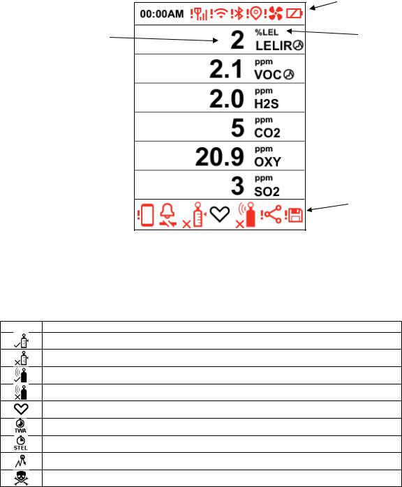
The backlit display provides visual feedback that includes the sensor types, readings, battery condition, and other functions.
Communication, Pump (if installed), and battery status
Reading value |
Unit of measure |
 Correction Factor indicator
 Sensor type
Alerts
3.1.1. Status Indicator Icons
Status indicators tell you whether a function is operating and/or its strength or level, as well as alerts.
Icon Function
Calibration passed
Calibration failed or overdue
Bump test passed
Bump failed or overdue
Status
TWA Alarm
STEL Alarm
Peak
Gas Alarm
16

BW RigRat User’s Guide
Inert Mode Enabled
!Pump failure Stealth/Mute
Button Press
Button Press And Hold
Mesh Wireless Signal Strength Mesh Wireless Failed
Mesh Network Is Configured
Mesh Network Failure/Lost Connection Closed-Loop Network Is Configured Closed-Loop Network Failure/Lost Connection
Wi-Fi Connected (shows connection strength) Wi-Fi Failure
BLE Enabled BLE Failure
GPS
GPS Failure
Correction Factor
Battery (1 bar ≥ 10% remaining, 2 bars ≥ 50%, 3 bars ≥ 80%)
Battery error
Device Configurator app (shows when a new file is being pushed to RigRat) Paired with Device Configurator app (flashes when data is transferring) Device Configurator app failure
Data Logging
17
BW RigRat User’s Guide
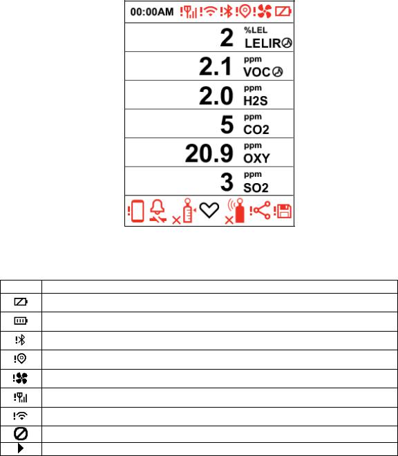
3.1.2. Icon Arrangement
Status and other information icons are shown at different places on the screen: The top, the “body”
(main display), and bottom.
Here is how they are organized and located on the screen:
Top
Icon Explanation
Battery Alarm
Battery Level
Bluetooth
GPS
Pump
Signal
Wi-Fi
Menu - Disabled
Menu – Disable Sensor Selected
18
BW RigRat User’s Guide
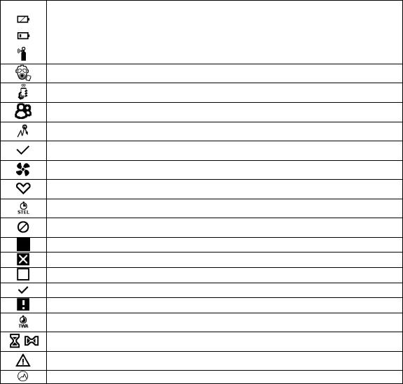
Body
Icon |
Explanation |
|
Battery Alarm |
|
|
|
Low Battery |
|
|
|
Bump Test |
Inert Mode
Mobile
Network
Peak
Positive
Pump
Status
STEL
Stop
Test Detect
Test Fail
Gas Not Detected During Test
Test Positive
Test Warning
TWA
Waiting For Operation To Complete (animated)
Warning!
Correction Factor Applied
19

BW RigRat User’s Guide
Data Readings
Icon |
Explanation |
|
Disabled |
|
|
|
High |
|
|
|
Low |
|
|
|
Sensor Disabled |
|
|
|
Peak |
|
|
|
STEL |
|
|
|
TWA |
|
|
Bottom |
|
|
|
Icon |
Explanation |
|
Alarm |
|
|
|
Bump Test Fail |
|
|
|
Bump Test Pass |
|
|
|
Calibration Fail |
|
|
|
Calibration Pass |
|
|
|
Click |
|
|
|
Hold |
|
|
|
Mesh Network |
|
|
|
Network |
|
|
|
Pair Device |
|
|
|
Status |
|
|
|
Stealth Mode |
|
|
|
Inert Mode |
|
|
|
Data Logging |
|
|
|
I/O in normal status |
|
|
|
I/O in alarm or fault status |
|
|
20
BW RigRat User’s Guide
3.1.3. Design & Interface
The RigRat’s functions are controlled via the front-panel multi-function button. The display shows information such as monitored threats, real-time readings and measurement units, alarm type (when in alarm, including cal. overdue), battery status, datalog (if on), and radio and connection quality (if available).
Front View
Noise
Sensor
Alarm
LED 
Display
Multi-Function 
Button
AC Charge
Port
Rear View |
Antenna |
|
|
|
Handle |
Alarm
LED
Sensor
Compartment
Antenna
 Handle
Alarm
LED
Alarm
Buzzer
IS Charge
Port
Alarm
LED
Gas Inlet
 (Pumped Version)
Alarm
Buzzer
|
|
4-20mA In |
Serial I/O |
I/O Connector |
Connector |
Connector |
Switch |
Port |
Port |
Port |
|
(Not intended to be |
|
|
used in explosive |
|
|
atmospheres |
|
|
In addition to turning the instrument on and off, the multi-function button can be used to control different parameters and make selections within the instrument’s menus. Also, pressing the button activates display backlighting when it is off: Press the button once when the backlighting is off to turn it on.
21
BW RigRat User’s Guide
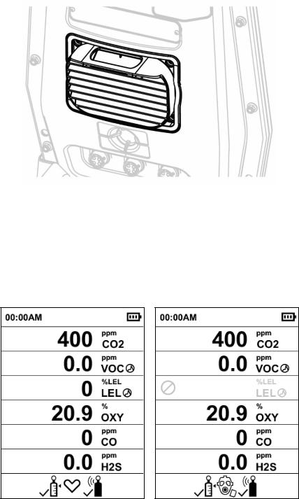
3.1.4. Rain Protector (Optional)
The optional Rain Protector (P/N: W03-2038-000) presses into place over the sensor compartment. It protects the sensors from rain and large debris. It easily pulls off when you need to access the sensor compartment.
 Screen Display For Various Numbers Of Active Sensors
The BW RigRat can accommodate from one to six sensors. When one or more sensors is either not installed or turned off, the display only shows the installed, active sensors. If one is turned off, it is shown in gray.
22
BW RigRat User’s Guide
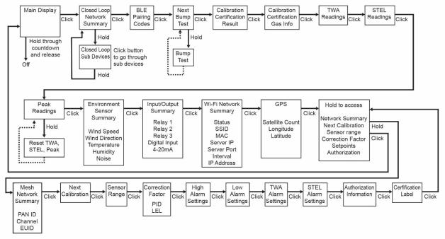
 Info
Info
The info screens are easy to step through by pressing the button once to advance from one to the next. Hold the button down for secondary actions.
Note: In most cases, if no buttons are pressed at any of the menu steps for 60 seconds, the instrument reverts to the main display.
23
 Loading...