


The Aquatrol 2000 controller is the central component for a single zone low pressure hot water heating system. It provides self adaptive heating curve, optimum start/stop operation, sequence control of two boilers, outside air compensated mixed water control using a 3-port motorised valve and pump, and domestic hot water control using a valve and/or pump.
A wide range of compatible sensors, a remote unit, valves and actuators complement the control system.
AQ2000
OPTIMISER/COMPENSATOR CONTROLLER
PRODUCT DATA
FEATURES
∙Digital control technology with easy-to understand analogue installation adjustments
∙Outside compensated control of low pressure hot water heating system
∙Multiple system applications
∙Automatic system recognition from connected sensors
∙Fixed or self-adaptive heating curve (with optional space sensor)
∙Optimum Start/Stop (with optional space sensor) or Boost on start-up (without space sensor)
∙Room temperature compensation (with optional space sensor)
∙Heating time programme offering switching between comfort and economy operation up to 6 times per day, independently for each day of the week (selectable economy off is also available)
∙Manual override switch
∙Domestic Hot Water Service (DHWS) time programme offering up to 6 switching points per day, independently for each day of the week
∙Frost protection of the pipework , hot water cylinder and the building fabric (with optional space sensor)
∙Automatic summer heating mode changeover (user adjustable)
∙Automatic heating shutdown under minimal load conditions
∙Soft start to help prevent pipe expansion noise
∙Service switch to assist installer on start-up and technician during service
∙Intelligent pump control with energy efficient pump overrun
∙Built-in user programme
∙System temperature and parameter inquiry
∙Optional remote unit providing space temperature sensing, space temperature adjustment, comfort/economy override switch and 3-hour comfort extension button with confirmation LED
∙Optional space sensor
∙Holiday mode with programmable 1 to 99 day holiday period and dynamic countdown display
∙Automatic, DHWS only, Holiday or Standby operation
∙Minimum boiler flow temperature
∙Control of one, or two boilers in sequence with automatic lead boiler rotation
∙LED's indicate control output status
∙Tamperproof facility available on cover
EN0R 8441

AQ2000 OPTIMISER/COMPENSATOR CONTROLLER
SPECIFICATIONS
Supply voltage |
: 230 V~, +10% -15%, 50 Hz |
||
Power |
: |
8 W |
|
Consumption |
|
|
|
Relay ratings |
: |
Pumps and boilers: |
|
|
|
3 A, 230 V~ @ 0.6 pf - 400,000 |
|
|
|
operations |
|
|
|
Mixing valve: |
|
|
|
0.25 A, 230 V~ @ 0.4 pf - 1,000,000 |
|
|
|
operations |
|
Sensor accuracy : Water sensors: |
20°C to 90°C ±2 K |
||
|
|
Outside sensor: |
-20°C to +20°C ±2 K |
|
|
Room sensor: |
10°C to 25°C ±0.5 K |
Ambient |
: |
0 to 50°C |
|
temperature |
|
|
|
rating |
|
|
|
Humidity rating : 0 to 90% rh (non-condensing)
Storage/shipping : -30°C to +70°C temperature
Electromagnetic : Emissions to EN55014 compatibility Susceptibility to EN50082-1
Protection class : IP40 (with base fitted and when installed
|
to EN60529) |
Dimensions |
: 144 x 96 x 105 mm (with standard base) |
(w x h x d) |
144 x 153 x 109 mm (with wiring centre) |
Panel cut-out |
: 138 x 92 mm |
(w x h) |
|
Weight |
: 600 g |
BASIC SYSTEMS
System 1
Boiler control for radiator systems
DHWS priority control when DHWS sensor connected.
Optimisation and self-learning heating curve when optional space sensor or remote unit connected.
One or two boiler control in sequence.
System 2
Boiler and mixing valve control for radiator or underfloor heating systems
Versatile DHWS control when sensor connected. Separate or combined operation available. Combined can be shifting priority or parallel operation. (see DHWS Operation on page 3)
Optimisation and self-learning heating curve when optional space sensor or remote unit connected.
One or two boiler control in sequence.
Continuous temperature boiler loop
EN0R 8441 |
2 |
|
|
||
|
||
|
AQ2000 OPTIMISER/COMPENSATOR CONTROLLER
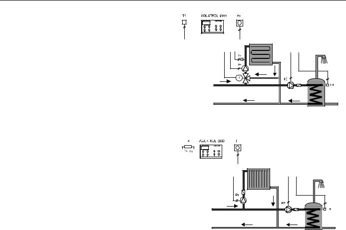
System 3
Mixed flow control for radiator or underfloor heating systems.
DHWS separate when DHWS sensor connected.
Optimisation and self-learning heating curve when optional space sensor or remote unit connected.
System 4
Optimiser control for systems with existing controls and requiring optimisation only.
DHWS separate when DHWS sensor connected.
Key
P1 = Heating pump |
T2 |
= Mixed flow water sensor |
P2 = DHWS pump |
T3 = Outside sensor |
|
B1 = Boiler 1 |
T4 = DHWS sensor |
|
B2 = Boiler 2 |
T5 |
= Boiler water sensor |
T1 = Space sensor/Remote Unit |
M = Motor/Actuator |
|
DHWS OPERATION
Separate DHWS
The DHWS operation is completely independent and has no effect on the demand for heat from the boiler(s). This is useful when DHWS is being supplied from a separate heat source. The DHWS output is active when the DHWS temperature falls 5 K below the DHWS setpoint.
Combined DHWS
There are three variants for combined DHWS; DHWS priority, shifting priority and parallel operation. In all three cases a demand for DHWS occurs when the DHWS temperature falls 5 K below the DHWS setpoint.
1. DHWS Priority
In heating circuits with no mixing valve (and no mixed flow temperature sensor), the DHWS has priority over the heating.
2. DHWS Shifting Priority
In heating circuits with a mixing valve where the boiler temperature is less than 10 K above the DHWS setpoint the mixing valve will be closed giving DHWS priority. If there is extra heat available and the boiler temperature is more than 20 K above the DHWS setpoint, the mixing valve will be controlled at the calculated setpoint. The mixed water temperature setpoint is reduced when the boiler temperature lies between these two values.
3. DHWS Parallel
In heating circuits with a mixing valve the heating circuit will operate normally during a demand for DHWS.
3 |
EN0R 8441 |
 Loading...