


 Loading...
Centrale
Controller
Manuel de l’utilisateur
301C
User Manual
M-510324 7/10

Controller Unit
301C
User Manual
M-510324 7/10

Notices and Trademarks
Copyright by Honeywell International Inc.
July 2010
While this information is presented in good faith and believed to be accurate, Honeywell disclaims the implied warranties of merchantability for a particular purpose and makes no express warranties except as may be stated in its written agreement with and for its customers.
In no event is Honeywell liable to anyone for any indirect, special or consequential damages. The information and specifications in this document are subject to change without notice.
This manual covers software version 3.086.
Honeywell Analytics
405 Barclay Boulevard
Lincolnshire, Illinois 60069
M-510324 |
301C User Manual |
iii |
7/10 |
Honeywell |
|
Symbol Definitions
The following table lists the symbols used in this document to denote certain conditions:
Symbol |
Definition |
ATTENTION: Identifies information that requires special consideration
TIP: Identifies advice or hints for the user, often in terms of performing a task
REFERENCE _ INTERNAL: Identifies an additional source of information within the bookset.
Indicates a situation which, if not avoided, may
CAUTION result in equipment or work (data) on the system being damaged or lost, or may result in the
inability to properly operate the process.
CAUTION: Indicates a potentially hazardous situation which, if not avoided, may result in minor or moderate injury. It may also be used to alert against unsafe practices.
CAUTION: Symbol on the equipment refers the user to the product manual for additional information. The symbol appears next to required information in the manual.
WARNING: Indicates a potentially hazardous situation which, if not avoided, could result in serious injury or death.
WARNING symbol on the equipment refers the user to the product manual for additional information. The symbol appears next to required information in the manual.
M-510324 |
301C User Manual |
v |
7/10 |
Honeywell |
|

INTRODUCTION ............................................................ |
11 |
Intended Use ......................................................................................... |
11 |
Receiving and Unpacking ...................................................................... |
11 |
Installation Instructions ...................................................................... |
12 |
Basic Guidelines .................................................................................... |
12 |
Surface Mount Installation..................................................................... |
13 |
Wiring Details .................................................................................... |
14 |
Power Connections ........................................................................... |
16 |
Communication Connections ............................................................ |
16 |
Settings for Specific Transmitters ...................................................... |
16 |
Relay Output ..................................................................................... |
17 |
Jumper Use Instructions ........................................................................ |
18 |
GETTING STARTED ...................................................... |
19 |
Initial Startup ......................................................................................... |
19 |
Datalogger (SDcard) ............................................................................. |
19 |
Programming Interface...................................................................... |
20 |
Keypad Functions .................................................................................. |
20 |
LED Definitions ...................................................................................... |
21 |
System Operation .................................................................................. |
21 |
SYSTEM PROGRAMMING ............................................ |
22 |
|
Tx Info Menu ..................................................................................... |
|
25 |
Ident Menu ............................................................................................ |
|
26 |
Product and Sensor Types ..................................................... |
27 |
|
COM Menu ............................................................................................ |
|
29 |
Scale Menus (1 and 2) .......................................................................... |
30 |
|
Detection Menu ..................................................................................... |
|
31 |
Display Menu ......................................................................................... |
|
32 |
Alarm A, B and C Menus ....................................................................... |
33 |
|
Servicing and Operating Menus ............................................................ |
34 |
|
Status Code ........................................................................................... |
|
35 |
Erase Current Tx ................................................................................... |
|
35 |
Change Tx Address ............................................................................... |
|
36 |
Groups Menu ..................................................................................... |
|
37 |
Creating Groups .................................................................................... |
|
38 |
Deleting Groups .................................................................................... |
|
39 |
|
|
|
M-510324 |
301C User Manual |
vii |
7/10 |
Honeywell |
|

Event Menu ....................................................................................... |
|
40 |
Action Menu ........................................................................................... |
|
42 |
Delays Menu .......................................................................................... |
|
43 |
Latch Mode............................................................................. |
|
44 |
Conditions .............................................................................................. |
|
45 |
Status ..................................................................................................... |
|
49 |
Database................................................................................................ |
|
49 |
Acquisition Menu ............................................................................... |
|
50 |
Starting and Stopping Tx Logging .......................................... |
51 |
|
Starting and Stopping Event Logging ..................................... |
52 |
|
Copy Menu ........................................................................................ |
|
53 |
Configuration ..................................................................................... |
|
53 |
Parameters ............................................................................................ |
|
54 |
System Log Menu .................................................................................. |
|
55 |
Config Menu ...................................................................................... |
|
56 |
Network Menu ................................................................................... |
|
61 |
Remote Calibration ................................................................................ |
|
63 |
Tests Menu ........................................................................................ |
|
65 |
Test Sequence ....................................................................................... |
|
67 |
Normal Mode ......................................................................................... |
|
69 |
Single Tx Mode ...................................................................................... |
|
69 |
Debug Mode .......................................................................................... |
|
69 |
Simulation Mode .................................................................................... |
|
70 |
Bacnet Menu .......................................................................................... |
|
72 |
Changing BACNet values ....................................................... |
75 |
|
Wireless Network Menu ..................................................................... |
|
77 |
Parameters Menu .................................................................................. |
|
78 |
Changing PAN ID or RF Channel ........................................... |
80 |
|
Diagnostics Menu .................................................................................. |
|
82 |
Nodes Menu ........................................................................................... |
|
83 |
New Node Menu .................................................................................... |
|
87 |
Hibernate Menu ..................................................................................... |
|
88 |
Reset Network Menu |
............................................................................. |
88 |
Status Log Menu .................................................................................... |
|
89 |
Consolidate Route Menu ....................................................................... |
89 |
|
BACnet/IP MODULE ......................................................................... |
|
91 |
Specifications ......................................................................................... |
|
91 |
BACnet Objects ..................................................................................... |
|
91 |
Analog Input ........................................................................... |
|
92 |
viii |
301C User Manual |
M-510324 |
|
Honeywell |
7/10 |
Analog Value .......................................................................... |
92 |
Binary Input ............................................................................ |
92 |
Binary Output ......................................................................... |
93 |
Binary Value ........................................................................... |
93 |
Device .................................................................................... |
93 |
Object Names ......................................................................... |
94 |
Protocol Implementation Conformance Statement ............................ |
99 |
BACnet Protocol Implementation Conformance Statement .................. |
99 |
Specifications .................................................................................. |
105 |
LIMITED WARRANTY ................................................. |
107 |
Limited Warranty ................................................................................. |
107 |
Re-Stocking Policy .............................................................................. |
107 |
Exclusions ........................................................................................... |
108 |
Warranty Limitation and Exclusion ..................................................... |
108 |
Disclaimer of Unstated Warranties ...................................................... |
109 |
Limitation of Liability ............................................................................ |
109 |
M-510324 |
301C User Manual |
ix |
7/10 |
Honeywell |
|

Introduction
Introduction
The 301C controllers act as nerve centers for gas detection networks, providing continuous monitoring for up to 96 connected units (plus 1 301ADI). Since the controllers are factory programmed to the owner’s specifications, installation is limited simply to mounting and connecting them. Once installed and connected, the controllers allow the user to monitor, adjust, or reconfigure an entire network of units.
The 301C has a supplementary option of the wireless coordinator that enables this controller to communicate with and manage up to 25 wireless gas detection devices in addition to its regular capabilities.
Intended Use
The controller is intended to monitor an entire gas detection network around the clock. The unit offers logging capabilities, creating log files of all transmitter concentrations and alarms for analysis. The unit is also equipped with grouping or zoning capabilities that allow users to query and monitor specific groups of transmitters or specific transmitter zones.
Receiving and Unpacking
Upon receiving the controller unit:
•Check that the package is undamaged
•Carefully open the package.
•Locate the packing slip or purchase order and verify that all items on the order are present and undamaged
Note: If the package or any of its contents are damaged, please refer to the Warranty section at the back of the manual for instructions.
M-510324 |
301C User Manual |
11 |
7/10 |
Honeywell |
|

Introduction
Installation Instructions
Installation Instructions
Basic Guidelines
Follow these instructions to the letter to ensure that the equipment will function properly. Failure to respect these guidelines will release Honeywell Analytics from any responsibility in the event of improper functioning:
•Locate all units in areas easily accessible for service.
•Avoid locations where instruments are subject to vibrations
•Avoid locating units near sources of electromagnetic interference
•Avoid locating units in areas subject to significant temperature swings
•Verify local requirements and existing codes that may impact choice of location.
12 |
301C User Manual |
M-510324 |
|
Honeywell |
7/10 |
Introduction
Installation Instructions
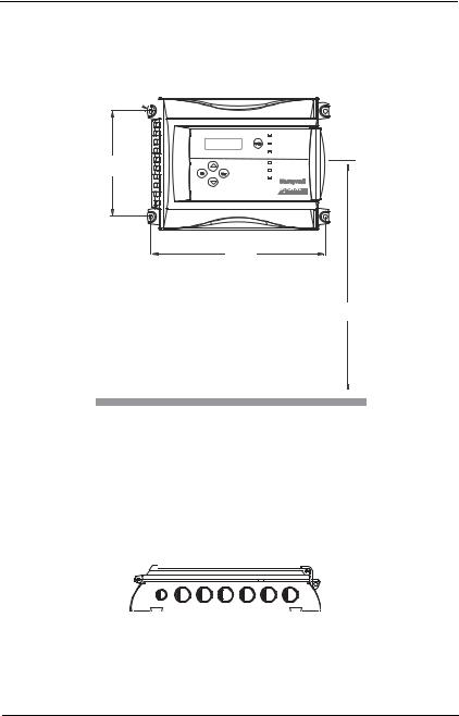
Surface Mount Installation
It is recommended that controllers be installed 5 feet (1.5 m) above the floor, at approximate eye level.
Ø .5cm ¼”


17.4 cm
6 13/32”
26.8 cm
10 9/16”
1.5m
5’
Mark the holes as shown:
•Height markers 6 13/32” apart
•Width markers 10 9/16” apart
•Pre-drill 1/4” mounting holes as needed
•Securely mount the 301C using the appropriate screws
Wiring for the unit must be passed through the knock-outs provided at the bottom of the unit.
M-510324 |
301C User Manual |
13 |
7/10 |
Honeywell |
|

Introduction
Wiring Details
Wiring Details
The diagram below provides the details required to connect the 301C with the wireless communication module (coordinator). This module allows the controller to communicate with and manage the 301W wireless gas detectors.
Details concerning power supply, cables, capacities, etc., are provided in the Specifications section at the back of this manual.
|
9XOFDLQ ,QF |
|
|
|
|
|
|
|
9$ &:35% |
|
|
. |
|
- |
|
|
0DGH LQ &DQDGD |
|
|
|
|
|
|
|
|
|
/ |
|
|
|
|
|
|
|
|
- |
|
|
|
|
Wireless |
|
|
|
|
|
21 |
|
communication module |
|
|
|
|
||
SD Card |
- |
|
3 |
/(' |
|
|
|
|
|
5(6(7- |
|
|
|
||
|
|
|
|
|
5(/$< |
|
|
|
|
|
|
|
|
- |
&1 |
|
' |
' |
|
|
5(/$< |
|
|
|
- |
. |
|
|
|||
|
|
|
|
- |
|
|
|
|
|
|
|
|
|
|
21 |
|
|
|
|
/(' |
|
|
|
|
|
|
|
|
$/$50B$ |
|
|
|
|
|
|
|
/(' |
|
%= |
|
|
|
|
6,/(1&( |
|
|
|
|
|
|
|
|
/ |
|
|
|
|
|
|
6: |
|
|
|
|
|
|
|
$/$50B% |
|
|
|
|
|
|
|
/(' |
- |
|
|
|
|
|
LCD screen |
|
5 |
|
|
|
|
|
|
/(' |
|
|
|
|
|
|
|
|
5 |
|
|
5 |
5& |
- |
/(' |
|
|
|
$/$50B& |
End-of-line jumper |
|
|
|
position |
|
|
|
/(' |
/(' |
End-of-line specification: |
83 |
(17(5 |
6: |
6: |
|
- |
|
|
The E.O.L. jumper for |
|
5(6(7 |
channels 1-2-3-4 must |
|
|
always be in E.O.L. |
|
3&% &:5$ |
|
|
|
position. |
/()7 |
5,*+7 0$'( ,1 &$1$'$ |
6: |
6: |
6+'1
-
9LQ
9 9
V+ 
PREVIOUS
V- 
|
(2/ |
- |
(2/ |
|
(2/ |
|
& |
|
|
02'8/((7+(51(7 |
|
|
|
|
|
|
|
(2/ |
5& |
|
|
|
|
|
|
|
'2:1 |
|
|
|
(6& |
|
|
|
|
|
|
6: |
|
|
|
6: |
|
|
5& |
|
5& |
|
|
|
|
|
|
|
|
|
|
|
|
|
5& |
|
|
|
|
|
|
|
5 |
|
|
|
|
|
|
|
9RXW |
5 |
|
|
|
|
|
|
|
|
|
|
|
|
|
|
|
5 - |
|
|
|
|
|
- |
|
|
|
|
|
|
|
|
|
|
|
|
|
|
- |
|
|
|
|
|
|
- |
|
|
|
|
|
|
|
|
|
9 9 |
|
$ % $ |
% 6+,(/' |
|
6+,(/' |
$ % $ % |
|
|
||
|
|
|
|
B 2 |
|
|
|
|
B 4 |
|
|
|
|
|
A 2 Channel 2 |
|
|
|
A 4Channel 4 (not used) |
||
|
|
|
|
B 1 |
|
|
|
B 3 |
|
|
|
|
|
|
A 1Channel 1 |
|
|
|
A 3 Channel 3 |
|
|
|
|
V- |
|
|
|
|
|
|
|
|
|
|
NEXT |
|
|
Grounding screw |
|
|
|
||
|
|
V+ |
|
|
|
|
|
|||
|
|
|
|
|
|
|
|
|
|
|
|
- |
- |
32:(5 |
|
|
|
. |
. |
/(' |
|
|
)$8/7 |
|
5(/$< |
5(/$< |
|
/(' |
|
|
|
|
7; |
|
|
|
|
/(' |
|
|
|
|
5; |
|
|
|
|
/(' |
|
|
|
|
|
|
|
- |
- |
1 2 1 & 1 2 1 & |
||||
RELAY OUTPUTS |
|
|||
6 |
4 |
2 |
Normally |
3+5 |
|
|
|
||
|
|
|
open |
4+6 |
|
|
|
Normally |
1+3 |
5 |
3 |
1 |
closed |
2+4 |
Always respect minimum voltage requirements at device
RISK OF ELECTRIC SHOCK
COMMUNICATION
Communication Wire Gauge: 2-24 AWG (Belden 9841) Twisted and shielded cable 2000 feet (600 m) per channel T-tap: 65 feet (20 m) / T-tap 130 feet (40 m) total
Channel Specifications:
Channel 1-2: Modbus,Vulbus protocol Channel 3: Modbus protocol only Communicates only with Vulcain transmitters
Channel 4: Modbus output Communicates only with VA301BDCM
 RISK OF ELECTRIC SHOCK
BacNet/IP MODULE (-BIP option)
Wireless Communication: Ethernet: 10/100-compatible with 10Base-T
ISM worldwide interface, RJ-45
Indoor range 30m
Visual Indicators:
Green LED LINK
Yellow LED ACT
14 |
301C User Manual |
M-510324 |
|
Honeywell |
7/10 |

Introduction
Wiring Details
The connectors, or ports, on the PCB allow various wiring to be connected to the controller. The wiring includes power, communication, BACNet and relays, each with an assigned position (and number) on the board:
J22 Power Input: Connect the power supply to the controller (see Wiring Details for cabling diagrams)
J23, J24 Communication inputs:
Relay Outputs 1-4:
SHDN jumper
EOL Resistors 1-4:
M-510324 |
301C User Manual |
15 |
7/10 |
Honeywell |
|

Introduction
Power Connections
Power Connections
The 301C requires a power range of 17-27 Vac, 50/60 Hz (8.64 VA), 18-36 Vdc, 350 mA @24 Vdc (8.4 VA). Polarization is not important in either AC or DC mode. The system must be grounded on the transformer and a dedicated circuit breaker must be used.
Communication Connections
Communication cables must be grounded using the shield terminal, using twisted and shielded pair Belden 2-24 AWG #9841 cable (or equivalent).
The network cabling can extend up to a limit of 2000 feet (609 m) per channel.
The length of a T-tap can reach 65 feet (20 m), up to a maximum of 130 feet (40 m) for all T-taps.
All wireless devices associated to the controller will automatically be detected and communicate with the controller using wireless communication protocols.
Settings for Specific Transmitters
Honeywell Sensepoint XCD Transmitters must be configured for 9600 baud, no parity, and a unique address. Honeywell XNX Universal Transmitters must be configured for 9600 baud and a unique address. Information on configuring each transmitter is in the associated technical manual.
16 |
301C User Manual |
M-510324 |
|
Honeywell |
7/10 |

Introduction
Relay Output
Relay Output
The relay output can withstand up to 5A at 30Vdc or 250Vac (resistive load only). Relays can be used to activate horns and strobes. Although each relay is programmed with a default setting (below), they can be configured using the controller programming menu.
RELAY OUTPUTS
|
|
|
|
|
|
|
|
|
|
|
|
|
|
N.O. |
|
COMM |
|
N.C. |
||
Normally open |
|
|
|
|
|
|
|
|
Normally closed |
||||
If relays are set to Normally closed, the relay is powered up with the controller and the device linked to the relay is functioning. The relay will shut down when the specified alarm condition is reached.
If the relay is set to normally open, the relay will remain off when the controller is powered up and the device connected to the relay will only be activated when the specified alarm condition is reached.
Note: These functions are reversed if the controller Failsafe mode has been activated.
M-510324 |
301C User Manual |
17 |
7/10 |
Honeywell |
|

Relay Output
Jumper Use Instructions
The jumpers on the controller PCB allow a variety of operations to be performed manually:
EOL 1-4: Enables the user to add End-Of-Line jumpers that improve communication signals. Put the jumper in R position (as shown on wiring diagram) to activate the End-of-Line termination. (R provides a resistance termination and RC provides resistance and condensator termination.)
SHDN: Enables the microcontroller to be reset or temporarily shut down. This function is used mainly when system wiring adjustments are needed (power off for safety).
Relays These jumpers allow the relay to be tested by activating it J29-J32 without having any effect on Events.
18 |
301C User Manual |
M-510324 |
|
Honeywell |
7/10 |
Getting Started
Relay Output
Getting Started
The controller units are customized to the purchaser’s specifications but they can be further programmed using the following menu options.
Initial Startup
Make sure that all wiring has been completed according to specifications in the wiring details before powering up the unit. When all is secure, remove the SHDN jumper to power-up the unit. It should only take a few seconds until the unit is fully operative.
Datalogger (SDcard)
The DLC (Data Logger Card) option for the controller collects data and stores it on a digital Flash memory card (SDCard). In the event that the card memory becomes full:
•Information logging is stopped
•No SDcard flag is displayed on-screen
•The SDcard LED blinks
See the Acquisition section for more details on starting and stopping the datalogging function.
CAUTION
Always deactivate datalogging function before removing the SDcard. Never remove the card when its LED is on.
M-510324 |
301C User Manual |
19 |
7/10 |
Honeywell |
|
Getting Started
Programming Interface
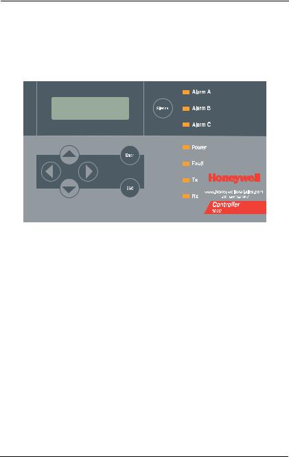
Programming Interface
The front panel of the 301C provides a programming keypad (buttons) and LEDs.
301C front panel Keypad
Keypad Functions
Each unit has 7 keypad keys, or buttons:
Arrows: |
Used to move the cursor through the various programming |
|
fields (Up, Down, Left and Right), or to adjust the display |
|
contrast (press and hold the up or down arrow until desired |
|
contrast is reached and release). |
ESC: |
Used to exit the programming menu or to cancel a change or |
|
input. |
Enter: |
Used to access the programming menu and to modify |
|
programming fields. |
Silence: |
Turns off the controller’s buzzer. |
20 |
301C User Manual |
M-510324 |
|
Honeywell |
7/10 |

Getting Started
Programming Interface
LED Definitions
The controller is equipped with 7 LEDs that provide a status for each function related to that indicator:
Alarm A: A blinking red light indicates that an event has been activated. A constant red light indicates that one or more transmitters has reached Alarm A or Alarm 1.
Alarm B When the red indicator is on, one or more transmitters has
|
reached Alarm B or Alarm 2. |
Alarm C |
When the red indicator is on, one or more transmitters has |
|
reached Alarm C. |
Power: |
Green indicates that the unit is powered up and functional |
Fault: |
When the amber LED is on, it indicates a fault (i.e. a |
|
communication, maintenance or device problem) |
Tx: |
When the amber LED is blinking, it indicates that the |
|
controller is sending information or requests on the |
|
communication channel. |
Rx: |
When the green LED is blinking, it indicates that the |
|
controller is receiving information. |
Each of these functions is linked to parameters programmed in the control unit, which we will discuss in the following section.
System Operation
The system operates in four different modes that allow it to use, analyze, debug, and simulate the actions that the system can perform. These modes are: Normal, Single Tx, Debug and Simulate. The default system operation mode is Normal. The other modes are available through the Tests menu (option 8 from the Main Menu).
Note: Systems services may be disrupted by some menu operations.
M-510324 |
301C User Manual |
21 |
7/10 |
Honeywell |
|

System Programming
Programming Interface
System Programming
The system’s Normal programming mode offers several menu options that are accessible from the main menu screen:
Tx Info: |
Allows transmitter parameters to be programmed |
Groups: |
Allows groups of transmitters to be set up |
Events: |
Allows events and event behavior to be programmed |
Acqui: |
Allows the datalogging feature to be activated or deactivated |
Copy: |
Allows data or parameters to be copied from the (controller) |
|
configuration to parameters |
Config: |
Allows system parameters and password to be set |
Network: Allows actions on the network to be performed, |
|
|
communication statistics to be consulted, and remote |
|
calibrations to be performed |
Tests: |
Allows each device to be tested sequentially (inputs, outputs, |
|
communications, events, etc.) and operation of various |
|
parameters to be validated |
BACNet: |
Allows a device’s BACNet parameters to be set |
Wireless: Allows a network of wireless gas detection devices to be configured, monitored, and modified.
Note: Access to the programming functions is password protected. The default password is 2967.
The screen display shown below appears initially. This display can be configured to scroll among the information screens for each device connected to the controller.
VA301C |
|
Ver. 3.00 |
||||
|
|
|
Ad: 1 |
Gr:0 |
Ev:0 |
|
|
|
|
|
|
|
13:18:18 |
|
|
|
|
|
|
|
|
|
|
|
|
|
|
2007-01-17 |
|
|||||
If one or more of the connected devices is in an alarm mode, the controller will only scroll between the main information screen and the screens for device(s) in alarm mode. In this case, you must scroll manually to view screens for other devices.
22 |
301C User Manual |
M-510324 |
|
Honeywell |
7/10 |

System Programming
Programming Interface
The information screen also displays icons representing certain system functions. Here is a list of possible icons and their meaning:
Icon |
Description |
BACNet: Indicates that there is a BACNet module present and that it is communicating with the controller.
BACNet error: Indicates that a BACNet module is present but communication with the controller has failed (error)
Debug: Indicates whether the controller is in debug mode (Single TX, Debug or Simulation modes). When in simulation mode, SIM appears next to this icon.
Log: Indicates that either “Tx Logging” or “Event logging” is enabled.
Log error: Indicates that an error occured during TX or
Event logging. All logging functions are stopped.
SDC: Indicates that an SDcard is present and functionning. The icon “fills” (from white to black) progressively as memory is used. A white icon indicates empty memory and black indicates full memory.
SDC error: If this symbol persists for more than 5 seconds, an SD card card is present but not functioning properly.
Wireless network: Indicates that the wireless network coordinator (wireless communication module) is present and communicating with the controller.
Wireless network error: Indicates that the wireless network coordinator (wireless communication module) is present but is not communicating with the controller.
M-510324 |
301C User Manual |
23 |
7/10 |
Honeywell |
|
System Programming
Programming Interface
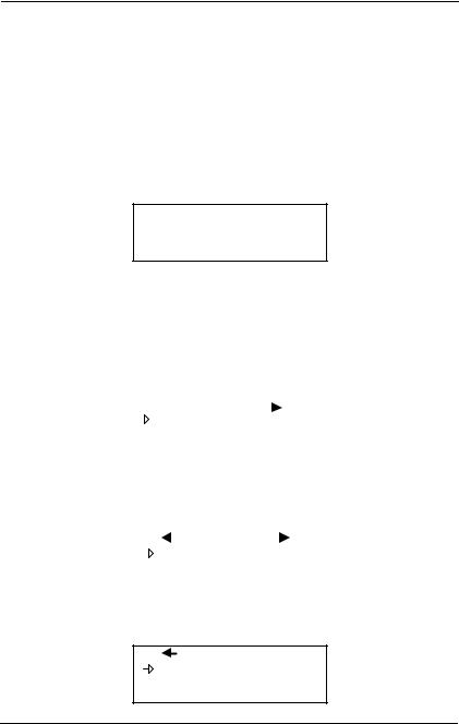
Since the controller’s programming functions are password protected, it is necessary to access the login screen:
•Press Enter to access the programming options. The password screen appears:
•Use the keypad Up or Down arrows to increase or decrease the value, one digit at a time, starting with the first digit
•When all the digits of the password are correct, press Enter to access the programming functions.
PASSWORD
_ _ _ _
The first MENU options screen appears. Use the keypad arrows to navigate through multiple screens to the desired function and press Enter to access it.
|
|
|
MENU |
|
|
|
|
|
|
|
|
|
|
|
|
1. |
Tx Info |
3. |
Events |
|
|
||||||
2. |
Groups |
4. |
Aqui |
|||
|
|
|
|
|
|
|
|
|
|
|
|
MENU |
|
|
|
|
|
|
|
|
|
|
|
|
|
|
5. |
Copy |
7. |
Network |
|||
|
||||||||
6. |
Config |
8. |
Tests |
|||||
|
|
|
|
|
|
|
|
|
MENU
9.BACNet
10.Wireless
24 |
301C User Manual |
M-510324 |
|
Honeywell |
7/10 |

System Programming
Tx Info Menu
Tx Info Menu
Tx Info is the menu option that is dedicated to transmitter information and contains several sub-menu options. The exact list of screens will vary depending on the transmitter type. A summary is presented below with details on the following pages
Ident: |
Allows the network component’s |
|
identification information to be |
|
viewed. |
COM: |
Allows the communication |
|
protocol to be viewed or changed |
Detection |
Allows the detection range and |
or Scale(1) |
the unit of measurement |
and |
parameters to be viewed and |
Scale(2): |
changed |
Display: |
Allows the label (or name) of a |
|
|
specific component to be |
|
|
changed |
|
Alarms: |
Allow alarm thresholds to be |
|
|
viewed and sometimes changed. |
|
|
There can be significant |
|
|
variations in this screen |
|
|
depending on transmitter type. |
|
Status |
Transmitter and node status |
|
Displays: |
(in hexadecimal values) |
|
Erase or |
Erases or changes the |
|
Current Tx: Tx address |
|
|
|
|
|
M-510324 |
301C User Manual |
25 |
7/10 |
Honeywell |
|

System Programming
Tx Info Menu
Ident Menu
The Ident, or identification menu allows a component’s network ID to be consulted:
1. Tx Info |
001 |
|
|
|
|
||
-Ident- |
|
|
|
 NotVul
CO2 (IR)
The upper right corner of the screen shows the component’s address. If the address of the device whose information must be viewed is known:
•Use the arrows to move the cursor arrow to the on-screen address
•Press Enter (the value can be edited while the number is flashing)
•Use the up or down arrows to increase or decrease the value
•Press Enter again to validate the entry and display the information for the desired device.
The bottom left corner of the display shows the transmitter name (ex.: 301D2 - product name) and the sensor type (ex.: CH4 - methane sensor). These values can also be changed for Group or Vulbus product types. The procedure is identical for both fields:
Programming or changing a product or sensor type
•Use the arrows to move the cursor to the product type field.
•Press Enter to select the field (the value can be modified when flashing)
•Use the arrows to scroll through the list of product types and press Enter when the desired product or sensor appears
26 |
301C User Manual |
M-510324 |
|
Honeywell |
7/10 |

System Programming
Tx Info Menu
Product and Sensor Types
This is a list of all the (preprogrammed) product types available from the Identification option in the Tx Info menu.
1. Tx Info |
121 |
|
|
|
|
||
-Ident- |
|
|
|
 301W
301W
CO2 (IR)
The order of the products below is not necessarily the order in which they will appear in the controller
|
|
Product Types |
||||
|
|
Addresses 1-96 |
||||
VA301D2 |
|
VA301AP |
|
XNX |
||
90DM3R |
|
VASQN8X |
|
XCD |
||
VA301IRF |
|
VA301EM |
|
VA201R |
||
IRT100 |
|
VA301EMRP |
|
VA201T |
||
EC-F9 |
|
GsPnt2 |
|
90DM2 |
||
VA201T2 |
|
S301RLC |
|
VA201D |
||
VA301T |
|
(Std.Device)* |
|
VA301D |
||
GsPnt |
|
VA901T |
|
NotVul |
||
RgRt3 |
|
|
|
|
|
|
|
|
|
|
|
|
|
|
|
Product Types |
||||
|
|
|
|
|
||
|
Addresses 97-120 |
|
Addresses 121-170 |
|||
|
301ADI |
|
(?) |
|
|
|
|
(?) |
|
|
301W |
||
|
|
|
|
301RW |
||
|
|
|
|
301RPT |
||
|
|
|
|
|
|
|
* E3Point and 420MDBS are examples of standard devices.
Note: When Group is selected as a product type, the remaining Tx INFO screens are not accessible (because each product in the group has already been individually programmed). Only the Ident and Erase current Tx screens will be available.
M-510324 |
301C User Manual |
27 |
7/10 |
Honeywell |
|

System Programming
Tx Info Menu
The sensor type list applies to address ranges 1-96 and is not dependent on the type of product selected. Devices in the address range from 97-170 will display a BACNet object identifier, rather than a sensor type.
*An additional Product Type, simply called “Group”, represents a group created in the Groups Menu in the controller. When scrolling through the available product type list, this name will appear as many times as there are groups created in the controller (example: Group 1, Group 2, Group 3, etc.). If a group is selected as the product type, then the sensor type options are limited to MIN, MAX and MEAN.
28 |
301C User Manual |
M-510324 |
|
Honeywell |
7/10 |
Loading...