


BC7000L1000

CONVERSION WIRING DIAGRAMS
FOR BC7000L1000
The diagrams and instructions contained in this booklet are for converting the following model
programmers to BC7000 Microcomputer Based Burner Control System.
TABLE OF CONTENTS
Page
Section l . . . . . . . . . . . . . . . . . . . . . . . . . . . . . . . . . . . . . . . . . . . . . . . . . . . . . . . . . . . . . . . . . . . . . . . . . . . . . . . . . . . . . . . . . . . . . . . . . . . . . . . . ...2
Fireye C, D, and E-Series
Section II . . . . . . . . . . . . . . . . . . . . . . . . . . . . . . . . . . . . . . . . . . . . . . . . . . . . . . . . . . . . . . . . . . . . . . . . . . . . . . . . . . . . . . . . . . . . . . . . . . . . . . . . ...6
Fireye P-Series
Section III . . . . . . . . . . . . . . . . . . . . . . . . . . . . . . . . . . . . . . . . . . . . . . . . . . . . . . . . . . . . . . . . . . . . . . . . . . . . . . . . . . . . . . . . . . . . . . . . . . . . . . . . 13
Honeywell R4126, R4127, R4181
Section lV . . . . . . . . . . . . . . . . . . . . . . . . . . . . . . . . . . . . . . . . . . . . . . . . . . . . . . . . . . . . . . . . . . . . . . . . . . . . . . . . . . . . . . . . . . . . . . . . . . . . . . . . 23
Honeywell R4140, R4150 with 20 Terminal Subbase (120 V only)
Section V . . . . . . . . . . . . . . . . . . . . . . . . . . . . . . . . . . . . . . . . . . . . . . . . . . . . . . . . . . . . . . . . . . . . . . . . . . . . . . . . . . . . . . . . . . . . . . . . . . . . . ...29
Honeywell R4150 with 13 or 15 Terminal Subbase
1. Installer must be a trained, experienced, flame safeguard control service technician.
2. Disconnect power supply before beginning installation to prevent electrical shock and
equipment damage.
3. All wiring must comply with applicable local electrical codes, ordinances, and regulations.
4. Voltage and frequency of the power supply and flame detector(s) connected to this control
must agree with those marked on the device.
5. Loads connected to the control terminals must not exceed those listed in the SPECIFI-
CATIONS section.
6. All external timers must be listed or component recognized by authorities having
jurisdiction, for the specific purpose for which they are used.
7. Perform all required checkout tests after installation is complete.
IMPORTANT
For on-off, gas-fired systems, some authorities having jurisdiction prohibit the wiring of any
limit or operating contacts in series with the main fuel valve(s).
P.G.
Rev. 6/89
Form Number 66-6002—4
©Honeywell Inc. 1989

SECTION I
FIREYE C, D, E-SERIES CONTROL
120 V ONLY
DIRECTIONS:
1. Disconnect all power to programmer.
2. Remove old programmer from subbase (trade-in to Honeywell Authorized Flame Safeguard
Distributor).
3. Mark all wires on subbase; i.e., wires connected to terminal “D” should be marked “D.”
Disconnect wires as they are marked.
4. Remove old subbase.
5. Mount Q520A subbase.
6. Connect wires to subbase per attached cross reference. Pay close attention to footnotes. For
example: To convert a Fireye 70D10 to a BC7000, the wire marked “P” would connect to
terminal #3 on the Q520. The wire marked “8” would connect to Q520 terminal #15.
7. The symbol “
“ designates a footnote. Study these footnotes carefully.
8. Plug in the BC7000. Make sure you select the proper amplifier, detector and program module
for the application.
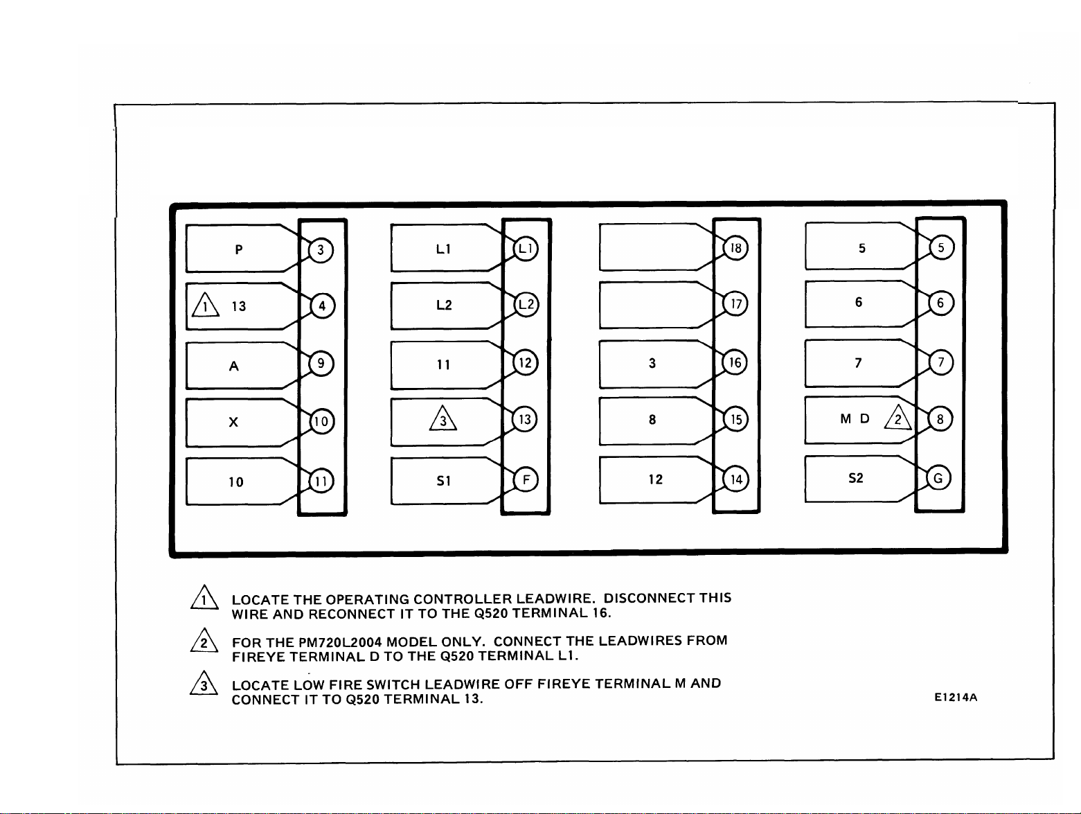
E1214A
FIREYE 70D10/26CF6-5022/26 CU6-5065
EP160/EP161/EP170
TO
BC7000L/PM720L2004 or 1030

E1215B
FIREYE 24CJ5 - 5010/5011/3010/3011
25CU6 5062/5063/RS-2E
70D30/26CF6 5020/5021/1010/1011
EP380/EP381/EP390
TO
BC7000L/PM720M2002
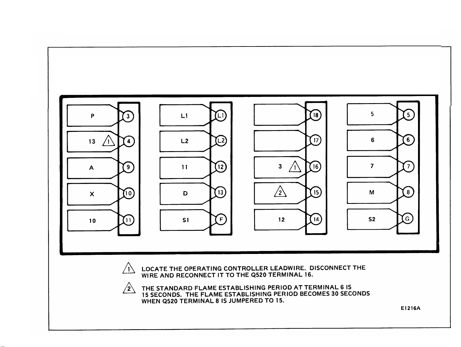
E1216E
FIREYE 24CJ5 5015
70D20/26CF6 5023/25 CU65055
EP260/EP261/EP270
TO
BC7000L/PM720G2005
SECTION II
FIREYE P-SERIES CONTROLS
120 V ONLY
DIRECTIONS:
1.
2.
3.
4.
5.
6.
7.
8.
Disconnect all power to programmer.
Remove old programmer from subbase (trade-in to Honeywell Authorized Flame Safeguard
Distributor).
Mark all wires on subbase; i.e., wires connected to terminal “D” should be marked “D.”
Disconnect wires as they are marked.
Remove old subbase.
Mount Q520A subbase.
Connect wires to subbase per attached cross reference. Pay close attention to footnotes. For
example: To convert a Fireye 26RJ81016 to a BC7000, the wire marked “B” would connect to
terminal #10 on the Q520. The wire marked “W” would connect to Q520 terminal #14.
The symbol “ “ designates a footnote. Study these footnotes carefully.
Plug in the BC7000. Make sure you select the proper amplifier, detector and program module
for the application.
6

E1221A
FIREYE 26RJ8 1016, 1016T
26RJ8 1012, 1012T, 6012, 6012T
TO
BC7000L + PM720G2005
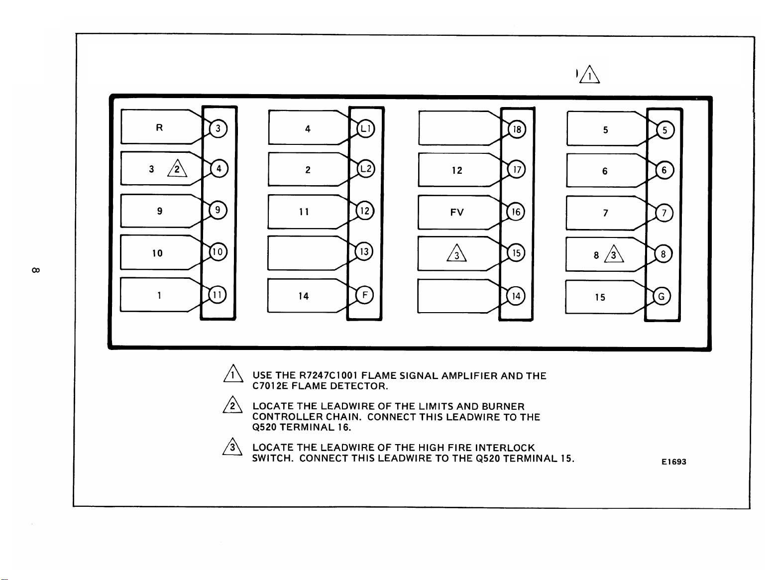
E1693
FIREYE 25RLJ84580
TO
BC700L + PM720L1030
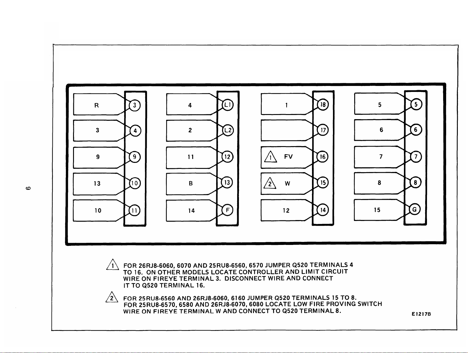
E1217B
FIREYE 25RU8 6560, 6570,6580
26RJ8 6060, 6070,6080, 6160 TO
BC7000L + PM720L1030
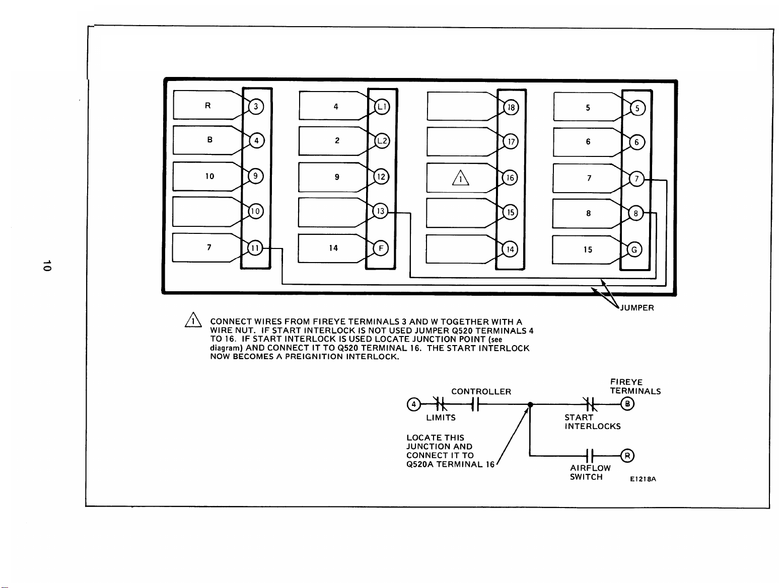
E1218A
FIREYE 29RF5 1001, 1009, 6009 TO
BC7000L + PM720G2013
 Loading...