


FBII Security System
OMNI®400/OMNI®600
OMNI®624/OMNI®848
User Guide
N9939V5 4/04 Rev. A

Table Of Contents |
|
QUICK REFERENCE .................................................................................................................... |
3 |
INTRODUCTION ........................................................................................................................... |
6 |
SYSTEM REFERENCE ................................................................................................................ |
7 |
ARMING THE SYSTEM.............................................................................................................. |
10 |
DISARMING THE SYSTEM ....................................................................................................... |
14 |
USER CODES ............................................................................................................................. |
15 |
MISCELLANEOUS COMMANDS.............................................................................................. |
16 |
USING A PAGER........................................................................................................................ |
22 |
TESTING THE SYSTEM ............................................................................................................. |
24 |
RECOMMENDATIONS ON SMOKE DETECTORS.................................................................. |
25 |
EMERGENCY EVACUATION .................................................................................................... |
26 |
GLOSSARY ................................................................................................................................. |
27 |
RADIO FREQUENCY EMISSIONS STATEMENTS.................................................................. |
29 |
TELEPHONE/MODEM INTERFACE STATEMENTS ............................................................... |
29 |
TELEPHONE OPERATIONAL PROBLEMS ............................................................................. |
30 |
0560 DECLARATION OF CONFORMITY ............................................................................ |
30 |
LIMITATIONS OF THIS ALARM SYSTEM................................................................................ |
31 |
ONE YEAR LIMITED WARRANTY............................................................................................ |
32 |
- 2 -
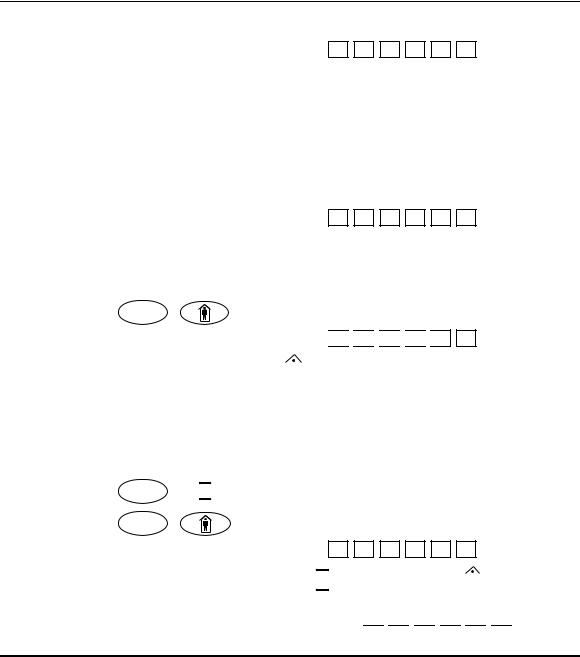
Quick Reference
TO ARM THE SYSTEM
1. Check to make sure the system is ready. (The Green READY light is lit.)
2. Enter your 4-digit (or 6-digit) user code. The ARMED/ light will light.
3. Exit through a door designated by your installer as an exit/entry door.
NOTE: If you DO NOT EXIT during the exit time and your system installer has programmed your system for Auto-Stay, the system will arm in the Auto-Stay mode.
TO DISARM THE SYSTEM
1. Enter through a door designated by your installer as an exit/entry door.
2. Enter your 4-digit (or 6-digit) user code. The ARMED/ light will go out.
TO ARM THE SYSTEM AND STAY INSIDE
1. Check to make sure the system is ready. (The Green READY light is lit.)
2. Press STAY / |
. |
3. Enter your 4-digit (or 6-digit) user code. 


 The ARMED/
 light and STAY/
 light will both light.
REMEMBER: Unless the Quick Exit feature is enabled, you must disarm the system if you want to open the door or leave the premises after the exit time has passed.
TO ARM THE SYSTEM IN INSTANT MODE, AND STAY INSIDE
1.Check to make sure the system is ready. (The Green READY light is lit.)
2.Press INSTANT /  .
.
3. Press STAY / |
. |
4. Enter your 4-digit (or 6-digit) user code.
The ARMED/ light, the INSTANT/
 light, and the STAY/
 light will all be lit.
TO RESET SMOKE DETECTOR
1. Enter your 4-digit (or 6-digit) user code twice. 


- 3 -

Quick Reference (cont)
The following table lists the “Quick Commands” available with this control.
Key |
Description |
Keypads |
Comments |
# 1 |
Quick Arm – if system is ready |
All keypads |
Allows you to arm the system without requiring your |
|
|
|
user code. User code is always needed to disarm |
|
|
|
the system. |
# 2 |
Force Arm – bypasses faulted |
All keypads |
Allows you to arm the system even if some zones |
|
zones |
|
are faulted. These zones will be automatically |
|
|
|
bypassed and will be unprotected. |
|
|
|
|
BYPASS |
Quick Bypass |
All keypads |
If not enabled, requires user code with authority 1, |
|
|
|
2, or 3. |
nn (zone no.) |
|
|
|
# 3 |
Set Time and Date |
All keypads |
May require user code. |
# 4 |
Zone Directory |
LCD* only |
Lists each zone with its descriptors. Mode |
|
|
|
terminates after last enabled zone. |
# 50 |
Quick Help (OMNI624/848 only) |
LCD* only |
Provides a listing of all quick commands available in |
|
|
|
the system. |
# 51 |
Show Time and Date |
LCD* only |
May also require code. |
# 52 |
Show Auto Arm Time |
LCD* only |
May also require code. |
# 53 |
User Event Log View |
LCD* only |
Also needs user code with authority level 1 or 2. |
# 54 |
Set Auto Arm Time of Current |
All keypads |
By partition (OMNI624/848) or system |
|
Partition (OMNI624/848) or |
|
(OMNI400/600), may also require code. |
|
System (OMNI400/600) |
|
|
# 55 |
Display Firmware Version |
LCD* only |
Displays panel’s revision. |
# 56 |
Display Key Fob Low Batteries |
All keypads |
Wireless Key Fob battery test. |
|
(OMNI624/848 only) |
|
|
# 57 |
Door Strike |
All keypads |
Activate doorstrike or trigger. May require certain |
|
|
|
user code. |
# 58 |
Change/View Pager Number |
All keypads |
For keypad partition (OMNI624/848) or system |
|
|
|
(OMNI400/600), only LCD* shows phone number. |
# 6 |
Display/Toggle Chime Mode |
All keypads |
LCD* displays current state first, then offers to |
|
|
|
toggle. All others just toggle the state. |
# 7 |
Assign User to Other Partition |
All keypads |
Need user auth. of 1 or 2. Digit 4 (P) enables user |
|
or to Activate Paging |
|
to page. |
|
(OMNI624/848 only) |
|
Paging must be enabled and turned on. |
|
|
|
|
# 8 |
User Page Toggle |
All keypads |
Toggles if users should send page for |
|
|
|
Open/Close by partition (OMNI624/848) or by |
|
|
|
system (OMNI400/600). |
|
|
|
|
# 9 |
User On-line |
All keypads |
Connects to downloader while on line, disconnects |
|
|
|
home phone. |
# 0 |
Multi-Partition (OMNI624/848 |
All keypads |
LCD* displays current enables, 1, 2, 3 – P = 4 |
|
only) |
|
NOTE: An entry of 3 is available for the OMNI848 |
|
|
|
only |
* 2-line alpha display
- 4 -

Quick Reference (Cont’d)
The following table provides a summary listing of LED indications when using a LED keypad.
INDICATOR |
ON |
SLOW PULSE |
FAST BLINK |
SLOW BLINK |
(approx. 600mS ON |
(approx. 150mS ON |
(approx. 100mS ON |
||
|
|
– 600mS OFF) |
– 150mS OFF) |
– 900mS OFF) |
ARM / |
Armed |
Comm. Fail |
Alarm |
– |
|
|
|
|
|
AC/LB / |
AC good |
Syst Batt Trbl |
– |
– |
READY / |
Ready |
Program Mode |
Alarm memory |
– |
1 |
Zone Fault |
Zone Trouble |
Zone Alarm |
Zone Bypass |
2 |
Zone Fault |
Zone Trouble |
Zone Alarm |
Zone Bypass |
3 |
Zone Fault |
Zone Trouble |
Zone Alarm |
Zone Bypass |
4 |
Zone Fault |
Zone Trouble |
Zone Alarm |
Zone Bypass |
5 |
Zone Fault |
Zone Trouble |
Zone Alarm |
Zone Bypass |
6 |
Zone Fault |
Zone Trouble |
Zone Alarm |
Zone Bypass |
7 |
Zone Fault |
Zone Trouble |
Zone Alarm |
Zone Bypass |
8 |
Zone Fault |
Zone Trouble |
Zone Alarm |
Zone Bypass |
STAY / |
Stay Armed |
– |
– |
– |
|
|
|
|
|
INST / |
Instant Armed |
Arm disabled |
– |
– |
|
|
|
|
|
TRBL / |
– |
– |
– |
Phone Fail |
|
|
|
|
|
SUPER / |
– |
Bell Supr |
Zone Tamper |
– |
|
|
|
|
Other LED display combinations:
•Slow Pulse of ARM/ , AC/LB/
 , and READY/ LEDs indicate the system is in Walk Test Mode.
•Fast Blink of Zone and SUPER / LEDs indicate a tamper condition for the blinking zone.
- 5 -
Introduction
Congratulations on your decision to protect your home or business with the OMNI® security system. You have chosen a reliable, state-of-the-art security system that is remarkably easy to operate. Your system has been professionally installed by your local Security Company whose representative can explain the specifics of your system.
The keypad is the input and display device for your security system. Your Security Company representative will suggest the model most appropriate for your premises and your needs. There are three types of keypads that can be used with this system: LCD keypad (alpha display), Fixed-Word keypad (2-digit display), or LED keypad.
Since your system may use any of these keypads, the displays of all keypads are described in this manual.
The OMNI400, OMNI600, OMNI624, and OMNI848 are listed by Underwriters Laboratories for Household Fire and Burglary applications.
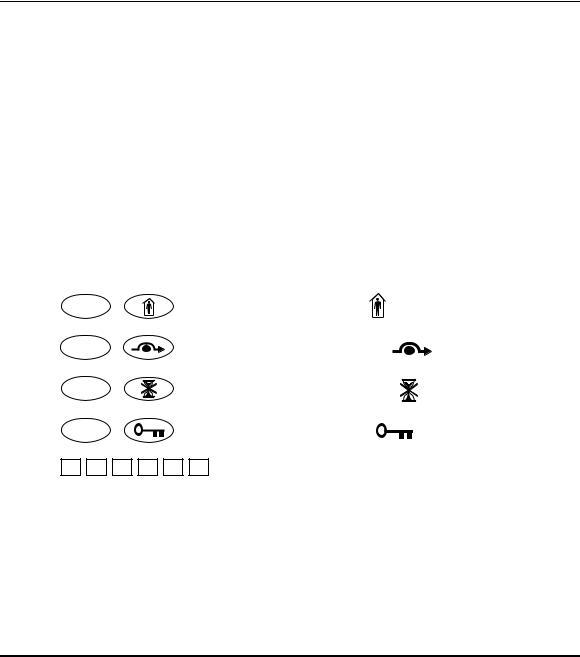
Throughout this manual, the following conventions are used to represent the keystrokes required to perform the following functions.
STAY |
/ |
Press Button labeled STAY or . |
|
BYPASS |
/ |
Press Button labeled BYPASS or |
. |
INSTANT |
/ |
Press Button labeled INSTANT or . |
|
CODE |
/ |
Press Button labeled CODE or |
. |
Enter 4-digit (or 6-digit) user code.
Please keep your manual in a convenient location so you can refer to it if needed.
- 6 -

System Reference
ZONE DESCRIPTIONS
In the following table, enter a description of the area of protection for each zone. Example: Zone 1 Windows on North side of building.
Zone 4 Main entrance to building.
Zone |
Description |
Zone |
Description |
1 |
|
25* |
|
2 |
|
26* |
|
3 |
|
27* |
|
4 |
|
28* |
|
5 |
|
29* |
|
6 |
|
30* |
|
7 |
|
31* |
|
8 |
|
32* |
|
9* |
|
33* |
|
10* |
|
34* |
|
11* |
|
35* |
|
12* |
|
36* |
|
13* |
|
37* |
|
14* |
|
38* |
|
15* |
|
39* |
|
16* |
|
40* |
|
17* |
|
41* |
|
18* |
|
42* |
|
19* |
|
43* |
|
20* |
|
44* |
|
21* |
|
45* |
|
22* |
|
46* |
|
23* |
|
47* |
|
24* |
|
48* |
|
*Zones 9 through 48 are not used with the OMNI400. Zones 13 through 48 are not used with the OMNI600. Zones 25 through 48 are not used with the OMNI624.
Entry time ________ Door __________ Exit time ________
Entry time ________ Door __________
Exit time is the same for all designated entry/exit doors.
- 7 -

System Reference (cont)
SEND-HELP ALERT
All keypads are equipped with emergency-pair keys. In order to activate the alert, both keys must be pressed at the same time. The type of keypad you have installed dictates which keys you press. Your installer will show you how to activate these emergency keys. The emergency keys used for all keypads are shown below.
The following SEND - HELP ALERT is programmed into my system:
KEYS |
|
DESCRIPTION |
# |
& |
T |
7 |
& |
9 |
1 |
& |
3 |
NOTE: These key combinations may also be programmed for other system functions.
PAGER ALERT
If programmed, a button on a designated keyfob may also be used to send an alert message to a pager. Ask your installer if this was done.
MONITORING STATION INFORMATION
Account #
Telephone #
- 8 -

System Reference (cont)
USER CODE ASSIGNMENTS
In the following table, enter the names of the individuals assigned to each user number.
User |
Assigned To… |
User |
Assigned To… |
1 |
|
33* |
|
2 |
|
34* |
|
3 |
|
35* |
|
4 |
|
36* |
|
5 |
|
37* |
|
6 |
|
38* |
|
7 |
|
39* |
|
8 |
|
40* |
|
9 |
|
41* |
|
10 |
|
42* |
|
11 |
|
43* |
|
12 |
|
44* |
|
13 |
|
45* |
|
14 |
|
46* |
|
15 |
|
47* |
|
16* |
|
48* |
|
17* |
|
49* |
|
18* |
|
50* |
|
19* |
|
51* |
|
20* |
|
52* |
|
21* |
|
53* |
|
22* |
|
54* |
|
23* |
|
55* |
|
24* |
|
56* |
|
25* |
|
57* |
|
26* |
|
58* |
|
27* |
|
59* |
|
28* |
|
60* |
|
29* |
|
61* |
|
30* |
|
62* |
|
31* |
|
63* |
|
32* |
|
64* |
|
*User Codes 16 through 64 are not used with the OMNI400 or OMNI600. User Codes 33 through 64 are not used with the OMNI624.
____ |
____ |
USER CODE NOTE: User codes can be either 4 digits or 6 digits, depending on installer |
4-digit |
6-digit |
programming. Ask your installer what type of user codes (4 or 6 digits) are being used in |
|
|
your system. When performing system functions, you must use the appropriate 4- or 6- |
|
|
digit user codes. |
|
|
|
|
|
- 9 - |
Arming the System
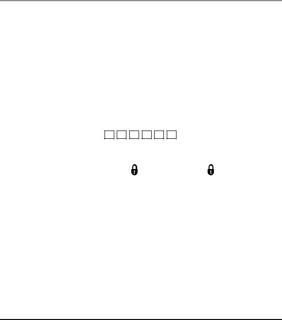
IS THE SYSTEM READY?
You can arm and disarm the burglar portion of your security system. Before you can arm the system, it must be “ready.” If you have a protected door open, or someone is moving in view of a motion detector, the system will not display the “READY” message.
The system is ready if the READY/ light is lit and the display shows:
|
LCD Keypad: |
|
Fixed-Word Keypad: |
LED Keypad: |
|
SYSTEM READY |
|
READY/ LED lit |
READY/ LED lit |
|
|
|
||
|
|
|
|
|
NOTE: If programmed by your installer, you may arm the system if a delay or interior zone is faulted. However, faulted zones must be restored before your exit time expires or an alarm or zone bypass will result. Ask your installer if your system has this feature and, if so, if it causes an alarm or zone bypass.
TO ARM THE SYSTEM AND LEAVE
Enter your user code.
The System ARMED/ light will go on and the display will show:
|
LCD Keypad: |
|
|
Fixed-Word Keypad: |
LED Keypad: |
|
ON: AWAY |
120s |
|
ARM/ LED lit |
ARM/ LED lit |
|
|
|
|
120 |
|
|
|
|
|
NOTE: The number 120 shown above for the LCD and Fixed-Word keypads indicates a counter that is updated every second and displays the amount of time remaining to exit without sounding an alarm.
Exit through a door designated by your installer as an exit/entry door. You must leave within the exit time programmed by your installer. Refer to the reference sheet for the time that has been set for your system.
This system can be programmed by the installer for the AUTOSTAY feature, which automatically bypasses interior zones programmed for AUTOSTAY if you arm the system and do not exit through a delay zone during exit time.
- 10 -
 Loading...