


50027910-001
Differential Pressure Switch
APPLICATION
The Honeywell differential pressure switch senses changes in duct air pressure to confirm air movement, providing a safeguard that airflow is present during the operation of installed IAQ equipment, including the TrueSTEAM Humidification System.
|
M27300 |
Fig. 1. Pressure switch. |
|
Table 1. Parts Included. |
|
Item |
Quantity |
Rubber Grommet |
2 |
|
|
M27302 |
|
Tubing Fitting Elbow |
2 |
|
|
M27323 |
|
Tubing, 1/4 in. ID |
10 ft |
Differential Pressure Switch (Fig. 1) |
1 |
Screws, #8 x 3/4 in. sheet metal |
2 |
Terminal Adaptor |
2 |
INSTALLATION INSTRUCTIONS
SPECIFICATIONS
SPST: normally open, snap-acting contacts
Pressure setpoint contacts: change at 0.04 in. W.C.
Electrical
5 amp resistive @ 24VAC
One common (C), One Normally Open (NO) quick-con- nect terminals
Operating Temperature: -40F to 190F (-40C to 88C)
Pressure Sample Taps
Black positive pressure tap. 1/4 in. outside diameter Grey negative pressure tap. 1/4 in. outside diameter Use with 1/4 in. inside diameter tubing (10 ft provided)
4-13/64 (107)
3-13/16 (97)

 5/64
5/64
(2)
FULL
R
3/16
(5)
Ø3-1/4 (83)
[2] 1/2 (13)
 [2] 1/4 (6)
|
C |
1 |
ASSEMBLED MEXICOIN |
|
1 |
|
|
|
2 |
|
3 |
2 |
3 |
|
|
 2-1/64 (51)
 1-19/32 (41)
Ø3/16
(5)
3-15/16
(100)
NEGATIVE |
|
PRESSURE |
27/32 |
PORT |
(21) |
POSITIVE
PRESSURE
PORT
COMMON (C) TERMINAL 1/4 (6) X 1/32 (1) THICK QUICK CONNECT
2 |
3 |
NO |
NC |
+ PI |
NORMALLY OPEN (NO) |
TERMINAL 1/4 (6) X 1/32 (1) |
|
|
THICK QUICK CONNECT |
M27301
Fig. 2. Pressure switch dimensions.
Mounting position: mount vertically (upright) with Honeywell logo right-side up.
Approvals
Underwriters Laboratories Inc. Approved: MP2168 Canadian Underwriter Laboratories Inc. Approved:
MP2168
69-2205-01
50027910-001 DIFFERENTIAL PRESSURE SWITCH
INSTALLATION
•Read these instructions carefully. Failure to follow them could damage the product or cause a hazardous condition. This control must be installed in accordance with the local code and regulations.
•Check ratings and descriptions given in the Specifications section to ensure the product is suitable for your application.
•Installer must be a trained, experienced service technician.
IMPORTANT
Do not install the switch in an area where temperature exceeds rating of -40F to 190F (-40C to 88C)
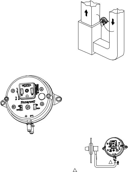
1.Disconnect power from the TrueSTEAM before installing.
2.Mount the switch vertically with pressure connectors facing down, using provided self-tapping screws to secure the switch to the duct.
IMPORTANT
Calibration accuracy requires that the switch be mounted vertically (as pictured in Fig. 3).
M27300
Fig. 3. Pressure switch—oriented vertically.
3.The return duct is recommended, however the switch can also be mounted to the supply duct.
A
B
SUPPLY DUCT INSTALL - AIR LINE ONLY TO TAP A,
CONNECTED TO THE + PORT ON THE AIR FLOW SWITCH
RETURN DUCT INSTALL - AIR LINE ONLY TO TAP B,
CONNECTED TO THE – PORT ON THE AIR FLOW SWITCH
SUPPLY/RETURN DUCT INSTALL - AIR LINE CONNECTED
TO BOTH THE + AND – PORTS ON THE AIR FLOW SWITCH
M27303
Fig. 4. Mounting the pressure switch.
4.Cut a 3/4-in. diameter hole in the duct within 10 feet of the switch to ensure the provided tubing reaches the pressure tap elbow.
5.Insert the grommet into the duct hole, then insert the tube elbow into the grommet.
6.Connect the tubing to the elbow fitting and the other end to the applicable pressure connection on the switch:
a.Black connection if installed on the supply
b.Grey connection if installed on the return
IMPORTANT
With low-speed airflow or variable speed systems it is recommended to run tubing to both the supply and return ducts.
INSIDE
OF DUCT
1
1CONNECT TUBING TO + CONNECTION IF PRESSURE TAP IS MOUNTED TO SUPPLY DUCT. CONNECT TO – IF PRESSURE
TAP IS MOUNTED TO RETURN DUCT. |
M27304 |
Fig. 5. Install tubing.
NOTE: You may cut the tubing to fit the connection length between the elbow fitting and switch. It is also recommended to secure the hose to existing structures to avoid accidental disconnection.
69-2205—01 |
2 |
 Loading...