


 Loading...
2020/4820/4820i
2D Cordless Imaging System
User’s Guide
™

Disclaimer
Honeywell International Inc. (“Honeywell”) reserves the right to make changes in specifications and other information contained in this document without prior notice, and the reader should in all cases consult Honeywell to determine whether any such changes have been made. The information in this publication does not represent a commitment on the part of Honeywell.
Honeywell shall not be liable for technical or editorial errors or omissions contained herein; nor for incidental or consequential damages resulting from the furnishing, performance, or use of this material.
This document contains proprietary information that is protected by copyright. All rights are reserved. No part of this document may be photocopied, reproduced, or translated into another language without the prior written consent of Honeywell.
© 2005-2008 Honeywell International Inc. All rights reserved.
Web Address: www.honeywell.com/aidc
Microsoft® Pocket PC 2002, Windows®, Windows NT®, Windows 2000, Windows ME, Windows XP, ActiveSync®, Outlook®, and the Windows logo are trademarks or registered trademarks of Microsoft Corporation.
The Bluetooth® word mark and logos are owned by Bluetooth SIG, Inc.
Other product names or marks mentioned in this document may be trademarks or registered trademarks of other companies and are the property of their respective owners.

Product Agency Compliance
USA
FCC Part 15 Subpart C
This device complies with part 15 of the FCC Rules. Operation is subject to the following two conditions:
1.This device may not cause harmful interference.
2.This device must accept any interference received, including interference that may cause undesired operation.
Caution: Any changes or modifications made to this equipment not expressly approved by Honeywell may void the FCC authorization to operate this equipment.
UL Statement
UL listed: UL60950-1 for I.T.E product safety.
Canada
Industry Canada
This device complies with Canadian RSS-210.
Operation is subject to the following conditions:
1.This device may not cause interference, and
2.This device must accept any interference, including interference that may cause undesired operation of this device.
Conformité à la règlementation canadienne
Cet appareil ISM est conforme à la norme CNR-210 du Canada.
Son fonctionnement est assujetti aux conditions suivantes :
1.Cet appareil ne doit pas causer de brouillage préjudiciable.
2.Cet appareil doit pouvoir accepter tout brouillage reçu, y compris le brouillage pouvant causer un fonctionnement indésirable.

cUL Statement
cUL listed: CSA C22.2 No.60950-1-03 for I.T.E product safety.
Europe
The CE mark on the product indicates that this device is in conformity with all essential requirements of the 1999/5/EC R&TTE Directive. In addition, complies to 2006/95/EC Low Voltage Directive, when shipped with recommended power supply. For further information please contact:
Honeywell Imaging & Mobility Europe BV
International Inc.
Nijverheidsweg 9-13
5627 BT Eindhoven
The Netherlands
Honeywell shall not be liable for use of our product with equipment (i.e., power supplies, personal computers, etc.) that is not CE marked and does not comply with the Low Voltage Directive. This equipment is intended for use throughout the European Community and has been assessed to the following standards:
EN 300 328
EN 301 489-1
EN 301 489-17
EN60950-1
EN60825-1
Waste Electrical and Electronic Equipment
Information
Honeywell complies with Directive 2002/96/EC OF THE EUROPEAN PARLIAMENT AND OF THE COUNCIL on waste electrical and electronic equipment (WEEE).
This product has required the extraction and use of natural resources for its production. It may contain hazardous substances that could impact health and the environment, if not properly disposed.
In order to avoid the dissemination of those substances in our environment and to diminish the pressure on the natural resources, we encourage you to use the appropriate take-back systems for product disposal. Those systems will reuse or recycle most of the materials of the product you are disposing in a sound way.
 The crossed out wheeled bin symbol informs you that the product should not be disposed of along with municipal waste and invites you to use the appropriate separate take-back systems for product disposal.

If you need more information on the collection, reuse, and recycling systems, please contact your local or regional waste administration.
You may also contact your supplier for more information on the environmental performances of this product.
Germany
If your product is marked with the GS symbol, then the product has been issued a GS certificate showing compliance to IEC 60950-1 and IEC 60825-1.
Australia/NZ
C-Tick Statement
 Conforms to AS/NZS 3548 EMC requirements.
Japan (4820i, 2020-5B)
Complies with Technical Regulations Conformity Certification of Specified Radio equipment.
Mexico
Safety approval conforms to NOM-019.
Comision Federal de Telecomunicaciones (radio aprobación)
International
!AN INCORRECT TYPE. The battery should be disposed of by a
qualified recycler or hazardous materials handler. Do not incinerate the battery or dispose of the battery with general waste materials.CAUTION: RISK OF EXPLOSION IF BATTERY IS REPLACED BY
Eye Safety Statement
LED
This device has been tested in accordance with IEC60825-1 LED safety, and has been certified to be a Class 1 LED device.
Laser Eye Safety Statement
If the following label is attached to your product, it indicates the product contains a laser engine or laser aimer:

LASER LIGHT. DO NOT STARE INTO BEAM CLASS 2 LASER PRODUCT
1.0 mW MAX OUTPUT: 650nM IEC60825-1: 1993+A1+A2
Complies with 21 CFR 1040.10 and 1040.11 except for deviations pursuant to Laser Notice No. 50, dated July 26, 2001.
This device has been tested in accordance with and complies with IEC60825-1: 1993+A1+A2 and 21 CFR 1040.10 and 1040.11, except for deviations pursuant to Laser Notice No. 50, dated July 26, 2001.
LASER LIGHT, DO NOT STARE INTO BEAM, CLASS 2 LASER PRODUCT, 1.0 mW MAX OUTPUT: 650nM.
Caution: Use of controls or adjustments or performance of procedures other than those specified herein may result in hazardous radiation exposure.
Radio Technology
Class II
CB Scheme
Certified to CB Scheme IEC 60950-1.
Solids and Water Protection
The 4820 has a rating of IP41, immunity of foreign particles and dripping water.
The 4820i has a rating of IP54, immunity of foreign particles and sprayed water.
Patents
Please refer to product packaging for patent information.

Required Safety Labels
Scanner
Compliance
Label locations
Item Number, Serial Number and Revision Information location

Base
Compliance
Label
locations
Item Number,  Serial Number and Revision Information location

Table of Contents
Chapter 1 - Getting Started
About This Manual ...................................................... |
1-1 |
Unpacking the System ................................................ |
1-1 |
Image Scanner Models ............................................... |
1-1 |
Cordless System: Main Components.......................... |
1-2 |
About the Battery ........................................................ |
1-2 |
Proper Disposal of the Battery .................................... |
1-3 |
Connecting the Base................................................... |
1-3 |
Connecting the Base with USB ............................. |
1-3 |
Connecting the Base with Keyboard Wedge......... |
1-4 |
Connecting the Base with RS-232 Serial Port....... |
1-6 |
Connecting the Base with RS-232 Wedge ............ |
1-6 |
Linking Image Scanner to Base .................................. |
1-7 |
Communication Between the Cordless System |
|
and the Host.............................................................. |
1-8 |
Reading Techniques ................................................... |
1-9 |
Chapter 2 - Programming the Interface |
|
Introduction ................................................................. |
2-1 |
Programming the Interface - Plug and Play ................ |
2-1 |
Keyboard Wedge Connection ..................................... |
2-1 |
Laptop Direct Connect........................................... |
2-1 |
RS-232 .................................................................. |
2-2 |
Wand Emulation Plug & Play ................................ |
2-2 |
IBM 4683 Ports 5B, 9B, and 17 Interface.................... |
2-3 |
IBM SurePos ............................................................... |
2-4 |
USB PC or Macintosh Keyboard ........................... |
2-5 |
USB HID................................................................ |
2-5 |
USB Com Port Emulation...................................... |
2-5 |
Serial Wedge............................................................... |
2-6 |
Programming the Interface - Terminal ID Method....... |
2-6 |
Supported Terminals................................................... |
2-8 |
Keyboard Country ..................................................... |
2-10 |
Keyboard Style.......................................................... |
2-12 |
i

Keyboard Modifiers.................................................... |
2-13 |
RS-232 Baud Rate............................................... |
2-16 |
RS-232 Word Length: Data Bits, Stop Bits, |
|
and Parity............................................................. |
2-16 |
RS-232 Receiver Time-Out ................................. |
2-17 |
RS-232 Handshaking........................................... |
2-18 |
Host ACK Selection ............................................. |
2-18 |
Host ACK Enable................................................. |
2-20 |
Wand Emulation ........................................................ |
2-21 |
Wand Emulation Connection ............................... |
2-21 |
Wand Emulation Data Block Size ........................ |
2-22 |
Wand Emulation Delay Between Blocks.............. |
2-23 |
Wand Emulation Overall Checksum .................... |
2-23 |
Wand Emulation Transmission Rate ................... |
2-24 |
Wand Emulation Polarity ..................................... |
2-24 |
Wand Emulation Idle............................................ |
2-25 |
Chapter 3 - Basic System Operation |
|
Cordless Base ............................................................. |
3-1 |
RF (Radio Frequency) Module Operation.................... |
3-1 |
Cordless Image Scanner ............................................. |
3-1 |
System Conditions....................................................... |
3-2 |
Linking Process ..................................................... |
3-2 |
Image Scanner Is Out of Range ............................ |
3-2 |
Image Scanner Is Moved Back Into Range ........... |
3-2 |
Out of Range and Back into Range with Data |
|
Accumulation Mode On ......................................... |
3-2 |
Base Charge Mode ..................................................... |
3-3 |
Beeper and LED Sequences and Meaning ................. |
3-4 |
Image Scanner LED Sequences and Meaning...... |
3-4 |
2020 LED Sequences and Meaning ...................... |
3-4 |
Image Scanner Modes................................................. |
3-5 |
Unlinking the Image Scanner................................. |
3-5 |
ii
Single Image Scanner Operation ................................ |
3-5 |
Locked Link Mode - Single Image Scanner........... |
3-6 |
Open Link Mode - Single Image Scanner ............. |
3-6 |
Override Locked Image Scanner........................... |
3-6 |
Multiple Image Scanner Operation.............................. |
3-7 |
Image Scanner Name ................................................. |
3-7 |
Image Scanner Report ................................................ |
3-9 |
Application Work Groups ............................................ |
3-9 |
Application Work Group Selection....................... |
3-10 |
Resetting the Standard Product Default Settings: |
|
All Application Work Groups .................................. |
3-11 |
Resetting the Standard Product Default Settings: |
|
Current Application Work Group ............................. |
3-11 |
Using the Image Scanner with Bluetooth Devices ... 3-12 |
|
PC/Laptops.......................................................... |
3-12 |
PDA/Mobility Systems Devices ........................... |
3-12 |
Example of Setting Up a Mobility System |
|
Device (Dolphin® 7900 running Windows |
|
Mobile® 5.0) ........................................................ |
3-12 |
Changing the Image Scanner’s Bluetooth PIN |
|
Code.................................................................... |
3-18 |
Starting ScanWedge ........................................... |
3-20 |
Out-of-Range Alarm .................................................. |
3-20 |
Duration............................................................... |
3-20 |
Alarm Sound Type............................................... |
3-21 |
Data Accumulation Mode .......................................... |
3-22 |
Batch Mode Transmit Delay ................................ |
3-23 |
Chapter 4 - Output |
|
Good Read Indicators ................................................. |
4-1 |
Beeper – Good Read ............................................ |
4-1 |
Beeper Volume – Good Read ............................... |
4-1 |
Beeper Pitch – Good Read ................................... |
4-2 |
Beeper Duration – Good Read.............................. |
4-2 |
LED – Good Read ................................................. |
4-2 |
Number of Beeps – Good Read ............................ |
4-2 |
iii

Good Read Delay ........................................................ |
4-3 |
User-Specified Good Read Delay................................ |
4-3 |
Serial Trigger Modes ................................................... |
4-4 |
Manual/Serial Trigger, Low Power......................... |
4-4 |
Scan Stand Mode ........................................................ |
4-5 |
Scan Stand Symbol ............................................... |
4-6 |
Presentation Mode....................................................... |
4-6 |
Presentation LED Behavior after Decode.............. |
4-7 |
Presentation Sensitivity ......................................... |
4-7 |
Streaming Presentation™ Mode.................................. |
4-7 |
Hands Free Time-Out .................................................. |
4-8 |
Reread Delay............................................................... |
4-8 |
User-Specified Reread Delay ...................................... |
4-9 |
LED Power Level ......................................................... |
4-9 |
Illumination Lights ...................................................... |
4-10 |
Aimer Delay ............................................................... |
4-10 |
User-Specified Aimer Delay................................. |
4-10 |
Aimer Mode ............................................................... |
4-11 |
Centering ................................................................... |
4-11 |
Decode Search Mode ................................................ |
4-13 |
Preferred Symbology ................................................. |
4-13 |
Output Sequence Overview....................................... |
4-16 |
Output Sequence Editor ...................................... |
4-18 |
Require Output Sequence ................................... |
4-18 |
Multiple Symbols........................................................ |
4-19 |
No Read..................................................................... |
4-20 |
Print Weight ............................................................... |
4-20 |
Video Reverse ........................................................... |
4-21 |
Working Orientation ................................................... |
4-21 |
iv

Chapter 5 - Data Editing
Prefix/Suffix Overview ................................................. |
5-1 |
To Add a Prefix or Suffix: ...................................... |
5-1 |
To Clear One or All Prefixes or Suffixes:............... |
5-2 |
To Add a Carriage Return Suffix to All |
|
Symbologies.......................................................... |
5-3 |
Prefix Selections.................................................... |
5-4 |
Suffix Selections.................................................... |
5-4 |
Function Code Transmit ........................................ |
5-4 |
Intercharacter, Interfunction, and Intermessage |
|
Delays ......................................................................... |
5-5 |
Intercharacter Delay .............................................. |
5-5 |
User Specified Intercharacter Delay...................... |
5-5 |
Interfunction Delay ................................................ |
5-6 |
Intermessage Delay .............................................. |
5-7 |
Chapter 6 - Data Formatting |
|
Data Format Editor Introduction .................................. |
6-1 |
To Add a Data Format........................................... |
6-1 |
Other Programming Selections ............................. |
6-2 |
Data Format Editor Commands............................. |
6-2 |
Data Format Editor ................................................ |
6-5 |
Data Formatter ...................................................... |
6-5 |
Alternate Data Formats ......................................... |
6-6 |
Chapter 7 - Symbologies |
|
All Symbologies........................................................... |
7-2 |
Message Length Description................................. |
7-2 |
Codabar ...................................................................... |
7-3 |
Codabar Start/Stop Characters ............................ |
7-3 |
Codabar Check Character..................................... |
7-3 |
Codabar Concatenation ........................................ |
7-4 |
Codabar Message Length ..................................... |
7-5 |
v

Code 39 ....................................................................... |
7-5 |
Code 39 Start/Stop Characters ............................. |
7-5 |
Code 39 Check Character ..................................... |
7-6 |
Code 39 Message Length...................................... |
7-6 |
Code 39 Append.................................................... |
7-6 |
Code 32 Pharmaceutical (PARAF) ........................ |
7-7 |
Full ASCII............................................................... |
7-8 |
Code 39 Code Page .............................................. |
7-8 |
Interleaved 2 of 5 ......................................................... |
7-9 |
Check Digit ............................................................ |
7-9 |
Interleaved 2 of 5 Message Length ..................... |
7-10 |
Code 93 ..................................................................... |
7-11 |
Code 93 Message Length.................................... |
7-11 |
Code 93 Code Page ............................................ |
7-11 |
Straight 2 of 5 Industrial (three-bar start/stop) ........... |
7-12 |
Straight 2 of 5 Industrial Message Length ........... |
7-12 |
Straight 2 of 5 IATA (two-bar start/stop) .................... |
7-13 |
Straight 2 of 5 IATA Message Length.................. |
7-13 |
Matrix 2 of 5 ............................................................... |
7-14 |
Matrix 2 of 5 Message Length ............................. |
7-14 |
Code 11 ..................................................................... |
7-15 |
Check Digits Required ......................................... |
7-15 |
Code 11 Message Length.................................... |
7-15 |
Code 128 ................................................................... |
7-16 |
ISBT 128 Concatenation...................................... |
7-16 |
Code 128 Message Length.................................. |
7-17 |
Code 128 Code Page .......................................... |
7-17 |
Telepen...................................................................... |
7-17 |
Telepen Output .................................................... |
7-18 |
Telepen Message Length .................................... |
7-18 |
UPC-A........................................................................ |
7-18 |
UPC-A Check Digit .............................................. |
7-19 |
UPC-A Number System....................................... |
7-19 |
UPC-A Addenda .................................................. |
7-20 |
UPC-A Addenda Required................................... |
7-20 |
UPC-A Addenda Separator ................................. |
7-20 |
vi

UPC-A/EAN-13 |
|
with Extended Coupon Code .................................. |
7-21 |
UPC-E0 ..................................................................... |
7-21 |
UPC-E0 ............................................................... |
7-21 |
UPC-E0 Expand .................................................. |
7-22 |
UPC-E0 Addenda Required ................................ |
7-22 |
UPC-E0 Addenda Separator ............................... |
7-22 |
UPC-E0 Check Digit............................................ |
7-23 |
UPC-E0 Number System .................................... |
7-23 |
UPC-E0 Addenda................................................ |
7-23 |
UPC-E1 ..................................................................... |
7-24 |
EAN/JAN-13.............................................................. |
7-24 |
EAN/JAN-13 Check Digit..................................... |
7-24 |
EAN/JAN-13 Addenda......................................... |
7-25 |
EAN/JAN-13 Addenda Required ......................... |
7-25 |
EAN/JAN-13 Addenda Separator........................ |
7-25 |
ISBN Translate .................................................... |
7-26 |
EAN/JAN-8................................................................ |
7-26 |
EAN/JAN-8 Check Digit....................................... |
7-26 |
EAN/JAN-8 Addenda........................................... |
7-27 |
EAN/JAN-8 Addenda Required ........................... |
7-27 |
EAN/JAN-8 Addenda Separator.......................... |
7-27 |
MSI............................................................................ |
7-28 |
MSI Check Character .......................................... |
7-28 |
MSI Message Length .......................................... |
7-29 |
Plessey Code ............................................................ |
7-29 |
Plessey Message Length .................................... |
7-29 |
GS1 DataBar Omnidirectional................................... |
7-30 |
GS1 DataBar Limited ................................................ |
7-30 |
GS1 DataBar Expanded............................................ |
7-30 |
GS1 DataBar Expanded Message Length .......... |
7-31 |
PosiCode................................................................... |
7-31 |
PosiCode Message Length ................................. |
7-32 |
Trioptic Code............................................................. |
7-32 |
Codablock F .............................................................. |
7-33 |
Codablock F Message Length............................. |
7-33 |
vii

Code 16K................................................................... |
7-34 |
Code 16K Message Length ................................. |
7-34 |
Code 49 ..................................................................... |
7-34 |
Code 49 Message Length.................................... |
7-35 |
PDF417...................................................................... |
7-36 |
PDF417 Message Length .................................... |
7-36 |
MicroPDF417............................................................. |
7-36 |
MicroPDF417 Message Length ........................... |
7-37 |
GS1 Composite Codes .............................................. |
7-37 |
UPC/EAN Version................................................ |
7-38 |
GS1 Composite Code Message Length .............. |
7-38 |
GS1 Emulation........................................................... |
7-38 |
TCIF Linked Code 39 (TLC39) .................................. |
7-39 |
Postal Codes ............................................................. |
7-39 |
Intelligent Mail® Barcode..................................... |
7-39 |
ID-tag (UPU 4-State) ........................................... |
7-40 |
Postnet................................................................. |
7-40 |
Planet Code ......................................................... |
7-41 |
British Post........................................................... |
7-41 |
Canadian Post ..................................................... |
7-41 |
Kix (Netherlands) Post......................................... |
7-42 |
Australian Post..................................................... |
7-42 |
Australian Post Interpretation .............................. |
7-42 |
Japanese Post ..................................................... |
7-43 |
China Post ................................................................. |
7-43 |
China Post Message Length................................ |
7-43 |
Korea Post ................................................................. |
7-44 |
Korea Post Message Length ............................... |
7-44 |
QR Code.................................................................... |
7-45 |
QR Code Message Length .................................. |
7-45 |
Data Matrix ................................................................ |
7-46 |
Data Matrix Message Length............................... |
7-46 |
MaxiCode................................................................... |
7-47 |
MaxiCode Message Length ................................. |
7-47 |
Aztec Code ................................................................ |
7-48 |
Aztec Code Message Length............................... |
7-48 |
Aztec Runes ........................................................ |
7-48 |
viii

Chapter 8 - Imaging Commands
Single-Use Basis......................................................... |
8-1 |
Command Syntax........................................................ |
8-1 |
Image Snap - IMGSNP ............................................... |
8-2 |
IMGSNP Modifiers................................................. |
8-2 |
Image Ship - IMGSHP................................................. |
8-5 |
IMGSHP Modifiers................................................. |
8-6 |
Image Size Compatibility..................................... |
8-15 |
Intelligent Signature Capture - IMGBOX ................... |
8-15 |
IMGBOX Modifiers .............................................. |
8-17 |
RF Default Imaging Device ....................................... |
8-20 |
Chapter 9 - OCR Programming |
|
OCR Fonts .................................................................. |
9-1 |
OCR ............................................................................ |
9-1 |
U.S. Currency Font ..................................................... |
9-2 |
MICR E13 B Font ........................................................ |
9-2 |
SEMI Font ................................................................... |
9-3 |
OCR Templates .......................................................... |
9-3 |
Creating an OCR Template................................... |
9-3 |
Stringing Together Multiple Formats |
|
(Creating “Or” Statements) .............................. |
9-5 |
OCR User-Defined Variables ...................................... |
9-6 |
Reading Multi-Row OCR ....................................... |
9-7 |
OCR Check Character ................................................ |
9-8 |
OCR Modulo 10 Check Character......................... |
9-8 |
OCR Modulo 36 Check Character......................... |
9-9 |
OCR User-Defined Check Character .......................... |
9-9 |
Weighting Options ............................................... |
9-10 |
OCR ISBN Application Example ............................... |
9-11 |
OCR Template Codes............................................... |
9-13 |
Chapter 10 - Interface Keys |
|
Keyboard Function Relationships ............................. |
10-1 |
Supported Interface Keys.......................................... |
10-3 |
ix

Chapter 11 - Utilities
To Add a Test Code I.D. Prefix to All Symbologies ... |
11-1 |
Show Decoder Revision ............................................ |
11-1 |
Show Engine Revision............................................... |
11-1 |
Show Scan Driver Revision ....................................... |
11-2 |
Show Software Revision............................................ |
11-2 |
Show Data Format..................................................... |
11-2 |
Reset Image Scanner ................................................ |
11-2 |
Image Scanner Report............................................... |
11-3 |
Image Scanner Address ............................................ |
11-3 |
Base Address ............................................................ |
11-3 |
Resetting the Standard Product Default Settings: |
|
Current Application Work Group ............................. |
11-3 |
Resetting the Standard Product Default Settings: |
|
All Application Work Groups.................................... |
11-4 |
Test Menu.................................................................. |
11-4 |
Visual Xpress Introduction ......................................... |
11-5 |
Installing Visual Xpress from the Web ................. |
11-6 |
QuickView.................................................................. |
11-6 |
Installing QuickView from the Web ...................... |
11-6 |
Temporary QuickView Configuration ......................... |
11-7 |
Chapter 12 - Serial Programming Commands |
|
Conventions............................................................... |
12-1 |
Menu Command Syntax ............................................ |
12-1 |
Query Commands................................................ |
12-2 |
Concatenation of Multiple Commands................. |
12-2 |
Responses........................................................... |
12-3 |
Examples of Query Commands........................... |
12-3 |
Trigger Commands .................................................... |
12-4 |
x

Menu Commands...................................................... |
12-5 |
Programming the Interface.................................. |
12-5 |
Basic System Operation...................................... |
12-9 |
Output Selections .............................................. |
12-11 |
Prefix/Suffix Selections...................................... |
12-14 |
Data Formatter Selections................................. |
12-15 |
Symbologies...................................................... |
12-15 |
Imaging Default Commands.............................. |
12-26 |
OCR Selections................................................. |
12-28 |
Minimizing Bluetooth/ISM Band Network |
|
Activity ............................................................... |
12-29 |
Chapter 13 - Product Specifications |
|
4820 Product Specifications...................................... |
13-1 |
4820i Product Specifications..................................... |
13-3 |
2020-5 Product Specifications .................................. |
13-4 |
Chapter 14 - Maintenance |
|
Repairs...................................................................... |
14-1 |
Maintenance.............................................................. |
14-1 |
Cleaning the Device ............................................ |
14-1 |
Inspecting Cords and Connectors ....................... |
14-1 |
Replacing the 2020 Interface Cable: ................... |
14-2 |
Assembling the Battery Charge Sleeve Kit ............... |
14-3 |
Troubleshooting Base ............................................... |
14-4 |
Chapter 15 - Customer Support |
|
Technical Assistance ................................................ |
15-1 |
Online Technical Assistance ............................... |
15-1 |
Product Service and Repair ...................................... |
15-2 |
Online Product Service and Repair Assistance... |
15-2 |
Limited Warranty ....................................................... |
15-3 |
Appendix A - Reference Charts |
|
Symbology Chart......................................................... |
A-1 |
xi

ASCII Conversion Chart (Code Page 1252) |
................A-4 |
Code Page Mapping of Printed Barcodes ................... |
A-6 |
Appendix B - Minimizing Bluetooth/ISM Band
Network Activity
Auto Reconnect Mode ........................................... |
B-1 |
Maximum Link Attempts ........................................ |
B-2 |
Relink Time-Out..................................................... |
B-2 |
Bluetooth/ISM Network Activity Examples................... |
B-3 |
xii
1
Getting Started
About This Manual
This User’s Guide provides installation and programming instructions for the 4820/4820i. Product specifications, dimensions, warranty, and customer support information are also included.
Honeywell barcode image scanners are factory programmed for the most common terminal and communications settings. If you need to change these settings, programming is accomplished by scanning the barcodes in this guide.
An asterisk (*) next to an option indicates the default setting.
Unpacking the System
After you open the shipping carton containing the product, take the following steps:
•Check for damage during shipment. Report damage immediately to the carrier who delivered the carton.
•Make sure the items in the carton match your order.
•Save the shipping container for later storage or shipping.
Image Scanner Models
Models |
Description |
|
|
|
|
4820SF0C1CBE |
Cordless Area Image Scanner, Green aimer, Spe- |
|
cial Focus |
|
|
4820SR0C1CBE |
Cordless Area Image Scanner, Green aimer, Stan- |
|
dard Range |
|
|
4820ISFE |
Industrial Cordless Area Image Scanner, Green |
|
aimer, Special Focus |
|
|
4820ISRE |
Industrial Cordless Area Image Scanner, Green |
|
aimer, Standard Range |
|
|
2020-5BE |
Cordless Base that supports the following inter- |
|
faces: Keyboard wedge, TTL level 232, TTL level |
|
232 serial wedge, IBM 4683, wand emulation, |
|
USB keyboard, USB HID, USB retail (IBM Sure- |
|
POS) |
|
|
2020-CBE |
Charge-Only Base |
|
|
1 - 1
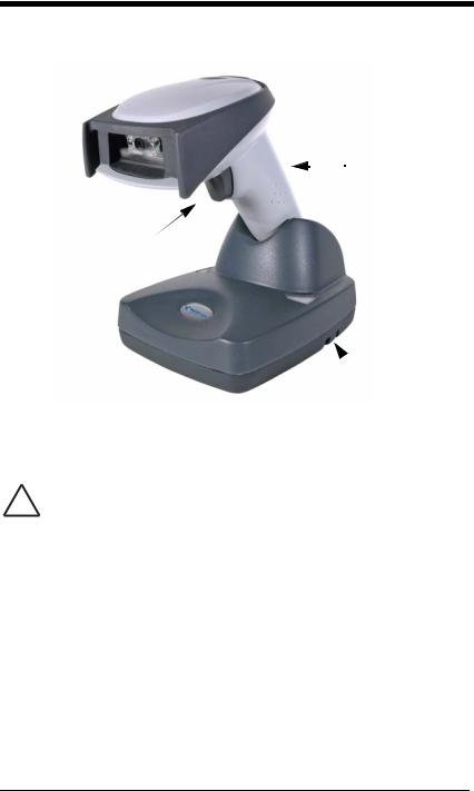
Cordless System: Main Components
Battery Contained
 in Handle
Image Scanner
2020 Base
About the Battery
We recommend use of Hand Held Products Li-ion battery backs. Use
!of any non-Hand Held Products battery may result in damage not covered by the warranty.
Power is supplied to the cordless image scanner by a rechargeable battery that is integrated in the image scanner handle. Each image scanner is shipped with a battery. (See Product Specifications beginning on page 13-1.)
Charging Information
The battery is designed to charge while the image scanner is positioned in the cordless base unit. Refer to "2020 LED Sequences and Meaning" on page 3-4 for an interpretation of the Charge Status indicators.
•Place the image scanner in the base that is connected to an appropriate power supply.
Battery Recommendations
•Batteries are shipped approximately 30% to 60% charged and should be fully charged for maximum charge capacity.
1 - 2

•The battery is a lithium ion cell and can be used without a full charge, and can also be charged without fully discharging, without impacting the battery life. There is no need to perform any charge/discharge conditioning on this type of battery.
•Do not disassemble the battery. There are no user-serviceable parts in the battery.
•Keep the base connected to power when the host is not in use.
•Replace a defective battery immediately since it could damage the image scanner.
•Don’t short-circuit a battery or throw it into a fire. It can explode and cause severe personal injury.
•Although your battery can be recharged many times, it will eventually be depleted. Replace it after the battery is unable to hold an adequate charge.
•If you are not sure if the battery or charger is working properly, send it to Honeywell International Inc. or an authorized service center for inspection. Refer to Customer Support on page 15-1 for additional information.
Proper Disposal of the Battery
When the battery has reached the end of its useful life, the battery should be disposed of by a qualified recycler or hazardous materials handler. Do not incinerate the battery or dispose of the battery with general waste materials. You may send the imager’s battery to us. (postage paid). The shipper is responsible for complying with all federal, state, and local laws and regulations related to the packing, labeling, manifesting, and shipping of spent batteries. Contact the Product
Service Department (page 15-2) for recycling or disposal information. Since you may find that your cost of returning the batteries significant, it may be more cost effective to locate a local recycle/disposal company.
Connecting the Base
A base can be connected between the keyboard and PC as a “keyboard wedge,” plugged into the serial port, plugged into a USB port, or connected to a portable data terminal in wand emulation or non decoded output mode.
Turn off power before connecting the base, then power up the computer once the base is fully connected. When the base is connected and powered up, put the image scanner in the base to establish a link. The green LED on the base flashes to indicate the image scanner’s battery is charging.
Connecting the Base with USB
A base can be connected to the USB port of a computer.
1 - 3
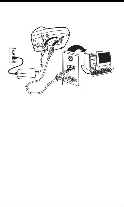
1.Connect the appropriate interface cable to the base first and then to the computer. Make sure the cables are secured in the wireways in the bottom of the base and that the base sits flat on a horizontal surface.
2.Program the base for the USB interface by scanning the appropriate programming barcode See page 2-5.
3.Verify the base operation by scanning a barcode from the Sample Symbols in the back of this manual.
For additional USB programming and technical information, refer to the Honeywell “USB Application Note,” available at www.honeywell.com/aidc.
Connecting the Base with Keyboard Wedge
1.Turn off power and disconnect the keyboard cable from the back of the terminal/computer.
1 - 4
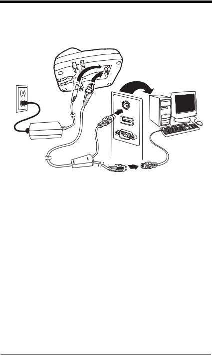
2.Connect the appropriate interface cable to the base and to the terminal/ computer and keyboard. Make sure the cables are secured in the wireways in the bottom of the base and that the base sits flat on a horizontal surface.
3.Turn the terminal/computer power back on.
4.Program the base for the keyboard wedge interface. See "Keyboard Wedge Connection" on page 2-1.
5.Verify the base operation by scanning a barcode from the Sample Symbols in the back of this manual.
1 - 5
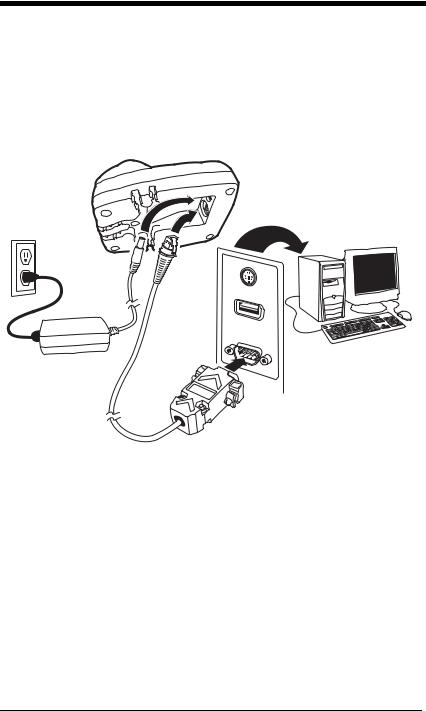
Connecting the Base with RS-232 Serial Port
1.Turn off power to the terminal/computer.
2.Connect the appropriate interface cable to the base. Make sure the cables are secured in the wireways in the bottom of the base and that the base sits flat on a horizontal surface.
Note: For the base to work properly, you must have the correct cable for your type of terminal/computer.
3.Plug the serial connector into the serial port on your computer. Tighten the two screws to secure the connector to the port.
4.Once the image scanner has been fully connected, power up the computer.
Connecting the Base with RS-232 Wedge
The 2020 uses TTL signal levels to wedge into an RS-232 serial network. Use only 2020 serial wedge cables to prevent damage to the base. Refer to RS-232 Baud Rate on page 2-16 to set the baud rate and communications protocol.
1.Turn off power to the computer.
2.Disconnect the existing serial cable from the computer.
1 - 6
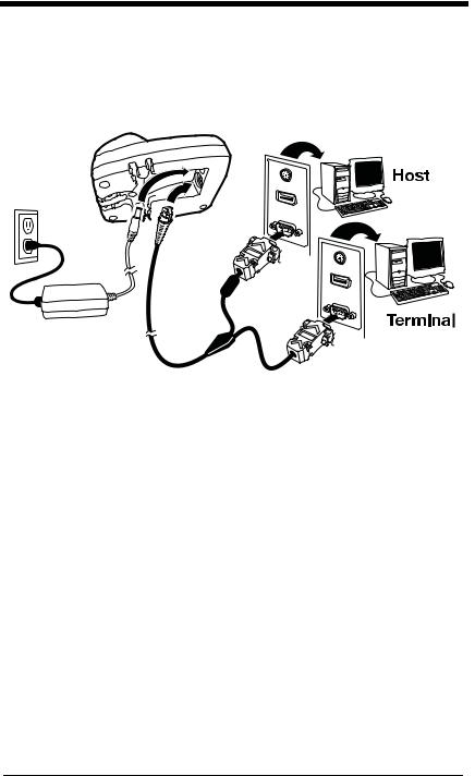
3.Connect the appropriate interface cable to the base. Make sure the cables are secured in the wireways in the bottom of the base and that the base sits flat on a horizontal surface.
Note: For the base to work properly, you must have the correct cable for your type of computer.
4.Plug the serial connector into the serial port on your computer. Tighten the two screws to secure the connector to the port.
5.Plug the other serial connector into the host connection and tighten the two screws.
6.Plug the power supply to the base and plug into the AC source.
7.Once the base has been fully connected, power up the computer.
Linking Image Scanner to Base
When newly shipped or defaulted to factory settings, the base and image scanner are not linked. Once the image scanner is placed into the base, the software automatically links the image scanner and the base. If the image scanner and base have previously been linked, you do not receive any feedback. If this
1 - 7

is the first time that the image scanner and base are linked, both devices emit a short chirp when their radios link. At this point, you are set to one image scanner to one base.
Image Scanner
Green LED |
|
Red LED |
2020 Base |
|
1.Provide power to the base.
2.Place the image scanner into the base. The image scanner and base link.
3.To determine if your cordless system is set up correctly, scan one of the sample barcodes in the back of this manual. If the image scanner provides a single good read beep and the green LED lights, the image scanner has successfully linked to the base. If you receive a triple error beep and the red LED lights, the image scanner has not linked to the base. Refer to page 14- 4 for troubleshooting information.
Communication Between the Cordless System
and the Host
The cordless image scanner provides immediate feedback in the form of a “good read” indication (a green LED on the image scanner and an audible beep) after a barcode is scanned correctly and the base has acknowledged receiving the data. This is possible since the cordless system provides two-way communication between the image scanner and the base.
1 - 8
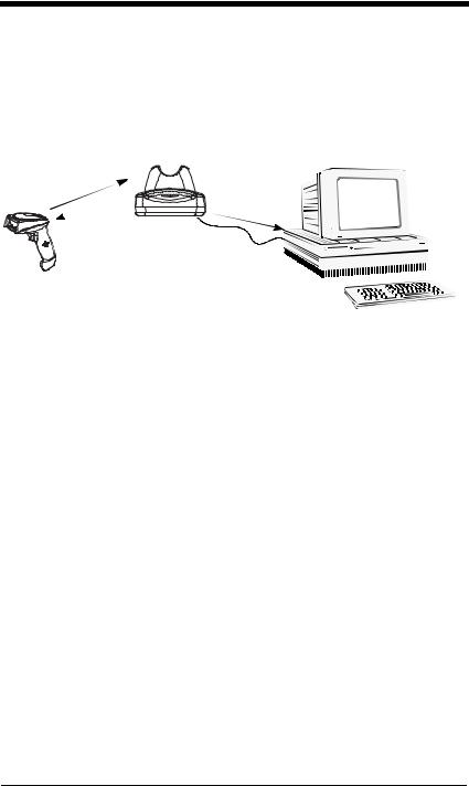
When data is scanned, the data is sent to the host system via the base unit. The cordless image scanner recognizes data acknowledgement (ACK) from the base unit. If it cannot be determined that the data has been properly sent to the base, the image scanner issues an error indication. You must then check to see if the scanned data was received by the host system.
1) Good Read
3) Base sends data to host
2) ACK from base
Reading Techniques
The image scanner has a view finder that projects a bright green aiming beam that corresponds to the image scanner’s horizontal field of view. The aiming beam should be centered over the barcode, but it can be positioned in any direction for a good read.
1 - 9
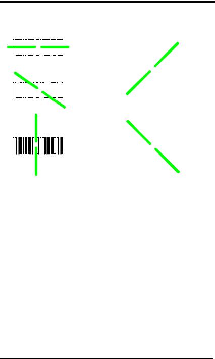
Linear barcode |
2D Matrix symbol |
|||||||||||||||||||||
|
|
|
|
|
|
|
|
|
|
|
|
|
|
|
|
|
|
|
|
|
|
|
|
|
|
|
|
|
|
|
|
|
|
|
|
|
|
|
|
|
|
|
|
|
|
|
|
|
|
|
|
|
|
|
|
|
|
|
|
|
|
|
|
|
|
|
|
|
|
|
|
|
|
|
|
|
|
|
|
|
|
|
|
|
|
|
|
|
|
|
|
|
|
|
|
|
|
|
|
|
|
|
|
|
|
|
|
|
|
|
|
|
|
|
The aiming beam is smaller when the image scanner is closer to the code and larger when it is farther from the code. Symbologies with smaller bars or elements (mil size) should be read closer to the unit. Symbologies with larger bars or elements (mil size) should be read farther from the unit. To read single or multiple symbols (on a page or on an object), hold the image scanner at an appropriate distance from the target, pull the trigger, and center the aiming beam on the symbol. If the code being scanned is highly reflective (e.g., laminated), it may be necessary to tilt the code up 15° to 18° to prevent unwanted reflection.
1 - 10
Loading...