


DRAFT COPY 11/11/11
Dolphin™ 7800
withWindows® Embedded Handheld 6.5
User’s Guide

DRAFT COPY 11/11/11
Disclaimer
Honeywell International Inc. (“HII”) reserves the right to make changes in specifications and other information contained in this document without prior notice, and the reader should in all cases consult HII to determine whether any such changes have been made. The information in this publication does not represent a commitment on the part of HII.
HII shall not be liable for technical or editorial errors or omissions contained herein; nor for incidental or consequential damages resulting from the furnishing, performance, or use of this material.
This document contains proprietary information that is protected by copyright. All rights are reserved. No part of this document may be photocopied, reproduced, or translated into another language without the prior written consent of HII.
Web Address: www.honeywellaidc.com
Trademarks
Dolphin, Dolphin RF, HomeBase, Mobile Base, ChargeBase, Net Base and QuadCharger are trademarks or registered trademarks of Hand Held Products, Inc. or Honeywell International Inc.
Microsoft, Windows, Windows Mobile, Windows Phone, Windows Embedded Handheld, Windows CE, Windows 98 Second Edition, Windows NT, Windows 2000, Windows ME, Windows XP, Windows 7, Windows Vista, ActiveSync, Outlook, and the Windows logo are trademarks or registered trademarks of Microsoft Corporation.
The Bluetooth trademarks are owned by Bluetooth SIG, Inc., U.S.A. and licensed to Honeywell.
Other product names mentioned in this manual may be trademarks or registered trademarks of their respective companies and are the property of their respective owners.
Patents
For patent information, please refer to www.honeywellaidc.com/patents.
©2011 Honeywell International Inc. All rights reserved.

DRAFT COPY 11/11/11
Table of Contents
Chapter 1 - Dolphin 7800 Terminal Agency Information
Laser Safety......................................................................................................................... |
1-1 |
Label Locations .............................................................................................................. |
1-1 |
Model Number, Serial Number and IMEI Labels............................................................ |
1-1 |
Laser Safety Label ......................................................................................................... |
1-1 |
Laser Safety Statement.................................................................................................. |
1-1 |
LED Safety........................................................................................................................... |
1-2 |
LED Safety Statement.................................................................................................... |
1-2 |
UL and C-UL Statement....................................................................................................... |
1-2 |
Approvals by Country........................................................................................................... |
1-2 |
R&TTE Compliance Statement—802.11a/b/g/n, Bluetooth, and/or GSM............................ |
1-3 |
Dolphin RF Terminal—802.11a/b/g/n, Bluetooth, and/or GSM ............................................ |
1-3 |
Canadian Compliance.......................................................................................................... |
1-4 |
Conformité à la règlementation canadienne ........................................................................ |
1-4 |
RF Exposure Information (SAR) .......................................................................................... |
1-4 |
For European Community Users ......................................................................................... |
1-5 |
Waste Electrical and Electronic Equipment Information ...................................................... |
1-5 |
China RoHS ......................................................................................................................... |
1-6 |
Pacemakers, Hearing Aids and Other Electrically Powered Devices .................................. |
1-6 |
Hearing Aid Compatibility (HAC).......................................................................................... |
1-6 |
Microwaves .......................................................................................................................... |
1-7 |
Chapter 2 - Getting Started |
|
Out of the Box ...................................................................................................................... |
2-1 |
Initial Setup for Dolphin 7800 Terminals .............................................................................. |
2-1 |
Replacing the Main Battery Pack......................................................................................... |
2-4 |
Home Screen ....................................................................................................................... |
2-5 |
Title Bar................................................................................................................................ |
2-5 |
Icons in the Title Bar ............................................................................................................ |
2-5 |
Horizontal Scroll................................................................................................................... |
2-8 |
Tile Bar................................................................................................................................. |
2-8 |
Pop-Up Menus ..................................................................................................................... |
2-8 |
Selecting Programs.............................................................................................................. |
2-8 |
File Explorer ......................................................................................................................... |
2-9 |
File Provisioning on the 7800............................................................................................. |
2-10 |
Search................................................................................................................................ |
2-10 |
Resetting the Terminal....................................................................................................... |
2-11 |
Soft Reset (Warm Boot) ............................................................................................... |
2-11 |
Hard Reset (Cold Boot)................................................................................................ |
2-11 |
Factory Reset............................................................................................................... |
2-11 |
Suspend Mode................................................................................................................... |
2-11 |
Chapter 3 - Hardware Overview |
|
Standard Configurations for the 7800 .................................................................................. |
3-1 |
Peripherals for the 7800....................................................................................................... |
3-3 |
iii

DRAFT COPY 11/11/11
Accessories for the 7800 ..................................................................................................... |
3-4 |
Front Panel: 7800................................................................................................................ |
3-5 |
Front Panel Features for the 7800................................................................................. |
3-6 |
Back Panel: 7800 ............................................................................................................... |
3-8 |
Back Panel Features for the 7800 ................................................................................. |
3-9 |
Bottom Panel: 7800 ........................................................................................................... |
3-10 |
I/O Connector .................................................................................................................... |
3-10 |
Using the Touch Panel ...................................................................................................... |
3-11 |
Installing a Screen Protector........................................................................................ |
3-11 |
Healthcare Housing........................................................................................................... |
3-11 |
Batteries ............................................................................................................................ |
3-12 |
Main Battery Pack........................................................................................................ |
3-12 |
Internal Backup Battery ............................................................................................... |
3-14 |
Managing Battery Power ............................................................................................. |
3-14 |
Checking Battery Power .............................................................................................. |
3-15 |
System Resets .................................................................................................................. |
3-15 |
Installing a SIM Card and/or Memory Card ....................................................................... |
3-16 |
Installation.................................................................................................................... |
3-16 |
Chapter 4 - Using the Scan Image Engine |
|
Overview.............................................................................................................................. |
4-1 |
Laser Safety ........................................................................................................................ |
4-1 |
N5603 Beam Divergence Angle .................................................................................... |
4-1 |
LED Safety .......................................................................................................................... |
4-1 |
Image Engine Specifications ............................................................................................... |
4-1 |
Depth of Field ................................................................................................................ |
4-1 |
Supported Bar Code Symbologies ..................................................................................... |
4-3 |
Decoding ............................................................................................................................. |
4-4 |
To Decode a Bar Code.................................................................................................. |
4-4 |
Aiming Beam Options .................................................................................................... |
4-5 |
Capturing Images ................................................................................................................ |
4-6 |
Taking an Image............................................................................................................ |
4-6 |
Uploading Images.......................................................................................................... |
4-7 |
Chapter 5 - Using the Color Camera |
|
Overview.............................................................................................................................. |
5-1 |
Taking a picture using the Camera Demo tool .................................................................... |
5-1 |
Taking a picture using the Windows Embedded Handheld 6.5 Camera tool ...................... |
5-2 |
Recording Video .................................................................................................................. |
5-3 |
Uploading Pictures and Videos...................................................................................... |
5-4 |
Chapter 6 - Using the Keyboards |
|
Available Keyboards............................................................................................................ |
6-1 |
Keyboard Combinations ................................................................................................ |
6-2 |
Common Buttons ........................................................................................................... |
6-2 |
Using the Function Keys...................................................................................................... |
6-2 |
Using the Modifier Keys ...................................................................................................... |
6-3 |
iv

DRAFT COPY 11/11/11
Using the Navigation Keys .................................................................................................. |
6-3 |
30-Key Numeric Keyboard .................................................................................................. |
6-4 |
30-Key Numeric Keyboard Combinations...................................................................... |
6-4 |
30-Key Numeric (Calculator) Keyboard............................................................................... |
6-6 |
30-Key Numeric (Calculator) Keyboard Combinations.................................................. |
6-6 |
46-Key QWERTY Keyboard ................................................................................................ |
6-8 |
46-Key QWERTY Keyboard Combinations ................................................................... |
6-8 |
46-Key AZERTY Keyboard................................................................................................ |
6-11 |
46-Key AZERTY Keyboard Combinations................................................................... |
6-11 |
46-Key QWERTZ Keyboard .............................................................................................. |
6-14 |
46-Key QWERTZ Keyboard Combinations ................................................................. |
6-14 |
Chapter 7 - System Settings |
|
Overview.............................................................................................................................. |
7-1 |
Clock & Alarms .................................................................................................................... |
7-2 |
Personal Menu .................................................................................................................... |
7-3 |
Buttons........................................................................................................................... |
7-3 |
System Menu....................................................................................................................... |
7-7 |
About ............................................................................................................................. |
7-8 |
Backlight ........................................................................................................................ |
7-9 |
Battery ......................................................................................................................... |
7-10 |
Certificates................................................................................................................... |
7-10 |
Encryption.................................................................................................................... |
7-11 |
Error Reporting ............................................................................................................ |
7-11 |
External GPS ............................................................................................................... |
7-11 |
Five Volt Control .......................................................................................................... |
7-12 |
Smart Sensor............................................................................................................... |
7-12 |
Managed Programs ..................................................................................................... |
7-13 |
Memory........................................................................................................................ |
7-14 |
RIL ............................................................................................................................... |
7-15 |
Power........................................................................................................................... |
7-15 |
Regional Settings......................................................................................................... |
7-15 |
Remove Programs....................................................................................................... |
7-16 |
Screen ............................................................................................................................... |
7-17 |
Task Manager.................................................................................................................... |
7-18 |
Chapter 8 - Communication |
|
Connections Menu............................................................................................................... |
8-1 |
Connections Manager ......................................................................................................... |
8-2 |
To Access the Connections Manager............................................................................ |
8-2 |
Tasks ............................................................................................................................. |
8-2 |
Advanced....................................................................................................................... |
8-3 |
Dolphin Wireless Manager .................................................................................................. |
8-4 |
Dolphin Wireless Manager Window............................................................................... |
8-4 |
Enabling the Radios....................................................................................................... |
8-4 |
Accessing Radio Configuration Utilities ......................................................................... |
8-5 |
Network Cards..................................................................................................................... |
8-6 |
Connecting and Synchronizing the Terminal and Workstation............................................ |
8-6 |
v

DRAFT COPY 11/11/11
Installing Additional Software .............................................................................................. |
8-8 |
Adding Programs Using ActiveSync or Windows Mobile Device Center....................... |
8-8 |
Connecting the Terminal to a Wireless Network.......................................................... |
8-10 |
Adding Programs Using the Internet............................................................................ |
8-10 |
Software Upgrades............................................................................................................ |
8-10 |
7800 COM Port Assignment Table.................................................................................... |
8-11 |
Chapter 9 - Working with Wireless Wide Area Networking (WWAN) |
|
Overview.............................................................................................................................. |
9-1 |
Antenna Band................................................................................................................ |
9-1 |
Enabling the WWAN Radio ................................................................................................. |
9-3 |
GSM/HSPA+ Global Radio Dolphin Models........................................................................ |
9-3 |
Voice Communication.................................................................................................... |
9-3 |
Audio Modes.................................................................................................................. |
9-3 |
Volume Control .............................................................................................................. |
9-4 |
Accessing the Dialer Window ........................................................................................ |
9-4 |
Dialing............................................................................................................................ |
9-4 |
Sending Calls................................................................................................................. |
9-5 |
Ending Calls................................................................................................................... |
9-5 |
Accessing Voice Mail..................................................................................................... |
9-5 |
View Options.................................................................................................................. |
9-5 |
Setup Options...................................................................................................................... |
9-5 |
Data Communication (GSM/HSPA+ Global Radio Dolphin Models)................................... |
9-7 |
System Requirements ................................................................................................... |
9-7 |
Information Requirements ............................................................................................. |
9-7 |
Establishing Data Communication................................................................................. |
9-7 |
Manual Network Selection ........................................................................................... |
9-10 |
Data Communication GSM/CDMA Dolphin Models .......................................................... |
9-11 |
Gobi Manager.............................................................................................................. |
9-11 |
Establishing Data Communication............................................................................... |
9-12 |
Chapter 10 - Working with the Bluetooth Radio |
|
Enabling the Bluetooth Radio ............................................................................................ |
10-1 |
Pairing and Trusted Devices ............................................................................................. |
10-2 |
Connecting to Other Bluetooth Devices ............................................................................ |
10-2 |
Transferring Files............................................................................................................... |
10-5 |
Making the Terminal Discoverable .................................................................................... |
10-6 |
Enabling the Terminal to Receive Incoming Beams .................................................... |
10-6 |
Selecting COM Ports ......................................................................................................... |
10-7 |
Chapter 11 - Working with GPS |
|
Overview............................................................................................................................ |
11-1 |
Assisted GPS Support....................................................................................................... |
11-1 |
Powering the GPS Module ................................................................................................ |
11-1 |
vi

DRAFT COPY 11/11/11
Communication Ports ........................................................................................................ |
11-1 |
Selecting the Port ........................................................................................................ |
11-1 |
COM7 .......................................................................................................................... |
11-1 |
GPS Intermediate Driver.............................................................................................. |
11-2 |
GPS Demo ........................................................................................................................ |
11-2 |
Chapter 12 - Dolphin 7800 HomeBase Device (Model 7800-HB) |
|
Overview............................................................................................................................ |
12-1 |
Parts and Functions........................................................................................................... |
12-2 |
Back Panel .................................................................................................................. |
12-3 |
Bottom Panel ............................................................................................................... |
12-4 |
Power ................................................................................................................................ |
12-4 |
Connecting Power to the HomeBase........................................................................... |
12-4 |
Charging the Main Battery................................................................................................. |
12-5 |
To Power a Terminal and Charge its Main Battery...................................................... |
12-5 |
Charging a Spare Battery in the Auxiliary Battery Well ............................................... |
12-5 |
Communication.................................................................................................................. |
12-6 |
Connecting the Communication Cables ...................................................................... |
12-6 |
Establishing Communication ....................................................................................... |
12-6 |
Communicating with the Dolphin Terminal .................................................................. |
12-6 |
Mounting the HomeBase ................................................................................................... |
12-7 |
Chapter 13 - Dolphin 7800 eBase Device (Model 7800-EHB) |
|
Overview............................................................................................................................ |
13-1 |
Unpacking the eBase................................................................................................... |
13-1 |
Parts and Functions........................................................................................................... |
13-2 |
Front Panel .................................................................................................................. |
13-2 |
Back Panel .................................................................................................................. |
13-3 |
Bottom Panel ............................................................................................................... |
13-4 |
Power ................................................................................................................................ |
13-4 |
Connecting Power to the eBase .................................................................................. |
13-5 |
Charging the Main Battery................................................................................................. |
13-5 |
To Power a Terminal and Charge its Main Battery...................................................... |
13-5 |
Charging a Spare Battery in the Auxiliary Battery Well ............................................... |
13-5 |
Communication.................................................................................................................. |
13-6 |
Software Requirements ............................................................................................... |
13-6 |
Establishing Ethernet Communication......................................................................... |
13-6 |
Establishing USB Communication ............................................................................... |
13-7 |
Mounting the eBase........................................................................................................... |
13-7 |
Optional Hardware Mount............................................................................................ |
13-8 |
Chapter 14 - Dolphin 7800 Mobile Base Device (Model 7800-MB) |
|
Overview............................................................................................................................ |
14-1 |
Mobile Base Components ................................................................................................ |
14-2 |
Back Panel and Mounting Brackets................................................................................... |
14-3 |
vii

DRAFT COPY 11/11/11
Mounting............................................................................................................................ |
14-3 |
Safety Precautions....................................................................................................... |
14-3 |
Installation.................................................................................................................... |
14-4 |
Charging the Main Battery................................................................................................. |
14-4 |
To Power a Terminal and Charge its Main Battery...................................................... |
14-4 |
Chapter 15 - Dolphin 7800 ChargeBase Device (Model 7800-CB) |
|
Overview............................................................................................................................ |
15-1 |
Unpacking the ChargeBase......................................................................................... |
15-1 |
Parts and Functions........................................................................................................... |
15-2 |
Front Panel .................................................................................................................. |
15-2 |
Back Panel................................................................................................................... |
15-3 |
Power ................................................................................................................................ |
15-3 |
Connecting Power to the ChargeBase ............................................................................. |
15-3 |
Charging the Main Battery................................................................................................. |
15-4 |
To Power a Terminal and Charge its Main Battery...................................................... |
15-4 |
Mounting the ChargeBase................................................................................................. |
15-4 |
Chapter 16 - Dolphin 7800 Net Base Device (Model 7800-NB) |
|
Overview............................................................................................................................ |
16-1 |
Parts and Functions........................................................................................................... |
16-2 |
Front Panel .................................................................................................................. |
16-2 |
Back Panel .................................................................................................................. |
16-3 |
Bottom Panel ............................................................................................................... |
16-4 |
Power ................................................................................................................................ |
16-4 |
Connecting Power to the Net Base.............................................................................. |
16-4 |
Charging the Main Battery................................................................................................. |
16-5 |
To Power a Terminal and Charge its Main Battery...................................................... |
16-5 |
Communication.................................................................................................................. |
16-5 |
Software Requirements ............................................................................................... |
16-5 |
Connecting the Dolphin Terminal to the Net Base ............................................................ |
16-6 |
Mounting the Net Base ...................................................................................................... |
16-6 |
Chapter 17 - Dolphin 7800 QuadCharger Device (Model 7800-QC) |
|
Overview............................................................................................................................ |
17-1 |
Parts and Functions........................................................................................................... |
17-2 |
Power ................................................................................................................................ |
17-3 |
Inserting and Charging Batteries ....................................................................................... |
17-3 |
Mounting the QuadCharger ............................................................................................... |
17-4 |
Troubleshooting................................................................................................................. |
17-5 |
Chapter 18 - Customer Support |
|
Product Service and Repair............................................................................................... |
18-1 |
Online Product Service and Repair Assistance ........................................................... |
18-1 |
Technical Assistance......................................................................................................... |
18-2 |
Online Technical Assistance........................................................................................ |
18-2 |
viii

DRAFT COPY 11/11/11
Limited Warranty ............................................................................................................... |
18-3 |
How to Extend Your Warranty ..................................................................................... |
18-4 |
ix

DRAFT COPY 11/11/11
x
1 DRAFT COPY 11/11/11
Dolphin 7800Terminal Agency Information
Dolphin 7800 mobile computers meet or exceed the requirements of all applicable standards organizations for safe operation. However, as with any electrical equipment, the best way to ensure safe operation is to operate them according to the agency guidelines that follow. Read these guidelines carefully before using your Dolphin terminal.
This documentation is relevant for the following Dolphin models: 7800L0, 7800LW, 7800LG, 7800LC.
Laser Safety
Label Locations
7800 Back Panel
Compliance Label
Model Number, Serial Number and IMEI Labels
The model (item) number, serial number, and international mobile equipment identity (IMEI) number for the terminal are located on labels affixed to the walls of the battery well.
Laser Safety Label
If the following label is attached to your product, it indicates the product contains an engine with a laser aimer:
Image Engines with Integrated Laser Aimers
Laser Safety Statement
This device has been tested in accordance with and complies with IEC60825-1(Ed. 2.0), EN60825- 1:2007. Complies with 21 CFR 1040.10 and 1040.11, except for deviations pursuant to Laser Notice No. 50, dated June 24, 2007. LASER LIGHT, DO NOT STARE INTO BEAM. CLASS 2 LASER PRODUCT, 1.0 mW MAX OUTPUT: 650nm.
WARNING - Use of controls or adjustments or performance of procedures other than those specified herein ! may result in hazardous radiation exposure.
1 - 1

DRAFT COPY 11/11/11
LED Safety
LED Safety Statement
LEDs have been tested and classified as “EXEMPT RISK GROUP” to the Standard: IEC 62471:2006.
!CAUTION! Do not view directly with optical instruments.
UL and C-UL Statement
UL and C-UL listed: UL60950-1 2nd Edition, and CSA C22.2 No. 60950-1-07 2nd Edition.
Approvals by Country
Country |
EMC, Radio, & SAR |
Safety |
|
|
|
U.S.A. |
FCC Part 15, Subpart B |
UL60950-1 2nd Edition |
|
FCC Part 15, Subpart C, 15.247 |
|
|
FCC Part 15, Subpart E |
|
|
FCC Part 22H |
|
|
FCC Part 24E |
|
|
FCC SAR OET 65 Supplement C |
|
|
|
|
Canada |
ICES-003 (Class B) |
CSA C22.2 No. 60950-1-07, |
|
RSS 132 |
2nd Edition |
|
RSS 133 |
|
|
RSS 210 |
|
|
|
|
European Community/CE |
EN300328, EN301893, EN55022, |
EN60950-1 2nd Edition |
|
EN55024, EN301489-1, |
EN60825-1 2nd Edition |
|
EN301489-7/24, EN301489-17, |
|
|
3GPPTS 51.010-1, EN301511, |
|
|
EN301908, EN50360, EN50361, |
|
|
EN50371, EN50392, IEC6220-1, |
|
|
IEC6220-2, EN300440, 301 389-25 |
|
|
(CDMA 2000) |
|
|
|
|
International |
|
IEC 60950-1 2nd Edition |
|
|
IEC 60825-1 2nd Edition |
|
|
IEC 62471 |
|
|
|
R&TTE Compliance Statement—802.11a/b/g/n, Bluetooth, and/or GSM
Dolphin RF terminals are in conformity with all essential requirements of the R&TTE Directive (1999/5/ EC).
This product is marked with  according to article 12 of the R&TTE Directive. In addition, this product complies to 2006/95/EC Low Voltage Directive when supplied with the recommended power supply. Honeywell shall not be liable for use of our product with equipment (i.e., power supplies, personal computers, etc.) that is not CE marked and does not comply with the Low Voltage Directive.
1 - 2

DRAFT COPY 11/11/11
The equipment is intended for use throughout the European Community; PAN European Frequency Range: 2.402–2.480 GHz. Restrictions for use in France are as follows:
•Indoor use: Maximum power (EIRP*) of 100 mW for the entire 2.400–2.4835 GHz
•Outdoor use: Maximum power (EIRP*) of 100 mW for the 2.400–2.454 GHz band & maximum power (EIRP*) of 10 mW for the 2.454–2.483 MGHz band.
•5Ghz band: UNII (Unlicensed National Information Infrastructure) or band1 (5.150 to 5.250 GHz) is restricted to indoor use only. Any other use will make the operation of the device illegal.
For further information, please contact:
Honeywell Imaging & Mobility Europe BV
Nijverheidsweg 9
5627 BT Eindhoven
The Netherlands
FCC Requirements
Dolphin RF Terminal—802.11a/b/g/n, Bluetooth, and/or GSM
This device complies with Part 15 of the FCC Rules. Operation is subject to the following two conditions:
(1) this device may not cause harmful interference, and (2) this device must accept any interference received, including interference that may cause undesired operation.
This equipment has been tested and found to comply with the limits for a Class B digital device pursuant to Part 15 of the FCC Rules. These limits are designed to provide reasonable protection against harmful interference in a residential installation. This equipment generates, uses, and can radiate radio frequency energy and, if not installed and used in accordance with the instructions, may cause harmful interference to radio communications. However, there is no guarantee that interference will not occur in a particular installation. If this equipment does cause harmful interference to radio or television reception, which can be determined by turning the equipment off and on, the user is encouraged to try to correct the interference by one or more of the following measures:
•Reorient or relocate the receiving antenna.
•Increase the separation between the equipment and receiver.
•Connect the equipment into an outlet on a circuit different from that to which the receiver is connected.
•Consult the dealer or an experienced radio/TV technician for help.
If necessary, the user should consult the dealer or an experienced radio/television technician for additional suggestions. The user may find the following booklet helpful: “Something About Interference.” This is available at FCC local regional offices. Our company is not responsible for any radio or television interference caused by unauthorized modifications of this equipment or the substitution or attachment of connecting cables and equipment other than those specified by our company. The correction is the responsibility of the user. Use only shielded data cables with this system.
In accordance with FCC 15.21, changes or modifications not expressly approved by the party responsible for compliance could void the user’s authority to operate the equipment.
The antenna(s) used for this transmitter must not be co-located or operating in conjunction with any other antenna or transmitter.
CAUTION! - Any changes or modifications not expressly approved by the grantee of this device could void the user’s authority to operate the equipment.
1 - 3

DRAFT COPY 11/11/11
Canadian Compliance
This device complies with Industry Canada license-exempt RSS standard(s). Operation is subject to the following two conditions:
(1)this device may not cause interference, and
(2)this device must accept any interference, including interference that may cause undesired operation of the device.
This Class B digital apparatus complies with Canadian ICES-003.
This Category II radiocommunication device complies with Industry Canada Standard RSS-310.
Conformité à la règlementation canadienne
Le présent appareil est conforme aux CNR d'Industrie Canada applicables aux appareils radio exempts de licence. L'exploitation est autorisée aux deux conditions suivantes:
(1)l'appareil ne doit pas produire de brouillage, et
(2)l'utilisateur de l'appareil doit accepter tout brouillage radioélectrique subi, même si le brouillage est susceptible d'en compromettre le fonctionnement."
Cet appareil numérique de la classe B est conforme à la norme NMB-003 du Canada.
Ce dispositif de radiocommunication de catégorie II respecte la norme CNR-310 d’Industrie Canada.
RF Exposure Information (SAR)
This mobile phone meets the government's requirements for exposure to radio waves. This phone is designed and manufactured not to exceed the emission limits for exposure to radio frequency (RF) energy set by the Federal Communications Commission of the U.S. Government.
The exposure standard for wireless mobile phones employs a unit of measurement known as the Specific Absorption Rate, or SAR. The SAR limit set by the FCC is 1.6W/kg. Tests for SAR are conducted using standard operating positions accepted by the FCC with the phone transmitting at its highest certified power level in all tested frequency bands. Although the SAR is determined at the highest certified power level, the actual SAR level of the phone while operating can be well below the maximum value. This is because the phone is designed to operate at multiple power levels so as to use only the poser required to reach the network. In general, the closer you are to a wireless base station antenna, the lower the power output.
The highest SAR value for the model phone as reported to the FCC when tested for use at the ear is NA W/kg Max. and when worn on the body, as described in this user guide, is 0.083 W/kg Max. (Bodyworn measurements differ among phone models, depending upon available accessories and FCC requirements.)
While there may be differences between the SAR levels of various phones and at various positions, they all meet the government requirement.
The FCC has granted an Equipment Authorization for this model phone with all reported SAR levels evaluated as in compliance with the FCC RF exposure guidelines. SAR information on this model phone is on file with the FCC and can be found under the Display Grant section of www.fcc.gov/oet/ea/fccid after searching on FCC ID: HD57800L0.
For body worn operation, this phone has been tested and meets the FCC RF exposure guidelines for use with an accessory that contains no metal and positions the handset a minimum of 1.5 cm from the body. Use of other accessories may not ensure compliance with FCC RF exposure guidelines. If you do not use a body-worn accessory and are not holding the phone at the ear, position the handset a minimum of 1.5 cm from your body when the phone is switched on.
1 - 4

DRAFT COPY 11/11/11
For European Community Users
Honeywell complies with Directive 2002/96/EC OF THE EUROPEAN PARLIAMENT AND OF THE COUNCIL of 27 January 2003 on waste electrical and electronic equipment (WEEE); European REACH Regulation 1907/2006 of 1 June, 2007, and Restriction of Hazardous Substances Directive (RoHS) 2002/95/EC of 1 July 2006.
Waste Electrical and Electronic Equipment Information
This product has required the extraction and use of natural resources for its production. It may contain hazardous substances that could impact health and the environment, if not properly disposed.
In order to avoid the dissemination of those substances in our environment and to diminish the pressure on the natural resources, we encourage you to use the appropriate take-back systems for product disposal. Those systems will reuse or recycle most of the materials of the product you are disposing in a sound way.
The crossed out wheeled bin symbol informs you that the product should not be disposed of along with municipal waste and invites you to use the appropriate separate take-back systems for product disposal. If you need more information on the collection, reuse, and recycling systems, please contact your local or regional waste administration. You may also contact your supplier for more information on the environmental performances of this product.
China RoHS
|
|
|
|
|
|
|
|
|
|
|
|
|
|
|
|
|
|
|
|
|
|
|
|
|
|
|
|
|
|
|
|
|
|
|
|
|
|
|
|
|
|
|
|
|
|
|
|
|
|
|
|
|
|
|
|
|
|
|
(Parts Name) |
|
|
(Toxic and Hazardous Substances or Elements) |
|
|
|||||||
|
|
|
|
|
|
|
|
|
|
|
|
|
|
|
|
|
|
|
|
|
|
|
|
|
|
(Pb) |
|
(Hg) |
|
|
(Cd) |
|
(Cr6+) |
(PBB) |
(PBDE) |
|
|
|
|
|
|
|
(Imager) |
x |
|
o |
|
|
o |
|
o |
o |
o |
|
|
|
|
|
|
|
|
|
|
|
|
|
|
|
|
|
|
|
|
|
|
|
|
(PCBA) |
x |
|
o |
|
|
o |
|
o |
o |
o |
|
|
|
|
|
|
|
|
|
|
|
|
|
|
|
|
|
|
|
|
|
|
|
|
|
|
(Housing) |
x |
|
o |
|
|
o |
|
o |
o |
o |
|
|
|
|
|
|
|
|
|
|
|
|
|
|
|
|||
|
|
|
(Cables) |
|
o |
|
o |
|
|
o |
|
o |
o |
o |
|||
|
|
|
|
|
|
|
|
|
|
|
|
|
|
|
|
|
|
|
|
|
|
|
|
(LCD) |
o |
|
o |
|
|
o |
|
o |
o |
o |
|
|
|
|
|
|
|
|
|
|
|
|
|
|
|||||
|
|
(LCD Frame) |
o |
|
o |
|
|
o |
|
o |
o |
o |
|||||
|
|
|
|
|
|
|
|
|
|
|
|
|
|
|
|
||
|
|
|
|
|
(Camera) |
x |
|
o |
|
|
o |
|
o |
o |
o |
||
|
|
|
|
|
|
|
|
|
|
|
|
|
|
|
|
|
|
|
|
|
(Keypad) |
|
o |
|
|
|
|
|
|
|
|
|
|||
|
|
|
|
|
|
|
|
|
|
|
|
|
|
|
|
||
|
|
|
|
|
|
o |
|
o |
|
|
o |
|
o |
o |
o |
||
|
|
|
(Battery) |
|
|
|
|
|
|
|
|
|
|
|
|||
|
|
|
|
(Power Adapter) |
x |
|
o |
|
|
o |
|
o |
o |
o |
|||
|
|
|
|
|
|
|
|
|
|
|
|
|
|||||
o: |
|
|
|
|
|
|
|
SJ/T11363-2006 |
|
|
|
(Indicates that this toxic or hazardous substance contained in all of the homogeneous |
|||||
|
|
|
|
|
|
|
|
|
|
|
|
|
|
|
|
||
materials for this part is below the limit requirement in China’s SJ/T11363-2006.) |
|
|
|
|
|
|
|||||||||||
x: |
|
|
SJ/T11363-2006 |
|
|
(Indicates that this toxic or hazardous substance contained in at least one of the |
|||||||||||
homogeneous materials for this part is above the limit requirement in China’s SJ/T11363-2006. ) |
|
|
|
|
|||||||||||||
|
|
|
|
|
|
|
|
|
|
|
|
|
|||||
|
|
|
|
|
|
|
|
|
|
|
|
||||||
|
|
|
|
|
|
|
|
|
|
|
|
|
|
|
|
||
Pacemakers, Hearing Aids and Other Electrically Powered Devices |
|
||||||||||||||||
|
|
|
|
|
|
|
|
|
|
|
|
|
|
|
|
|
|
Most manufacturers of medical devices adhere to the IEC 601-1-2 standard. This standard requires |
|||||||||||||||||
|
|
|
|
|
|
|
|
|
|
|
|
|
|
|
|
||
devices to operate properly in an EM Field with a strength of 3V/m over a frequency range of 26 to |
|||||||||||||||||
|
|
|
|
|
|
|
|
|
|
|
|
|
|
|
|
|
|
1000MHz. The maximum allowable field strength emitted by the Dolphin terminal is 0.3V/m according to |
|||||||||||||||||
|
|
|
|
|
|
|
|
|
|
|
|
|
|
|
|||
Subpart B of Part 1 of the FCC rules. Therefore, the RF from the Dolphin terminal has no effect on |
|||||||||||||||||
|
|
|
|
|
|
|
|
|
|
|
|
|
|
|
|||
medical devices that meet the IEC specification. |
|
|
|
|
|||||||||||||
|
|
|
|
|
|
|
|
|
|
|
|
||||||
1 - 5

DRAFT COPY 11/11/11
Hearing Aid Compatibility (HAC)
The Dolphin 7800 has been tested for hearing aid compatibility. This device has an M3 and T3 rating. For additional HAC information, including the HAC rating for this product, please refer to www.honeywellaidc.com.
When some wireless devices are used near some hearing devices such as hearing aids and implants, users may detect a buzzing or humming noise. Some hearing devices are more immune than others to this interference noise. Wireless devices may also vary in the amount of interference they generate.
The ratings for compatibility of digital wireless devices with hearing aids are described in the American National Standards Institute (ANSI) C63.19 standard:
M-Rating: Phones rated M3 or M4 meet FCC requirements and are likely to generate less interference with hearing devices than phones that are not labeled. M4 is the superior/higher of the two ratings.
T-Rating: Phones rated T3 or T4 meet FCC requirements and are likely to be more usable with hearing devices' telecoil than unrated phones. T4 is the superior/higher of the two ratings.
The more immune the hearing aid device is, the less likely one is to experience interference noise from the wireless phone. Hearing aid devices may also be rated. Adding the ratings of the hearing aid and the phone would determine probable usability:
•Any combined rating equal to or greater than six offers the best use.
•Any combined rating equal to five is considered normal use.
The ratings are not guarantees. Results will vary depending on the user's hearing device and hearing loss. If your hearing device happens to be vulnerable to interference, you may not be able to use this device successfully. Trying out this device with your hearing device is the best way to evaluate it for your personal needs.
This device has been tested and rated for use with hearing aids for some of the wireless technologies that it utilizes. However, there may be some newer wireless technologies used in this phone that have not been tested yet for use with hearing aids. It is important to try the different features of this phone thoroughly and in different locations, using your hearing aid or cochlear implant, to determine if you hear any interfering noise. Consult your service provider or the manufacturer of this phone for information on hearing aid compatibility.
Microwaves
The radio in the Dolphin RF terminal operates on the same frequency band as a microwave oven. Therefore, if you use a microwave within range of the Dolphin RF terminal you may notice performance degradation in your wireless network. However, both your microwave and your wireless network will continue to function.
1 - 6

2 |
DRAFT COPY 11/11/11 |
|
Getting Started |
Out of the Box
Verify that the carton contains the following items:
•Dolphin mobile computer (the terminal)
•Main battery pack
•Quick Start Guide
If you ordered accessories for your terminals, verify that they are also included with the order. Be sure to keep the original packaging in the event that the Dolphin terminal should need to be returned for service. For details, see Product Service and Repair on page 18-1.
Initial Setup for Dolphin 7800 Terminals
Step 1. Release the Hand Strap
Step 2. Install the Main Battery Pack
Note: Before installing the main battery pack, read the Guidelines for Battery Pack Use and Disposal on page 3-13.
Dolphin 7800 model terminals are designed for use with standard battery pack model 7800-BTSC (Li-ion 3.7 V, 8.9 watt hour) and extended battery pack models 7800-BTXC and 7800-BTXCW (Li-ion 3.7 V, 14.8 watt hour) manufactured for Honeywell International Inc.
The terminal is shipped with the battery packaged separate from the unit. Perform the steps illustrated below to install the main battery. For information on how to remove the battery, see Replacing the Main Battery Pack on page 2-4.
Note: The terminal does not power ON unless the battery is locked  .
.
Ensure all components are dry prior to placing the battery in the terminal. Mating wet components may cause ! damage not covered by the warranty.
|
|
1 |
4 |
|
|
2 |
3 |
|
|
|
|
|
||
|
|
|
|
|
|
|
|
|
|
2 - 1
DRAFT COPY 11/11/11
Step 3. Charge the Main and Backup Batteries
The power supply for Dolphin terminals consists of two types of battery power: the main battery pack that is accessible from the back panel, and the backup battery that resides inside the terminal. The main battery powers the terminal. The internal backup battery charges off the main battery and maintains the application data stored in RAM memory for up to 5 minutes when the terminal’s main battery pack is completely discharged or removed.
Dolphin 7800 terminals are designed for use with the following 7800 charging devices and cables: 7800-HB, 7800-EHB, 7800-NB, 7800-CB, 7800-DEX, 7800-MC, 7800-MB, 7800-USB, and 7800-USBH. See Chapters 12-17 for additional information on the individual device requirements.
Before Initial Use
Terminals are shipped with both batteries discharged of all power. The initial charging time for the main battery pack is 4 hours for the standard battery pack or 6 hours for the extended battery pack. Connect the terminal to one of the 7800 series charging peripherals to charge; see Peripherals for the 7800 on page 3-3.
Note: Honeywell recommends charging the Dolphin terminal for at least 24 hours prior to initial use to ensure the internal backup battery is fully charged.
We recommend use of Honeywell peripherals, power cables, and power adapters. Use of any non-Honeywell
!peripherals, cables, or power adapters may cause damage not covered by the warranty.
Charging Using the Communication Cable
Ensure all components are dry prior to mating terminals/batteries with peripheral devices. Mating wet ! components may cause damage not covered by the warranty.
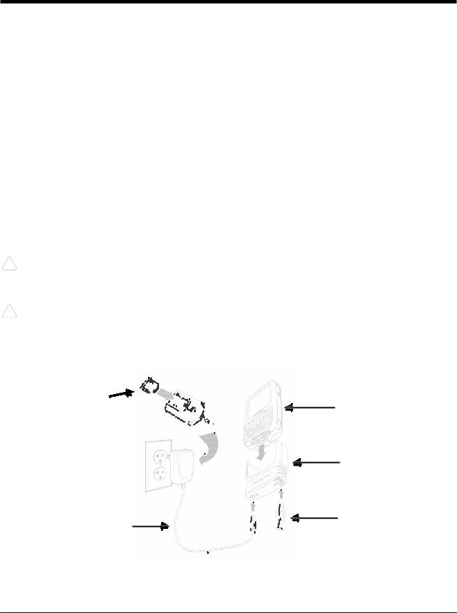
Client Device Communication Cable (7800-USB)
Use only a UL Listed power supply, which has been qualified by Honeywell with an output rated at 5VDC and 3A with the device.
3 |
Dolphin 7800 Models |
|
1
Charging Cup
4 2
Power Cable
2 - 2
DRAFT COPY 11/11/11
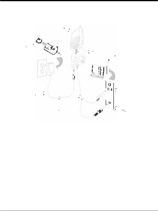
Host Device Communication Cable (7800-USBH, 7800-DEX)
Use only a UL Listed power supply, which has been qualified by Honeywell with an output rated at 5VDC and 3A with the device.
|
|
|
|
|
|
|
|
|
|
|
|
|
|
|
|
|
|
|
|
Dolphin 7800 |
|||||||||||||||||||||||||||||||||||||||||||||||||||||||||||||||||||||||||||||
4 |
|
|
|
|
|
|
|
|
|
|
|
|
|
|
|
|
|
|
|
|
|
|
|
|
|
|
|
|
|
|
|
|
|
|
|
|
|
|
|
|
|
|
|
|
|
|
|
|
|
|
|
|
|
|
|
|
|
|
|
|
|
|
|
|
|
|
|
|
|
|
|
|
|
|
|
|
|
|
|
|
|
|
|
|
|
||||||||||||
|
|
|
|
|
|
|
|
|
|
|
|
|
|
|
|
|
|
|
|
|
|
|
|
|
|
|
|
|
|
|
|
|
|
|
|
|
|
|
|
|
|
|
|
|
|
|
|
|
|
|
|
|
|
|
|
|
|
|
|
|
|
|
|
|
|
|
|
|
|
|
|
|
|
|
|
|
|
|
|
|
|
|
|
|
|||||||||||||
Plug Adapter |
|
|
|
|
|
|
|
|
|
|
|
|
|
|
1 |
|
|
Cable Cup |
|||||||||||||||||||||||||||||||||||||||||||||||||||||||||||||||||||||||||||||||
|
|
|
|
|
|
|
|
|
|
|
|
|
|
||||||||||||||||||||||||||||||||||||||||||||||||||||||||||||||||||||||||||||||||||||
|
|
|
|
|
|
|
|
|
|
|
|
|
|
|
|
|
|
|
|
||||||||||||||||||||||||||||||||||||||||||||||||||||||||||||||||||||||||||||||
|
|
|
|
|
|
|
|
|
|
|
|
|
|
|
|
|
|
|
|
|
|
|
|
|
|
|
|
|
|
|
|
|
|
|
|
|
|
|
|
|
|
|
|
|
|
|
|
|
|
|
|
|
|
|
|
|
|
|
|
|
|
|
|
|
|
|
|
|
|
||||||||||||||||||||||||||||
5 |
|
|
|
|
|
3 |
|
|
|
|
|
|
|
|
|
|
|
|
|
|
|
|
|
|
|
|
|
|
|
|
|
|
|
|
|
|
|
|
|
|
|
|
|
|
|
|
|
|
|
|
|
|
|
|
|
Host Device |
|||||||||||||||||||||||||||||||||||||||||
|
|
|
|
|
|
|
|
|
|
|
|
|
|
|
|
|
|
|
|
|
|
|
|
|
|
|
|
|
|
|
|
|
|
|
|
|
|
|
|
|
|
|
|
|
|
|
|
|
|
|
|
|
|
|
|
|
|
|
|
|
|
|
|
|
|
|
|
||||||||||||||||||||||||||||||
|
|
|
|
|
|
|
|
|
|
|
|
|
|
|
|
|
|
|
|
|
|
|
|
|
|
|
|
|
|
|
|
|
|
|
|
|
|
|
|
|
|
|
|
|
|
|
|
|
|
|
|
|
|
|
|
|
|
|
|
|
|
|
|
|
|
|
|
||||||||||||||||||||||||||||||
|
|
|
|
|
|
|
|
|
|
|
|
|
|
|
|
|
|
|
|
|
|
|
|
|
|
|
|
|
|
|
|
|
|
|
|
|
|
|
|
|
|
|
|
|
|
|
|
|
|
|
|
|
|
|
|
|
|
|
|
|
|
|
|
|
|
|
|
||||||||||||||||||||||||||||||
|
|
|
|
|
|
|
|
|
|
|
|
|
|
|
|
|
|
|
|
|
|
|
|
|
|
|
|
|
|
|
|
|
|
|
|
|
|
|
|
|
|
|
|
|
|
|
|
|
|
|
|
|
|
|
|
|
|
|
|
|
|
|
|
|
|
|
|
|
|
|
|
|
|
|
|
|
|
|
|
||||||||||||||||||
|
|
|
|
|
|
|
|
|
|
|
|
|
|
|
|
|
|
|
|
|
|
|
|
|
|
|
|
|
|
|
|
|
|
|
|
|
|
|
|
|
|
|
|
|
|
|
|
|
|
|
|
|
|
|
|
|
|
|
|
|
|
|
|
|
|
|
|
|
|
|
|
|
|
|
|
|
|
|
|
||||||||||||||||||
|
|
|
|
|
|
|
|
|
|
|
|
|
|
|
|
|
2 |
|
|
||||||||||||||||||||||||||||||||||||||||||||||||||||||||||||||||||||||||||||||
Power Cable |
|
|
|
|
|
|
|
|
|
|
|
|
|
|
|
|
|
|
|
|
|
|
|
|
|
|
|
|
|
|
|
|
|
|
|
|
|
|
|
|
|
|
|
|
|
|
|
|
|
|
|
|
|
|
|
|
|
|
|
|
|
|
|
|
|
|
|
|
|
|
|
|
|
|
|
|
|
|
|
|
|
|
|
|
USB |
||||||||||||
|
|
|
|
|
|
|
|
|
|
|
|
|
|
|
|
|
|
|
|
|
|
|
|
|
|
|
|
|
|
|
|
|
|
|
|
|
|
|
|
|
|
|
|
|
|
|
|
|
|
|
|
|
|
|
|
|
|
|
|
or |
|||||||||||||||||||||||||||||||||||||
|
|
|
|
|
|
|
|
|
|
|
|
|
|
|
|
|
|
|
|
|
|
|
|
|
|
|
|
|
|
|
|
|
|
|
|
|
|
|
|
|
|
|
|
|
|
|
|
|
|
|
|
|
|
|
|
|
|
|
|
|
|
|
|
|
|
|
|
|
|
|
|
|
|
|
|
|
|
|
|
|
|
|
|
|
|
|
|
|
|
|
|
|
|
|
|
|
|
COMM Cable |
|
DEX |
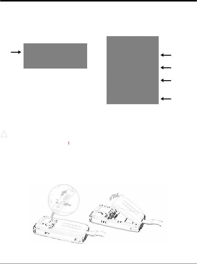
Battery Error Notification
If your terminal displays the following indicators, replace the main battery pack with a Honeywell battery pack. For information on how to remove the main battery pack from the terminal, see Replacing the Main Battery Pack on page 2-4.
•An “Authentication Error” pop up window appears during startup.
• appears in the Title bar at the top of the touch screen.
•The General Notification LED flashes red.
•A Notification appears on the Tile bar at the bottom of the touch screen.
Step 4. Boot the Terminal
The terminal begins booting as soon as power is applied. Do NOT press any keys or interrupt the boot process. When the boot process is complete, the Home screen appears, and the terminal is ready for use.
2 - 3
DRAFT COPY 11/11/11
Step 5. Set the Time Zone, Time, and Date
On the Home screen, tap the line that displays the time and date. When the Clock & Alarms screen appears, tap the arrow to the right of the time zone to open the drop down menu. Select the appropiate time zone from the menu. Set the correct time and date in the remaining fields and tap OK to save.
Replacing the Main Battery Pack
Note: Before replacing the main battery pack, read the Guidelines for Battery Pack Use and Disposal on page 3-13.
Ensure all components are dry prior to mating terminals/batteries with peripheral devices. Mating wet
!components may cause damage not covered by the warranty.
1.Press and hold the Power key  for approximately 5 seconds to put the terminal in Suspend Mode (see page 2-11).
2.Release the hand strap near the speaker on the back panel of the terminal.
3.Unlock the battery by sliding the latch away from the battery.
4.Wait at least 3 seconds, then slide the battery release button away from the stylus slot.
5.Remove the battery.
4 5
3
2 - 4
DRAFT COPY 11/11/11
6.Insert the new battery and apply gentle pressure to engage the latch.
Note: Make sure the stylus tether is not caught under the battery during installation.
7.Lock the battery by sliding the latch toward the battery pack.
Note: The terminal does not power ON unless the battery is locked.
8.Reattach the hand strap.
9.Press the Power key or the SCAN key to wake the terminal from Suspend Mode (see page 2-11).
We recommend use of Honeywell Li-ion battery packs. Use of any non-Honeywell battery may result in
!damage not covered by the warranty.
Home Screen
After the Dolphin terminal initializes the first time, you see the Home screen.
Tap  to reach the Start screen from the Home screen. Tap
 to access the Dolphin Wireless Manager (see page 8-4) from the home screen.
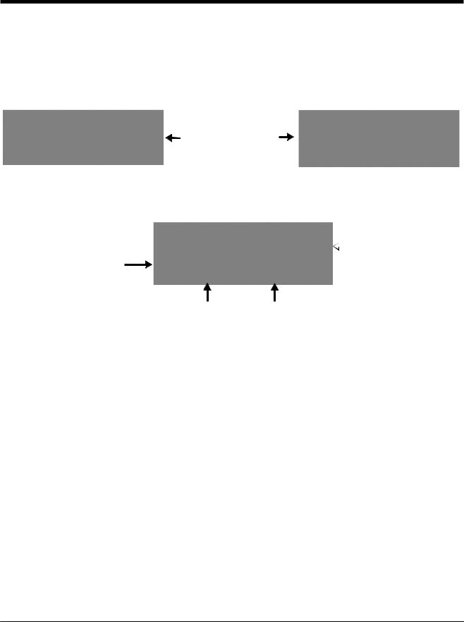
Title Bar
The Title bar, located at the top of the screen, displays the active program, the status of various system functions, and the current time. Tapping on the title bar provides access to the Horizontal Scroll. The scroll provides access to additional programs and application screens. For additional information, see Horizontal Scroll on page 2-8.
Text here indicates the active program.
Icons here indicate the status of various system functions.
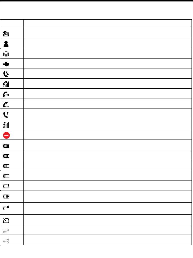
Icons in the Title Bar
Indicator Meaning
Synchronizing data
The terminal could not synchronize data with the workstation via ActiveSync.
New e-mail
New text message
2 - 5
DRAFT COPY 11/11/11
Icons in the Title Bar
Indicator Meaning
New voicemail
New instant message
Vibrate on
Ringer off
Speakerphone on
Voice call in progress
Calls are forwarded
Call on hold
Missed call
Data call in progress
A battery error has occurred. Replace the main battery pack with a Honeywell Li-ion battery pack.
Battery is has a full charge
Battery has a high charge
Battery has a medium charge
Battery has a low charge
Battery has a very low charge and requires charging
Terminal is running on external power. If a battery pack is installed, the battery is charging in the background.
The terminal is not connected to external power. A battery is installed, but is defective; specifically, its charge level cannot be measured.
No SIM card is installed
Active network connection
No active network connection
2 - 6

DRAFT COPY 11/11/11
Icons in the Title Bar
Indicator Meaning
GPRS available
GPRS connecting
GPRS in use
HSDPA available
HSDPA connecting
HSDPA in use
EDGE available
EDGE connecting
EDGE in use
UMTS available
UMTS connecting
UMTS in use
Radio is off
The radio is not connected to a network.
The radio is connected. The bars indicate the signal strength.
No radio signal
The terminal is searching for a signal.
Wi-Fi is on, but device is not connected
Wi-Fi data call
Pending alarm
Bluetooth
2 - 7
DRAFT COPY 11/11/11
Horizontal Scroll
The Horizontal Scroll, located at the top of most application windows, provides access to additional application screens. You can flick left or right on the scroll or tap each label on the scroll, until you get to the desired screen. Tapping a label to the left or right of the center item brings new labels into view.
Note: Tap the Title bar to access the horizontal scroll if it is not visible on the screen.
The content of the Horizontal scroll changes according to the open application.
Tile Bar
The Tile bar is located at the bottom of application windows.
The Tile bar displays icons you use to open and close screens, menues, and features.
 The Task tray displays icons for programs running in the background.
The icons change according to the open application.
Pop-Up Menus
With pop-up menus, you can quickly choose an action for a selected item. To access a pop-up menu, tap and hold the stylus on the item name of the action you want to perform. When the menu appears, lift the stylus, and tap the action you want to perform.
Tap anywhere outside the menu to close the menu without performing an action.
Selecting Programs
To see the programs loaded on your terminal, tap  to access the Start Menu. To open a
program, tap once on the program icon. To reposition an icon on the Start Menu, tap and hold the stylus on the icon, then drag the icon to the desired position.
2 - 8
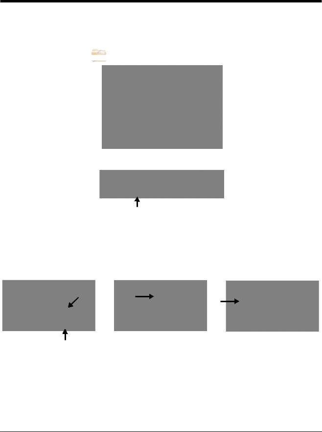
DRAFT COPY 11/11/11
File Explorer
You can also use the File Explorer to find files and organize these files into folders.
1. Tap  > File Explorer
  .
.
2.Tap the Up button at the bottom of the screen to move up one level in the directory.
3.You can move files in File Explorer by tapping and holding on the item you want to move, then tapping Cut or Copy on popup menu.
4.Navigate to the folder you want to move the file to, then tap and hold a blank area of the window.
5.Tap Paste on the pop-up menu.
Note: If there is no blank space available in the window, tap Menu on the command bar, navigate to the end of the menu using the down arrow, then tap Edit > Paste.
2 - 9

DRAFT COPY 11/11/11
File Provisioning on the 7800
\IPSM\Honeywell
The IPSM folder is the only partition on the 7800 that persists across a kernel upgrade (*.UPG file extension). During a kernel upgrade, files are automatically copied from the \IPSM\Honeywell\Autoinstall folder and then installed in the \Honeywell (root file system) folder as part of the upgrade process.
\IPSM\Honeywell\AutoInstall
The files in the IPSM\Honeywell\AutoInstall folder are only installed when a factory reset or kernel upgrade occurs. Once the files are installed, they persist through hard and soft resets. If a file is added to the folder and a hard or soft reset is performed, it will have no effect. If a program is manually removed using the Remove Programs application (see page 7-16), then the program is not automatically re-installed on a hard or soft reset.
\Honeywell
The Honeywell partition or root file system partition is persistent over a Hard Reset, Soft Reset, and the removal of the battery pack or the removal of AC power. However, during a kernel upgrade the root file system is reformatted so all data in the folder is deleted and replaced by any files in the \IPSM\Honeywell\AutoInstall folder as part of the upgrade process.
!To prevent data loss, back up all user data to an SD card or external memory device before performing an upgrade.
\Honeywell\AutoInstall
If you run a CAB file from within the \Honeywell\AutoInstall (user store) folder, after the program has been installed, the CAB file will be deleted from the User Store. The program remains installed through all successive Hard and Soft resets.
If you want the program to be part of the Autoinstall that occurs after a factory reset or software upgrade, paste the program file(s) in both the \IPSM\Honeywell\Autoinstallfolder and the
\Honeywell\Autoinstall.
Contact a Honeywell technical support representative for information on how to perform a factory reset or for information on available software upgrades for your Dolphin terminal. For contact information, see Customer Support on page 18-1. or go to www.honeywellaidc.com.
!To prevent data loss, back up all user data to an SD card or external memory device before performing an upgrade.
Search
The Search feature helps you quickly locate information. Tap  > Search Phone
  .
.
Enter the text you want to find, select a data type, and then tap Search. Select Larger than 64 KB in the Type drop-down field to quickly find information that is taking up storage space.
2 - 10

DRAFT COPY 11/11/11
Resetting the Terminal
There are three types of system resets: a soft reset, a hard reset, or a factory reset. The soft and hard resets preserve all data stored in the file system. Contact a Honeywell technical support representative for more information on how to perform a factory reset.
Soft Reset (Warm Boot)
A soft reset re-boots the device and preserves any objects created in RAM. You would perform a soft reset when: the terminal fails to respond, after installing some software applications, or after making changes to certain system settings, such as network cards.
1.Press and hold the BLUE  + END
+ END  keys for approximately 5 seconds.
2.The general notification LED flashes orange then green for approximately 3 seconds as the terminal resets.
3.When the reset is complete, the Home screen displays.
Hard Reset (Cold Boot)
A hard reset re-boots the device and closes any open applications running in RAM at the time of the reset.
1.Press and hold the BLUE  + SEND
  keys for approximately 5 seconds.
2.The general notification LED flashes orange then green for approximately 3 seconds as the terminal resets.
3.The terminal re-initializes.
Factory Reset
Contact a Honeywell technical support representative for information on how to perform a factory reset. For contact information, see Customer Support on page 18-1.
Suspend Mode
The terminal goes into Suspend Mode automatically when the terminal is inactive for a programmed period of time. You can program this time on the Advance tab of the Power System Setting; see Power on page 7-15.
To put the terminal into Suspend Mode manually, press and hold the POWER key  for approximately 5 seconds until the touch screen turns off.
To wake the terminal from Suspend Mode, press the POWER key  or SCAN key.
Note: You should always put the terminal in suspend mode before removing the battery. For information on removing the battery, see Replacing the Main Battery Pack on page 2-4.
2 - 11

DRAFT COPY 11/11/11
2 - 12

3 |
DRAFT COPY 11/11/11 |
|
Hardware Overview |
Standard Configurations for the 7800
WLAN & WPAN |
WLAN, WPAN & Camera |
||
• |
Microsoft Windows Embedded Handheld |
• Microsoft Windows Embedded Handheld |
|
|
6.5 Classic |
|
6.5 Classic |
• |
800MHz TI OMAP Processor |
• |
800MHz TI OMAP Processor |
• 256MB RAM X 512MB Flash |
• 256MB RAM X 512MB Flash |
||
• |
Six keyboard options |
• |
Six keyboard options |
• 3.7V Li-ion standard battery pack or |
• 3.7V Li-ion standard battery pack or |
||
|
extended rechargeable battery pack |
|
extended rechargeable battery pack |
• |
Adaptus Imaging Technology: N5603ER/ |
• |
Adaptus Imaging Technology: N5603ER/ |
|
SR/HD or N5600ER/SR/HD image engines |
|
SR/HD or N5600ER/SR/HD image engines |
• |
802.11a/b/g/n and Bluetooth |
• |
802.11a/b/g/n and Bluetooth |
|
|
• 3.0 megapixel auto control color camera |
|
WLAN, WPAN, with GPS |
WLAN, WPAN, with GPS & Camera |
||
• |
Microsoft Windows Embedded Handheld |
• Microsoft Windows Embedded Handheld |
|
|
6.5 Classic |
|
6.5 Classic |
• |
800MHz TI OMAP Processor |
• |
800MHz TI OMAP Processor |
• 256MB RAM X 512MB Flash |
• 256MB RAM X 512MB Flash |
||
• |
Six keyboard options |
• |
Six keyboard options |
• 3.7V Li-ion standard battery pack or |
• 3.7V Li-ion standard battery pack or |
||
|
extended rechargeable battery pack |
|
extended rechargeable battery pack |
• |
Adaptus Imaging Technology: N5603ER/ |
• |
Adaptus Imaging Technology: N5603ER/ |
|
SR/HD or N5600ER/SR/HD image engines |
|
SR/HD or N5600ER/SR/HD image engines |
• |
802.11a/b/g/n and Bluetooth |
• |
802.11a/b/g/n and Bluetooth |
• |
GPS |
• |
GPS |
|
|
• 3.0 megapixel auto control color camera |
|
WLAN, WPAN, & WWAN |
WLAN, WPAN, & WWAN with GPS |
||
• |
Microsoft Windows Embedded Handheld |
• Microsoft Windows Embedded Handheld |
|
|
6.5 Professional |
|
6.5 Professional |
• |
800MHz TI OMAP Processor |
• |
800MHz TI OMAP Processor |
• 256MB RAM X 512MB Flash |
• 256MB RAM X 512MB Flash |
||
• |
Six keyboard options |
• |
Six keyboard options |
• |
3.7V Li-ion extended rechargeable battery |
• 3.7V Li-ion extended rechargeable battery |
|
|
pack |
|
pack |
• |
Adaptus Imaging Technology: N5603ER/ |
• |
Adaptus Imaging Technology: N5603ER/ |
|
SR/HD or N5600ER/SR/HD image engines |
|
SR/HD or N5600ER/SR/HD image engines |
• 802.11a/b/g/n, Bluetooth, and GSM/ |
• 802.11a/b/g/n, Bluetooth, and GSM/ |
||
|
HSPA+ |
|
HSPA+ |
|
|
• |
GPS |
3 - 1

DRAFT COPY 11/11/11
WLAN, WPAN, WWAN with GPS & Camera |
WLAN, WPAN, & WWAN |
||
• Microsoft Windows Embedded Handheld |
• |
Microsoft Windows Embedded Handheld |
|
|
6.5 Professional |
|
6.5 Professional |
• |
800MHz TI OMAP Processor |
• |
800MHz TI OMAP Processor |
• 256MB RAM X 512MB Flash |
• 256MB RAM X 512MB Flash |
||
• |
Six keyboard options |
• |
Six keyboard options |
• |
3.7V Li-ion extended rechargeable battery |
• |
3.7V Li-ion extended rechargeable battery |
|
pack |
|
pack |
• |
Adaptus Imaging Technology: N5603ER/ |
• |
Adaptus Imaging Technology: N5603ER/ |
|
SR/HD or N5600ER/SR/HD image engines |
|
SR/HD or N5600ER/SR/HD image engines |
• |
802.11a/b/g/n, Bluetooth, and GSM/ |
• |
802.11a/b/g/n, Bluetooth, and GSM/CDMA |
|
HSPA+ |
|
|
•GPS
•3.0 megapixel auto control color camera
WLAN, WPAN, & WWAN with GPS |
WLAN, WPAN, WWAN with GPS & Camera |
•Microsoft Windows Embedded Handheld 6.5 Classic
•800MHz TI OMAP Processor
•256MB RAM X 512MB Flash
•Six keyboard options
•3.7V Li-ion extended rechargeable battery pack
•Adaptus Imaging Technology: N5603ER/ SR/HD or N5600ER/SR/HD image engines
•802.11a/b/g/n, Bluetooth, and GSM/CDMA
•GPS
•Microsoft Windows Embedded Handheld 6.5 Classic
•800MHz TI OMAP Processor
•256MB RAM X 512MB Flash
•Six keyboard options
•3.7V Li-ion extended rechargeable battery pack
•Adaptus Imaging Technology: N5603ER/ SR/HD or N5600ER/SR/HD image engines
•802.11a/b/g/n, Bluetooth, and GSM/ HSPA+ or GSM/CDMA
•GPS
•3.0 megapixel auto control color camera
Some configurations of the 7800 terminal are available with an external housing made of plastic that is specifically designed for the healthcare industry. For more information, see Healthcare Housing on page 3-11.
3 - 2
 Loading...