


 Loading...
301EM
MODULE D’EXPANSION
EXPANSION MODULE
Manuel d’utilisateur User Manual

Gas Detection Device
301EM
User Manual
ERP 512720 2/09

Notices and Trademarks
Copyright by Honeywell International Inc.
Release 512720 February 2009
While this information is presented in good faith and believed to be accurate, Honeywell disclaims the implied warranties of merchantability for a particular purpose and makes no express warranties except as may be stated in its written agreement with and for its customers.
In no event is Honeywell liable to anyone for any indirect, special or consequential damages. The information and specifications in this document are subject to change without notice.
Honeywell Analytics
4005 Matte Blvd, Unit G
Brossard, Quebec, Canada, J4Y 2P4
301EM User Manual |
iii |

Symbol Definitions
The following table lists the symbols used in this document to denote certain conditions:
Symbol |
Definition |
ATTENTION: Identifies information that requires special consideration
TIP: Identifies advice or hints for the user, often in terms of performing a task
REFERENCE _ INTERNAL: Identifies an additional source of information within the bookset.
Indicates a situation which, if not avoided, may
CAUTION result in equipment or work (data) on the system being damaged or lost, or may result in the
inability to properly operate the process.
CAUTION: Indicates a potentially hazardous situation which, if not avoided, may result in minor or moderate injury. It may also be used to alert against unsafe practices.
CAUTION: Symbol on the equipment refers the user to the product manual for additional information. The symbol appears next to required information in the manual.
WARNING: Indicates a potentially hazardous situation which, if not avoided, could result in serious injury or death.
WARNING symbol on the equipment refers the user to the product manual for additional information. The symbol appears next to required information in the manual.
301EM User Manual |
v |

Contents |
|
INTRODUCTION .............................................................. |
9 |
Description ............................................................................................... |
9 |
Intended Use ............................................................................................ |
9 |
Unpacking ................................................................................................ |
9 |
INSTALLATION INSTRUCTIONS ................................. |
10 |
Installation Guidelines ....................................................................... |
10 |
Wall Mount Installation ...................................................................... |
10 |
Recommended Sensor Installation Heights ........................................... |
11 |
Determining the Number of Transmitters .......................................... |
12 |
Range and Alarm Levels ........................................................................ |
13 |
Installing Optional Remote Sensors ....................................................... |
14 |
WIRING DETAILS .......................................................... |
16 |
System Wiring ................................................................................... |
16 |
Power Connections ................................................................................ |
17 |
Connecting sensors to transmitter ......................................................... |
18 |
Communication to Controller ................................................................. |
19 |
Relay Outputs ........................................................................................ |
19 |
24 Vdc Output ........................................................................................ |
20 |
4-20 mA Configuration ........................................................................... |
20 |
4-20 Output Configuration ...................................................................... |
22 |
CALIBRATION / PROGRAMMING ................................ |
27 |
User Interface .................................................................................... |
27 |
Operating Mode ..................................................................................... |
27 |
Pushbutton Definitions ........................................................................... |
28 |
Programming the Unit ........................................................................ |
29 |
Accessing the Programming Menus .................................................. |
30 |
Setting the Unit’s Address ................................................................. |
31 |
Configuring a Sensor ......................................................................... |
32 |
Changer the Sensor Address ................................................................. |
32 |
Adding a new Sensor ............................................................................. |
33 |
Removing a Sensor ............................................................................... |
34 |
301EM User Manual |
vii |

Adding Remote Panels ...................................................................... |
34 |
Using the Service Menu .................................................................... |
35 |
Using the SetEvent Menu .................................................................. |
36 |
Changing Event Configurations ............................................................. |
37 |
Using the SetRelay Menu .................................................................. |
40 |
Deactivating the Buzzer ..................................................................... |
41 |
Configuring the Unit’s Alarms ............................................................ |
42 |
Setting the Unit’s Analog Outputs ...................................................... |
43 |
Calibrating the Unit ............................................................................ |
44 |
Connecting the Hardware ...................................................................... |
44 |
Adjusting the Zero (If Required) ............................................................. |
45 |
Calibrating the Sensor ........................................................................... |
46 |
301EM Specifications ...................................................................... |
48 |
301IRFS Specifications ..................................................................... |
49 |
Maintenance ...................................................................................... |
51 |
Replacement Parts ................................................................................ |
51 |
Cleaning ................................................................................................. |
51 |
APPENDIX A .................................................................. |
52 |
Available Pre-programmed configurations ........................................ |
52 |
Type 1 CND (B-52 Canadian Standard for R123) ................................. |
52 |
Type 2 CND (B-52 Canadian Standard for other Refrigerants) ............. |
52 |
Type 3 US (ASHRAE 15 Standard for Refrigerants) ............................. |
53 |
Type 4 (Default configuration - other than B-52 and ASHRAE 15) ........ |
54 |
LIMITED WARRANTY ................................................... |
55 |
Limited Warranty .................................................................................... |
55 |
Re-Stocking Policy ................................................................................. |
55 |
Exclusions .............................................................................................. |
56 |
Warranty Limitation and Exclusion ......................................................... |
56 |
Disclaimer of Unstated Warranties ........................................................ |
57 |
Limitation of Liability ............................................................................... |
57 |
viii |
301EM User Manual |
Introduction
Introduction
Description
Honeywell introduces a breakthrough innovation in refrigerant, toxic and combustible gas monitoring as part of our continued commitment to cutting-edge technology and customer satisfaction.
The result of extensive research and design, the 301EM uses the latest in infrared technology. The 301EM can have up to 20 sensors connected to allow for accurate monitoring of even the lowest gas concentration.
The 301EM (with an LCD display and keypad) can be installed in a location separate from the detection area, making it safer to monitor gas readings.
The 301EM also offers 4-20mA outputs, relay outputs, Modbus communication, audible alarm options and is compatible with our 301C controller.
Intended Use
The availability and costs associated with refrigerant gases make monitoring a necessity for managing equipment rooms. A Honeywell refrigerant detector provides early warning of refrigerant leaks, which enhancing the refrigerant conservation strategy by monitoring equipement room refrigerant gas concentrations. Toxic and combustible sensors can be linked to the 301EM, allowing it to meet the broadest range of customer requirements. The 301EM Expansion Module has been carefully designed with several factory programmed configurations that meet or exceed ASHRAE B-52 or 15-2201 standards.
Unpacking
After opening the package, remove the equipment and components. Please make sure that all the items described on the order form or bill of lading are actually in the box and are undamaged.
301EM User Manual |
9 |
Installation Instructions
Installation Guidelines
Installation Instructions
Installation Guidelines
These guidelines must be strictly observed to ensure that the equipment will work properly. If they are not applied, Honeywell will not recognize any liability in case of improper operation:
Make sure to locate all units easily accessible for proper service.
•Avoid any location where units could be subject to vibrations.
•Avoid any location close to any electromagnetic interference.
•Avoid any location where there are large temperature swings.
•Verify local requirements and existing regulations which may affect the choice of location.
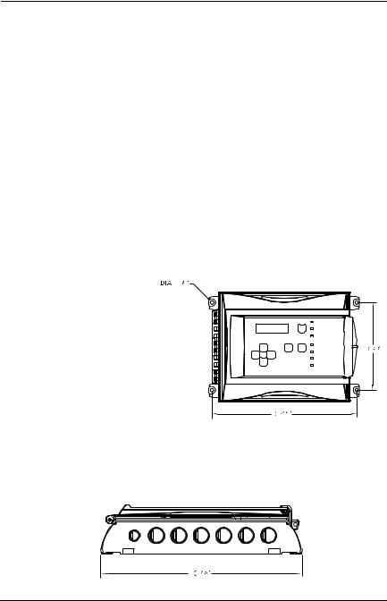
Wall Mount Installation
We recommend installing the monitor at a height of 1.5 m (4.9 ft) from the ground (eye level).
• Mark two holes 162mm (6 3/8”) apart in height
• Mark two holes268.3mm (10 9/16”) apart in width
• Drill 6.35mm (1/4”) holes and prepare as necessary
• Mount unit with appropriate screws
Remember to pass all wiring through knock-outs at base of unit, using the appropriate conduit.
10 |
301EM User Manual |

Installation Instructions
Wall Mount Installation
Recommended Sensor Installation Heights
The installation heights recommended represent general guidelines. Always confirm with local laws and regulations before proceeding, as these take precedence over manufacturer's recommendations.
|
Detected Gas |
Relative Density |
Installation Height |
|
(air = 1) |
||
|
|
|
|
|
|
|
|
CO |
Carbon Monoxide |
0.968 |
1 - 1.5 m (3 - 5 ft.) from floor |
*NO2 |
Nitrogen Dioxide |
1.58 (cold) |
30 cm -1 m (1-3 ft.) from ceiling |
H2 |
Hydrogen |
0.07 |
30 cm (1 ft.) from ceiling |
CL2 |
Chlorine |
2.50 |
30 cm (1 ft.) from floor |
H2S |
Hydrogen Sulfide |
1.19 |
30 cm (1 ft.) from floor |
O2 |
Oxygen |
1.43 |
1 - 1.5 m (3 - 5 ft.) from floor |
HCL |
Hydrogen Chloride |
1.30 |
30 cm (1 ft.) from floor |
HCN |
Hydrogen Cyanide |
0.932 |
30 cm (1 ft.) from ceiling |
ETO |
Ethylene Oxide |
1.50 |
30 cm (1 ft.) from floor |
SO2 |
Sulfur Dioxide |
2.25 |
30 cm (1 ft.) from floor |
R11 |
Refrigerants |
5.04 |
30 cm (1 ft.) from floor |
R12 |
Refrigerants |
4.20 |
30 cm (1 ft.) from floor |
R13B1 |
Refrigerants |
5.14 |
30 cm (1 ft.) from floor |
R114 |
Refrigerants |
5.9 |
30 cm (1 ft.) from floor |
R22 |
Refrigerants |
3.11 |
30 cm (1 ft.) from floor |
R123 |
Refrigerants |
5.27 |
30 cm (1 ft.) from floor |
R125 |
Refrigerants |
4.14 |
30 cm (1 ft.) from floor |
R134A |
Refrigerants |
3.52 |
30 cm (1 ft.) from floor |
R227 |
Refrigerants |
5.90 |
30 cm (1 ft.) from floor |
R245A |
Refrigerants |
|
30 cm (1 ft.) from floor |
R404A |
Refrigerants |
3.43 |
30 cm (1 ft.) from floor |
R407C |
Refrigerants |
3.0 |
30 cm (1 ft.) from floor |
R410A |
Refrigerants |
3.0 |
30 cm (1 ft.) from floor |
R507 |
Refrigerants |
3.43 |
30 cm (1 ft.) from floor |
R508b |
Refrigerants |
|
30 cm (1 ft.) from floor |
COMB |
Most combustibles are heavier than air, with the exception of methane, |
||
|
hydrogen,ethylene and acetylene. Sensors for gases that are heavier than |
||
|
air should be installed approximately 30 cm (1 foot) from the floor. For |
||
|
combustibles that are lighter than air, sensors should be installed 30 cm (1 |
||
|
foot) from the ceiling, close to the potential leak source. |
||
|
|
|
|
* May differ in certain applications. Hot NO2 from exhaust systems is lighter than ambient air.
301EM User Manual |
11 |

Installation Instructions
Determining the Number of Transmitters
Determining the Number of Transmitters
The number of units required to protect an area is determined by the unit’s detection radius, which depends on the type of gas detected, as shown in the following table.
|
Gas Detected |
Surveillance |
Area Covered |
|
Radius |
||
|
|
|
|
|
|
|
|
CO |
Carbon monoxide |
15 m (50 ft) |
707 m2 (7610 ft2) |
NO2 |
Nitrogen dioxide |
15 m (50 ft) |
707 m2 (7610 ft2) |
|
Others |
7 m (23 ft) |
154 m2 (1658 ft2) |
|
|
|
|
12 |
301EM User Manual |

Installation Instructions
Determining the Number of Transmitters
Range and Alarm Levels
|
Gas Detected |
Range |
Alarm A |
Alarm B |
Alarm C |
|
|
|
|
|
|
CL2 |
Chlorine |
0-15 ppm |
0.5 ppm |
1 ppm |
13,5 ppm |
CO |
Carbon monoxide |
0-250 ppm |
25 ppm |
200 ppm |
225 ppm |
H2S |
Hydrogen sulfide |
0-50 ppm |
10 ppm |
15 ppm |
45 ppm |
NO2 |
Nitrogen dioxide |
0-10 ppm |
0.72 ppm |
2 ppm |
9 ppm |
O2 |
Oxygen |
0-25% Vol. 19.5% Vol. |
22% Vol. |
22,5% Vol. |
|
SO2 |
Sulfur dioxide |
0-10 ppm |
2 ppm |
5 ppm |
9 ppm |
R-123 |
Refrigerant |
0-1000 ppm |
50 ppm |
500 ppm |
900 ppm |
R-11 |
Refrigerant |
0-1000 ppm |
250 ppm |
500 ppm |
900 ppm |
R-12 |
Refrigerant |
0-1000 ppm |
250 ppm |
500 ppm |
900 ppm |
R13B1 |
Refrigerant |
0-1000 ppm |
250 ppm |
500 ppm |
900 ppm |
R114 |
Refrigerant |
0-1000 ppm |
250 ppm |
500 ppm |
900 ppm |
R-22 |
Refrigerant |
0-1000 ppm |
250 ppm |
500 ppm |
900 ppm |
R-125 |
Refrigerant |
0-1000 ppm |
250 ppm |
500 ppm |
900 ppm |
R134A |
Refrigerant |
0-1000 ppm |
250 ppm |
500 ppm |
900 ppm |
R227 |
Refrigerant |
0-1000 ppm |
250 ppm |
500 ppm |
900 ppm |
R245A |
Refrigerant |
0-1000 ppm |
250 ppm |
500 ppm |
900 ppm |
R404A |
Refrigerant |
0-1000 ppm |
250 ppm |
500 ppm |
900 ppm |
R407C |
Refrigerant |
0-1000 ppm |
250 ppm |
500 ppm |
900 ppm |
R410A |
Refrigerant |
0-1000 ppm |
250 ppm |
500 ppm |
900 ppm |
R507 |
Refrigerant |
0-1000 ppm |
250 ppm |
500 ppm |
900 ppm |
R508b |
Refrigerant |
0-1000 ppm |
250 ppm |
500 ppm |
900 ppm |
Comb |
Combustibles |
0-100% LEL |
25% LEL |
50% LEL |
90% LEL |
|
|
|
|
|
|
A different alarm level may have been programmed in order to satisfy the constraints of a particular application.
Deadband and Accuracy
(Refrigerant detection)
The deadband is the area of signal or detection range where no action occurs. The IRF deadband is 20 ppm.
301EM User Manual |
13 |
Installation Instructions
Determining the Number of Transmitters
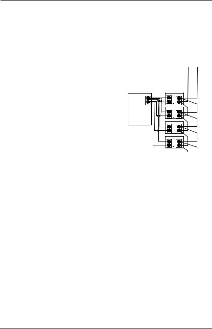
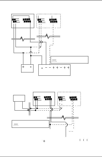
Installing Optional Remote Sensors
301IRFS Sensor
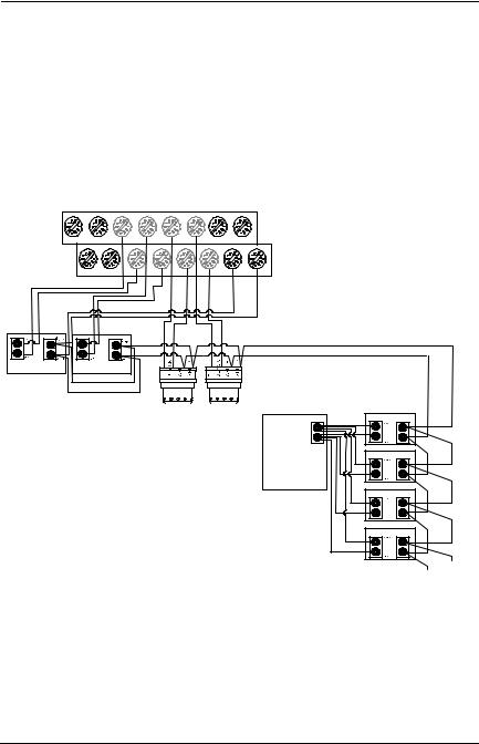
The refrigerant sensor should be installed at the recommended height, which is 30 cm (1 foot) from the floor.
Communication cables should be 2-24 AWG, twisted and shielded (Belden 9841 or equivalent), which should be connected in a daisy chain from the 301EM (as shown).
Power cables should be 14 AWG cable, maximum length of 60 m (200 ft). The first four sensor power cables may be wired directly to the 301EM. Additional sensors require an external power supply (one per group of four sensors, to a maximum of 20 sensors in total), using the same rated cable as units wired to the 301EM.
|
|
From |
|
|
|
301EM |
|
|
|
A |
|
|
|
(white) |
B |
|
|
|
|
|
Power |
Comm. |
(green) |
|
|
||
External V- (black) |
sensor #5 |
|
|
Power |
|
|
|
Supply |
|
|
|
V+ (red) |
sensor #6 |
|
|
HPTV5DC8, |
|
||
|
|
|
|
Input: 115 VAC 1A, |
|
|
|
Output: 4.0A@6 and |
|
|
|
12VDC, 2.5A@ |
|
|
|
24VDC |
sensor #7 |
|
|
|
|
||
sensor #8
To next sensors
14 |
301EM User Manual |
Installation Instructions
Determining the Number of Transmitters
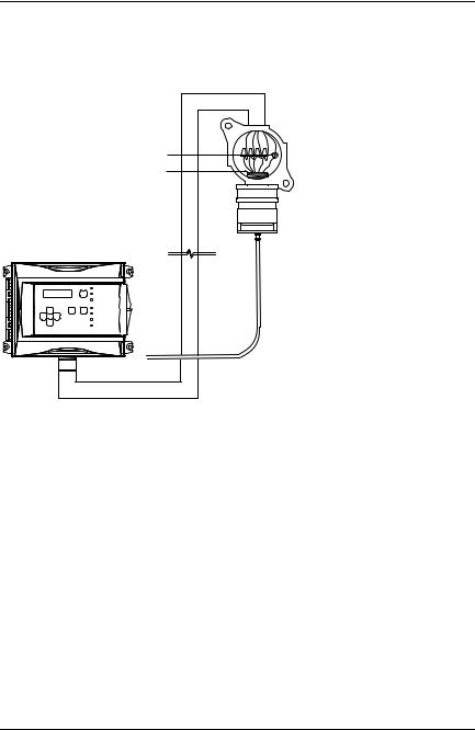
S301D2 Remote Sensor
The drawing below illustrates the connection for a 301D2 sensor with the D2RS-PC option.
Shielding must be grounded at the terminal
Thread dimension 3/4
Monitor |
This housing not included |
Calibration tubing
Communication: Use 2- 24 AWG, twisted and shielded cable (Belden 9841 or equivalent)
Power: Use 2-18 AWG cable, maximum length of 160 m (500 ft).
301EM User Manual |
15 |

WIRING DETAILS
System Wiring
WIRING DETAILS
System Wiring
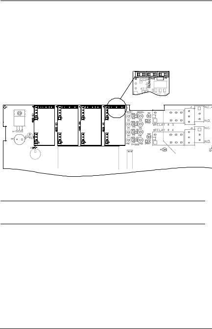
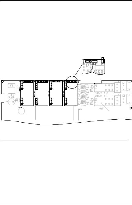
Both GasPoint II (301D2) and IRFS sensors can be linked to the 301EM system. The drawing below illustrates an overview of PCB terminal wiring.
.
EOL Positions
Disabled R
J1 |
N.C. |
|
|
|
N.O. |
J6  N.C.
N.C.
N.O.
SILENCE
SW1
LCD screen
RC
UP
SW2
ESC |
|
ENTER |
SW6 |
|
SW7 |
SW3 |
SW4 |
FAN |
RESET |
|
|
|
|
|
|
DOWN |
|
|
|
|
|
|
|
|
|
SW8 |
|
|
|
|
|
|
+VDC RED |
|
|
|
|
J8 |
|
24 |
IN |
|
|
|
|
|
J1 |
|
|
V+ |
V- |
|
|
|
|
J10 |
|
|
|
|
|
|
|
|
|
6 |
|
|
|
|
|
|
|
|
|
|
|
|
|
|
|
|
|
|
|
|
B + - + |
- |
#1 |
|
|
|
|
A |
B J17 |
SHIELD A B A |
OUT |
||
|
24 |
IN |
|
|
|
|
Contact |
|
|
|
V+ |
V- |
GND |
BLACK WHITE |
GREEN |
|
input |
|
|
|
|
|
|
|
|
Terminal J10 |
Terminal J16 |
|
|
|
|
|
|
|
|
Used for communication |
Used (normally) to |
|
|
|
|
|
|
|
|
connections to a control |
connect a breakglass |
||
|
|
|
|
|
|
unit (such as 301C) |
switch (see page 23) |
||
J9


 + 4@20
|
- 4@20 |
OUT #2 OUT #3 |
4@20 (4) 4@20 (3) 4@20 (2) 4@20 (1) |
Terminals J8, J9
see pages 22, 25 and 27 for complete 4-20 wiring details
J13 J14
N.O. N.C. N.O. N.C.
Terminals J13, J14, J1, J6
See page 21 for complete relay wiring instructions
V+ |
V- |
A |
B |
Sensor #1 IRF
Sensor #2 GasPoint2
Terminal J17
see page 20 for complete sensor wiring details
16 |
301EM User Manual |
WIRING DETAILS
System Wiring
Power Connections
The power requirement range is 22-27 Vac, 29-38 Vdc, 2.0 A max. The polarity is not important. The system must be grounded on the transformer.
24 IN
V+ V-
+VDC RED
A dedicated circuit-breaker must be used.
Separate power supplies must be provided for each group of 4 sensors
24 |
IN |
The 301EM requires a 100VA transformer that must be installed near the unit to prevent voltage loss. If there is no
CAUTION transformer, or if the transformer capacity is insufficient, 24 Vdc outputs will not have sufficient power, which will have an impact on RFS/RFSA and other device options.
301EM User Manual |
17 |
WIRING DETAILS
System Wiring
Connecting sensors to transmitter
Connect the sensor to the transmitter as shown in the diagram below. The maximum distance between sensor and power supply is 200 ft. (60 m) for refrigerant and 500 ft. (160 m) for toxic and combustible gases. Color coding (black, red, green, white) must be respected.
The first four sensors can be connected directly to the 301EM. Additional sensors must have external power supplies (T300VA, 120/24Vac-300VA Transformer) for every group of 4 sensors and communication must be in daisy-chain connection
+VDC RED
|
S |
S |
S |
S |
||
|
e |
e |
|
e |
e |
|
|
n |
n |
n |
n |
||
|
s |
s |
s |
s |
||
|
o |
o |
o |
o |
||
|
r |
|
r |
|
r |
r |
|
# |
# |
|
# |
# |
|
|
1 |
2 |
3 |
4 |
||
24 |
IN |
GND |
|
|
|
A B J17 |
|
BLACK |
WHITE GREEN |
||||
V+ |
V- |
|
|
|
|
|
|
A |
sensor #1 |
sensor #2 |
POWER: Maximum 4 power
connections direct to unit. Additional power sources required for every group of 4 sensors.
COMMUNICATION: Communication must be connected in daisy chain configuration.
sensor #3 |
sensor #4 |
A |
B |
|
(white) |
||
(green) |
||
Power Comm. |
||
|
External V- (black) |
sensor #5 |
|
Power |
|
|
Supply |
|
|
V+ (red) |
sensor #6 |
|
HPTV5DC8, |
||
|
||
Input: 115 VAC 1A, |
|
|
Output: 4.0A@6 and |
|
|
12VDC, 2.5A@ 24VDC |
sensor #7 |
|
|
||
|
sensor #8 |
To next sensors
Note: Use 2-18 AWG wire gauge for toxic and explosives sensor power wiring. Use 14 AWG wire gauge for refrigerant sensor power wiring.
18 |
301EM User Manual |
WIRING DETAILS
System Wiring
Communication to Controller
Terminal J10 is for communication connections from the 301EM to the 301C Controller. The cables must be grounded using the shield terminal. The network can be up to 2000 ft. (609 m) per channel. The length of a T- tap can be a maximum of 65 feet (20 m). A maximum of 130 ft. (40 m) for all the T-taps must be respected.This diagram illustrates network communication wiring on terminal J10; wires come in from a previous device and go out to the next device.
J10 |
J16 |
SHIELD A |
B |
A |
B |
Contact |
|
input |
|||||
|
|
|
|
||
Previous |
|
|
|
Next |
|
|
|
|
|
COMMUNICATION
Communication Wire Gauge: 2-24 AWG (Belden 9841) Twisted and shielded cable 2000 feet (600 m) per channel T-tap: 65 feet (20 m) / T-tap
130 feet (40 m) total
Relay Outputs
The relay outputs will withstand up to 5 amps at 30 Vdc or 250 Vac (resistive load only). They can be used to activate horns, strobes, etc. Refer to the drawing for proper wiring.
Failsafe Relay Outputs
When power is applied to the 301EM, these relays are also powered up. The devices connected to these outputs will be triggered when power is cut, which allows detection of power failures or interruptions.
The 301EM is factory configured in Normal mode, which means that the relay outputs are not in failsafe mode.
|
|
|
|
|
|
|
N.C. |
|
|
|
|
|
|
|
N.O. |
|
|
|
|
|
|
|
N.C. |
|
|
|
|
|
|
|
N.O. |
RELAY OUTPUTS |
|
|
|
|
|||
6 |
4 |
2 |
Normally |
3+5 |
|
|
|
|
|
|
|
|
|
||
|
|
|
open |
4+6 |
|
|
|
|
|
|
Normally |
1+3 |
|
|
|
5 |
3 |
1 |
closed |
2+4 |
|
|
|
|
|
|
|
N.O. |
N.C. |
N.O. |
N.C. |
See the APPENDIX section for more details about B-52 and ASHRAE 15 standard configurations.
301EM User Manual |
19 |
WIRING DETAILS
System Wiring
24 Vdc Output
The three 24 Vdc / 250 mA outputs are provided to activate DC horn, strobe, etc.
J8 |
J9 |
Contact
input
Note: Terminal connectors labeled OUT #1 and OUT #2 must be dedicated to RFSA use only, if applicable.
Terminal connector labeled OUT #3 must be used for RFS only, if applicable.
RFS: Optional built-in stobe
RFSA: Optional built-in stobe and horn
4-20 mA Configuration
Output 4-20 mA, J9
The 4-20 mA output option will provide a real time analog readout of the gas concentration read by the 301EM for each of its sensors. It can be connected to a third party controller, DDC, BMS, etc.
Polarity must be observed.
CAUTION
Do not apply electrical power to the 301EM until all connections are made. Significant damage can result from incorrect wiring.
20 |
301EM User Manual |

WIRING DETAILS
System Wiring
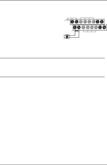
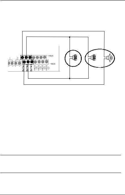
Contact Input, J16
The contact input is mainly used to connect a manual break glass switch to comply with the mechanical code. It is also possible to connect a third break glass switch in series if needed.
The drawing illustrates the ASHRAE 15 configuration where:
Contact 1 = Electrical shut down (ASHRAE 15 config.)
Contact 2 = Fan activation (ASHRAE 15 config.)
J16
|
|
|
|
|
|
|
|
|
|
|
|
|
|
|
|
|
|
|
|
|
|
|
|
|
|
|
|
|
|
|
|
|
|
|
|
|
|
|
|
|
|
|
|
|
|
|
|
|
|
|
|
|
|
|
|
|
|
|
|
|
|
|
|
|
|
|
|
|
|
|
|
|
|
|
Contact 1 |
Contact 2 |
|||||||||||||
301EM User Manual |
21 |
WIRING DETAILS
System Wiring
4-20 Output Configuration
4-20 mA Current Sourcing Output Configuration
The transmitter supplies the loop current. The maximum impedance supported by the loop is 400 ohms. Set jumpers on JP4 at 1-2, 3-4 and 5- 6.
A dedicated power supply must be used with each 301EM. CAUTION Considerable damage may occur if this condition is not strictly
followed.
22 |
301EM User Manual |

WIRING DETAILS
System Wiring
Current Sourcing Output Configuration
TRANSMITTER 1 |
TRANSMITTER X |
24 VAC
24 VAC |
|
4-20 mA |
|||
J16 |
J9 |
|
|
|
|
|
|
|
|
+4@20 |
|
|
|
|
|
-4@20 |
|
V+ V- |
#4 |
#3 |
#2 |
#1 |
|
Sensor |
Sensor |
Sensor |
Sensor |
||
|
|||||
 24 VAC
J16
V+ V-
4-20 mA
J9
+4@20 |
-4@20 |
Sensor #4 |
|
Sensor #3 |
|
Sensor #2 |
Sensor #1 |
|
|||||
|
|
||||
|
|
24 VAC
LEGEND
-ONE TRANSMITTER CONNECTED
-MORE THAN ONE TRANSMITTER CONNECTED
DDC SYSTEM
301EM User Manual |
23 |
WIRING DETAILS
System Wiring
Output Loop-Powered Operation
(Factory Setting)
The 4-20 mA output is factory set for loop-powered operation and requires a power source of 12 Vdc to 30 Vdc. The overall impedance depends on the voltage supplied at the 4-20 mA loop. Set jumpers on JP4 at 2-3, 4-5 and 6 for this type of configuration.
Permitted Impedance in the 4-20 mA Loop
Voltage Source Applied |
Total Impedance |
12 Vdc |
400 Ohms |
16 Vdc |
600 Ohms |
20 Vdc |
800 Ohms |
24 Vdc |
1,000 Ohms |
30 Vdc |
1,300 Ohms |
|
|
24 |
301EM User Manual |
WIRING DETAILS
System Wiring
3 Wire Configuration
TRANSMITTER 1
24 VAC |
|
4-20 mA |
||
J16 |
J9 |
|
|
|
|
|
|
|
+4@20 |
|
|
|
|
-4@20 |
V+ V- |
#4 |
#3 |
#2 |
#1 |
|
Sensor |
Sensor |
Sensor |
Sensor |
TRANSMITTER X
|
24 VAC |
4-20 mA |
|
|
|
|
|
J16 |
J9 |
||
|
|
|
|
+4@20 |
|
|
|
|
-4@20 |
V+ V- |
#4 |
#3 |
#2 |
#1 |
|
Sensor |
Sensor |
Sensor |
Sensor |
LEGEND
ONE TRANSMITTER CONNECTED
MORE THAN ONE TRANSMITTER CONNECTED
24 VDC |
DDC SYSTEM |
|
4 Wire Configuration
TRANSMITTER 1 |
|
|||
24 VAC |
|
4-20 mA |
||
J16 |
J9 |
|
|
|
24 VAC |
|
|
|
+4@20 |
|
|
|
-4@20 |
|
V+ V- |
#4 |
#3 |
#2 |
#1 |
|
Sensor |
Sensor |
Sensor |
Sensor |
TRANSMITTER X |
|
|
||
24 VAC |
4-20 mA |
|||
J16 |
J9 |
|
|
|
|
|
|
|
+4@20 |
|
|
|
|
-4@20 |
V+ V- |
#4 |
#3 |
#2 |
#1 |
|
Sensor |
Sensor |
Sensor |
Sensor |
LEGEND
- ONE TRANSMITTER CONNECTED
- MORE THAN ONE TRANSMITTER CONNECTED
|
|
|
|
|
|
|
|
|
|
|
|
|
|
|
|
|
|
|
|
|
|
|
|
|
|
|
|
|
|
|
|
|
|
|
|
|
|
|
|
|
|
|
|
|
|
|
|
|
|
|
|
|
|
|
|
|
|
|
|
|
|
|
|
|
|
|
|
|
|
|
|
|
|
DDC SYSTEM |
||
|
|
|
|
|
|
|
|
|||
|
|
|
|
|
|
|
|
|||
24 VDC |
|
|
|
|||||||
|
|
|
|
|
|
|
|
|
|
|
301EM User Manual |
25 |

Programming and Calibration
User Interface
Programming and Calibration
User Interface
When power is initially applied, the unit’s LCD screen will display the product’s name and firmware version.
Operating Mode
Normal Mode |
When the 301EM is in Normal mode, no user |
|
intervention is required. The display will scroll to |
|
display (gas and concentration) readings from up to 20 |
|
sensors. The Tx LED will blink when there is a |
|
transmission on the communication channel (if the unit |
|
is connected to a controller) |
Alarm Mode |
Red LEDs light according to the alarm level detected |
|
(Alarm A, B or C). If the unit is equipped with a horn or |
|
strobe, these will also be activated with the |
|
corresponding alarm. |
Fault Mode |
If a sensor has communication problems, the yellow |
|
Fault LED lights. This LED will also light when the |
|
service alarm is activated. |
Programming |
The programming mode is password protected. |
Mode |
Only qualified technicians should access this mode. |
|
The enter key provides access to programming and |
|
confirms an entry, while the arrow keys allow |
|
technicians to increase or decrease values and scroll |
|
throughout the menus. |
301EM User Manual |
27 |
Programming and Calibration
User Interface
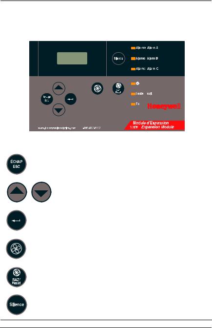
Pushbutton Definitions
The 301EM has “pushbuttons” that serve as an interface to the unit’s programming functions. Below is a description for each button’s function:
|
|
|
|
|
|
|
|
|
|
|
|
|
|
|
|
|
|
|
|
|
|
|
|
|
|
|
|
|
|
|
|
|
|
|
|
|
|
|
|
|
|
|
|
|
|
|
|
Key |
Description |
||||||||||
|
|
|
|
|
|
|
|
|
|
|
|
|
|
|
Used to exit the menus or cancel an input. Also used to |
||||||||
|
|
|
stop the alternating reading between the connected |
||||||||
|
|
|
sensors. |
||||||||
|
|
|
|
|
|
|
|
|
|
|
|
|
|
|
Used to scroll through the sensor data displays or through |
||||||||
|
|
|
menus or to change a specific value. |
||||||||
|
|
|
|
|
|
|
|
|
|
|
|
|
|
|
Serves as an “enter” key and is used to access a |
||||||||
|
|
|
programming field or to confirm a specific value. |
||||||||
|
|
|
|
|
|
|
|
|
|
|
|
|
|
|
Fan start switch (For B-52 or ASHRAE 15 programming). |
||||||||
|
|
|
See the Events table |
||||||||
|
|
|
|
|
|
|
|
|
|
|
|
|
|
|
Used to reset all outputs after system returns to normal |
||||||||
|
|
|
operating mode (linked to the Reset function in the Events |
||||||||
|
|
|
|||||||||
|
|
|
menu). |
||||||||
|
|
|
|
|
|
|
|
|
|
|
|
|
|
|
Turns off the buzzer and horns |
||||||||
28 |
301EM User Manual |
Loading...