


 Loading...
Genesis 7580
Presentation Area Imager
User’s Guide

Disclaimer
Honeywell International Inc. (“HII”) reserves the right to make changes in specifications and other information contained in this document without prior notice, and the reader should in all cases consult HII to determine whether any such changes have been made. The information in this publication does not represent a commitment on the part of HII.
HII shall not be liable for technical or editorial errors or omissions contained herein: nor for incidental or consequential damages resulting from the furnishing, performance, or use of this manual.
This document contains propriety information that is protected by copyright. All rights reserved. No part of this document may be photocopied, reproduced, or translated into another language without the prior written consent of HII.
© 2010 - 2012 Honeywell International Inc. All rights reserved.
Web Address: www.honeywellaidc.com
Trademarks
SwiftDecoder, MetroSelect, and MetroSet are trademarks or registered trademarks of Metrologic Instruments, Inc. in the United States and/or other countries.
Microsoft, Windows 95, and Windows are registered trademarks of Microsoft Corporation.
IBM is a trademark of International Business Machines Corporation.
Checkpoint is a registered trademark of Checkpoint Systems, Inc.
Other product names mentioned in this manual may be trademarks or registered trademarks of their respective companies and are the property of their respective owners.
Patents
For patent information, please refer to www.honeywellaidc.com/patents.

Table of Contents |
|
Introduction |
|
Product Overview ............................................................................................. |
1 |
Base Kit Components....................................................................................... |
2 |
Optional Accessories........................................................................................ |
2 |
MS7580 Components....................................................................................... |
4 |
Labels............................................................................................................... |
5 |
Maintenance..................................................................................................... |
5 |
Cable Installation and Removal........................................................................ |
6 |
Interface Installation |
|
RS232 .............................................................................................................. |
7 |
Keyboard Wedge.............................................................................................. |
8 |
RS485 .............................................................................................................. |
9 |
USB................................................................................................................ |
10 |
Mounting the MS7580 |
|
Components of Adapter Kit 46-00911 ............................................................ |
13 |
Components of Wall Mount Kit 46-00913....................................................... |
13 |
Installation of Adapter Kit 46-00911 ............................................................... |
14 |
Installation of Wall Mount Kit 46-00913 .......................................................... |
16 |
Operation |
|
Modes of Operation........................................................................................ |
17 |
Audible Indicators........................................................................................... |
19 |
Visual Indicators ............................................................................................. |
20 |
Failure Modes................................................................................................. |
21 |
Field of View................................................................................................... |
22 |
Depth of Field by Minimum Bar Code Element Width .................................... |
23 |
IR Activation Range........................................................................................ |
24 |
Illumination Source......................................................................................... |
25 |
IR Source ....................................................................................................... |
26 |
Targeting Source............................................................................................ |
27 |
|
iii |

Troubleshooting Guide......................................................................... |
29 |
Design Specifications........................................................................... |
33 |
Applications and Protocols.................................................................. |
35 |
Configuration and Upgrades................................................................ |
37 |
Configuration Modes ...................................................................................... |
37 |
Upgrading the Firmware................................................................................. |
37 |
MS7580-124-EAS Model |
|
Integrated RF EAS Antenna Connection........................................................ |
39 |
EAS System Connection ................................................................................ |
40 |
Configuration for EAS Applications ................................................................ |
42 |
EAS Tag Deactivation Range......................................................................... |
44 |
Imager Pinouts–MS7580-124-EAS ................................................................ |
46 |
Cable Pinouts ................................................................................................. |
47 |
Antenna Disconnect ....................................................................................... |
47 |
Imager and Cable Terminations |
|
Standard Imager Pinouts................................................................................ |
49 |
Standard Cable Pinouts.................................................................................. |
50 |
Limited Warranty................................................................................... |
53 |
Regulatory Compliance |
|
Safety ............................................................................................................. |
55 |
EMC ............................................................................................................... |
56 |
Index ....................................................................................................... |
59 |
Customer Support................................................................................. |
61 |
Technical Assistance...................................................................................... |
61 |
Product Service and Repair............................................................................ |
61 |
iv

 Introduction
Product Overview
The MS7580 Genesis is a high performance presentation area-imaging bar code imager that utilizes CMOS imaging sensors for superior image quality. Genesis utilizes custom decoder software, for reliable decoding of both 1D and 2D bar code symbologies. Sharp images can be captured and transmitted in a variety of outputs including: .jpg, .bmp, and .tiff.
Omnidirectional scanning capabilities and an excellent motion tolerance provides aggressive scanning of all standard 1D, GS1 DataBar™ (RSS), PDF417, microPDF, Composite, Matrix, and Postal Codes symbology types. Firmware updates are easily loaded into Flash memory.
The MS7580 provides an extended scan volume and a built in object detection sensor (IR) that instantly turns on the imager when an object is presented within the imager’s field of view.
Genesis |
|
Interface Support |
|
Interfaces supported include: |
|
|
• |
RS232 |
|
• |
USB |
MS7580–124 |
|
|
•Keyboard Wedge
•RS485 (External via Cable)
EAS equipped models are indicated with an EAS extension on the model number (i.e., MS7580-124-EAS). See pages 39–47 for additional product information.
USB is configurable for Keyboard Emulation Mode, Bi-Directional Serial Emulation Mode or IBM OEM. The default USB setting is Keyboard Emulation Mode.
Applicable for IBM® host applications.
Note: Standard models ship with the ability to read all 1D, PDF, and 2D bar codes. Decoding and functional capability is limited and imagers will not support key features including, but not limited to, the ability to decode PDF, 2D or OCR fonts without proper limited use licenses provided by Honeywell. If you wish to purchase a limited license for one or more of the key features not included in the standard imager, please specify at the time of sale or otherwise contact a customer service representative for more information.
1

Base Kit Components
Part # |
|
Description |
MS7580-124 |
Genesis 7580 |
Presentation Area Imager |
|
|
|
00-02544 |
MetroSelect™ Single-Line Configuration Guide |
|
|
|
|
00-05252 |
Area-Imaging Supplemental Configuration Guide* |
|
|
|
|
GEN-7580-UG |
Genesis 7580 |
User’s Guide* |
|
|
|
EAS equipped models are indicated with an EAS extension on the model number (i.e., MS7580-124-EAS). See pages 39–47 for additional product information.
Manuals are available for download from www.honeywellaidc.com.
Optional Accessories
Part # |
Description |
AC to DC Power Transformer - Regulated 12VDC @ 1.25A output. |
|
|
|
46-00862 |
90VAC to 255VAC United States, Canada and Japan |
|
|
46-00863 |
90VAC to 255VAC Continental European |
|
|
46-00864 |
90VAC to 255VAC United Kingdom |
|
|
46-00865 |
90VAC to 255VAC China |
|
|
46-00866 |
90VAC to 255VAC Australia |
|
|
Other items may be ordered for the specific protocol being used. To order additional items, contact the dealer, distributor, or customer service. See page 61 for contact information.
2

Part # |
Description |
|
|
Cable Compatibility Warning
The MS7580 requires a cable designed for a 12VDC area imager.
Do not attempt to use any cables other than the specified cables listed below (cable series 5S-5Sxxx). Any damage incurred from incorrect cable usage will void the limited warranty shown on page 53.
5S-5S000-3 |
RS232 12V VLink Cable with Built in Power Jack |
|
Straight Black Cable with Short Strain Relief |
||
|
||
5S-5S002-3 |
Keyboard Wedge 12V VLink Cable with Adapter Cable |
|
Straight Black Cable with Short Strain Relief |
||
|
||
|
|
|
|
USB Direct Cable for 12V Host Power |
|
5S-5S213-N-3 |
Locking Plus-Power™ Type A Connector |
|
|
Straight Black Cable with Short Strain Relief |
|
|
|
|
|
USB 12V VLink Cable with Built in Power Jack |
|
5S-5S235-3 |
Non-Locking Type A Connector |
|
|
Straight Black Cable with Short Strain Relief |
RS485 Voltage Converter Cable with Build in Power MX-RS485-5S006-3 Jack
Straight Black Cable with Short Strain Relief
The following MS7580-124-EAS cables are compatible with Checkpoint® System devices. For additional cable information for the MS7580-124-EAS, refer pages 39–47.
MX-5S114-E-3 |
RS232 12V VLink Straight, Black Cable |
|
with Built in Power Jack |
||
|
||
|
|
|
MX-5S236-E-3 |
USB 12V VLink Straight Black Cable with |
|
Built in Power Jack, Non-Locking Type A Connector |
||
|
||
|
|
|
|
|
|
46-00911 |
MS7580 Wall Mount Adapter Kit |
|
|
|
|
46-00913 |
MS7580 Wall Mount Kit |
|
|
|
|
00-05250 |
MS7580 Wall Mount Installation Guide |
|
|
|
Other items may be ordered for the specific protocol being used. To order additional items, contact the dealer, distributor, or customer service. See page 61 for contact information.
3
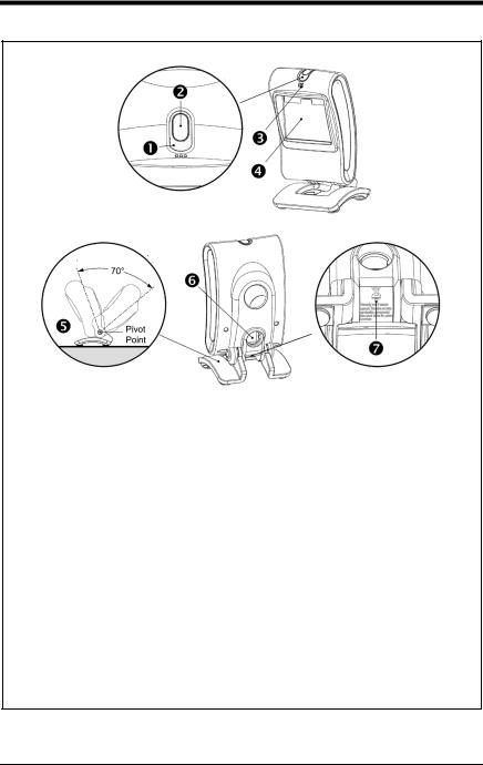
MS7580 Components
Item |
|
Item Description |
|
1 |
Blue and White LED |
See Visual Indicators (on page 20) |
|
|
|
|
|
2 |
Button |
Mode Select Button |
|
|
|
|
|
3 |
Speaker |
See Audible Indicators (on page 19) |
|
4 |
Window |
LED Aperture |
|
|
|
|
|
5 |
Adjustable Base |
|
|
|
|
|
|
6 |
Cable Connection |
10-pin RJ45, Female Socket, |
|
See Imager Pinout Connections (on page 49) |
|||
|
|
||
|
|
|
|
7 |
Cable Release |
See Cable Installation and Removal (on page 6) |
|
|
|
|
Note: The MS7580-124-EAS model is equipped with an integrated antenna for Electronic Article Surveillance (EAS) system support. See pages 39–47 for additional product information.
Figure 1. Imager Components
4

Labels
Each MS7580 has a label located near the top of the output window. This label provides the imager’s model number, date of manufacture, serial number, CE and caution information. Additional information has been molded into the underside of the imager's case. The following figure gives an example of the label and the molded text with their locations identified.
Figure 2. Label and Molded Text Samples
For North America:
CAUTION: To maintain compliance with applicable standards, all circuits connected to the scanner must meet the requirements of a NEC Class 2 power source or Limited Power Source as defined in UL 60950-1 Clause 2.5.
For Other Countries:
CAUTION: To maintain compliance with applicable standards, all circuits connected to the scanner must meet the requirements of a Limited Power Source as defined in IEC 60950-1 Clause 2.5.
Maintenance
Smudges and dirt on the imager's window can interfere with the imager's performance. If the window requires cleaning, use only a mild glass cleaner containing no ammonia. When cleaning the window, spray the cleaner onto a lint free, non-abrasive cleaning cloth and then gently wipe the window clean.
If the imager's case requires cleaning, use a mild cleaning agent that does not contain strong oxidizing chemicals. Strong cleaning agents may discolor or damage the imager's exterior.
5

Cable Installation and Removal
Installation
1.Insert the cable’s modular connector into the socket on the imager.
2.Pull gently on the cable strain relief to ensure the cable is installed.
Note: If the cable is not fully latched, the imager may power intermittently.
Figure 3. Installing the Cable
Removal
Turn the host power off and disconnect the power supply from the cable before attempting to disconnect the cable from the imager.
1.Locate the small pinhole on the imager near the cable connection point.
2.Bend a paperclip into the shape shown below.
3.Insert the paperclip into the pinhole and apply pressure to release the connector lock.
4.Pull gently on the strain-relief of the cable to remove the cable from the imager.
Figure 4. Disconnecting the Cable
MS7580-124-EAS Model Note
See page 39 for additional cable installation/removal instructions specific to the MS7580-124-EAS Genesis with integrated RF EAS antenna.
6
 Interface Installation
RS232
1.Turn off power to the host device.
2.Plug the interface cable’s modular connector into the socket on the imager.
3.Connect the other end of the cable to a dedicated COM port on the host device.
4.Plug the 12V power supply into the power jack on the cable.
5.Check the AC input requirements
of the power supply to verify the voltage matches the AC outlet. The outlet must be located near the equipment and easily accessible.
6.Connect AC power to the transformer.
7.The MS7580 will start to initialize.
The white and blue LED will alternately fade on and off for three seconds. When the imager has finished initializing, the imager will flash the white LED three times while simultaneously beeping three times. The low intensity blue LED will remain turned on.
8.Turn on power to the host device.
Figure 5. RS232
 See caution on page 5.
Installation Notes
•MS7580-124-EAS models are equipped with an integrated RF EAS antenna. See page 39 for additional cable installation instructions for EAS equipped Genesis models.
•Plugging the imager into a port on the host system does not guarantee that scanned information will be communicated properly to the host system. The imager is shipped from the factory configured with default settings. Please refer to the MetroSelect Single-Line Configuration Guide (PN 00-02544) or MetroSet™2’s help files for instructions on changing the imager’s configuration. In addition, please check that the imager and host system are using the same communication protocol.
The MS7580 requires 12V power to function for RS232 operation. Honeywell recommends using the external power supply shipped with the MS7580.
7

Keyboard Wedge
1.Turn off power to the host device.
2.Plug the interface cable’s modular connector into the socket on the imager.
3.Disconnect the keyboard from the host device.
4.Connect the “Y” ends of the communication cable to the keyboard and the keyboard port on the host device. A male/female adapter cable is supplied with the imager kit.
5.Plug the 12V power supply into the power jack on the cable.
6.Check the AC input requirements of the power supply to verify the voltage matches the AC outlet. The outlet must be located near the equipment and be easily accessible.
7.Connect AC power to the transformer.
8.The MS7580 will start to initialize. The white and blue LED will alternately fade on and off for three seconds. When the imager has finished initializing, the imager will flash the white LED three times while simultaneously beeping three times. The low intensity blue LED will remain turned on.
9.Turn on power to the host device.
Figure 6. Keyboard Wedge
 See caution on page 5.
Installation Note
Plugging the imager into a port on the host system does not guarantee that scanned information will be communicated properly to the host system. The imager is shipped from the factory configured with default settings. Please refer to the MetroSelect Single-Line Configuration Guide (PN 00-02544) or MetroSet2’s help files for instructions on changing the imager’s configuration. In addition, please check that the imager and host system are using the same communication protocol.
The MS7580 requires 12V power to function for Keyboard Wedge operation.
8

RS485
1.Turn off power to the host device.
2.Plug the interface cable’s modular connector into the socket on the imager.
3.Connect the other end of the cable to proper COM port of the host device.
4.Turn on power to the host device.
5.The MS7580 will start to initialize.
The white and blue LED will alternately fade on and off for three seconds. When the imager has finished initializing, the imager will flash the white LED three times while simultaneously beeping three times. The low intensity blue LED will remain turned on.
Figure 7. RS485
Installation Note
Plugging the imager into a port on the host system does not guarantee that scanned information will be communicated properly to the host system. The imager is shipped from the factory configured with default settings.
Please refer to the MetroSelect Single-Line Configuration Guide (PN 00-02544) or MetroSet2’s help files for instructions on changing the imager’s configuration. In addition, please check that the imager and host system are using the same communication protocol.
The MS7580 requires 12V power from the host for RS485 operation.
9
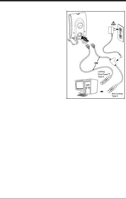
USB
1.Turn off power to the host device.
2.Plug the interface cable’s modular connector into the socket on the imager.
3.Plug the USB end of the cable into the host’s USB port.
Steps 4–6 are for VLink cables with a built in power jack and 12V external power supply. Skip to step 6 for USB direct connect cables receiving 12V power from the host.
4.Plug the power supply into the power jack on the VLink cable.
5.Check the AC input requirements of the power supply to verify the voltage matches the AC outlet. The outlet must be located near the equipment and be easily accessible.
6.Connect AC power to the transformer.
7.Turn on power to the host device.
8.The MS7580 will start to initialize. The white and blue LED will alternately fade on and off for three seconds. When the imager has finished initializing, the imager will flash the white LED three times while simultaneously beeping three times. The low intensity blue LED will remain turned on.
Figure 8. USB
 See caution on page 5.
Installation Notes
•MS7580-124-EAS models are equipped with an integrated RF EAS antenna. See page 39 for additional installation instructions for MS7580- 124-EAS models.
•The MS7580 meets the requirements for Full Speed USB hardware. The USB interface is configurable for Keyboard Emulation Mode, Bi-Directional Serial Emulation Mode or IBM OEM. The default setting for the USB interface is Keyboard Emulation Mode.
The MS7580 requires 12V power from the host for pass-through capabilities to function. See page 3 for a complete list of USB cable options.
10

•For information on configuring the MS7580 for USB Serial Emulation Mode or IBM OEM, refer to the USB section of the MetroSelect Single-Line Configuration Guide (PN 00-02544).
•Plugging the imager into a port on the host device does not guarantee that scanned information will be communicated properly to the host device. The imager is shipped from the factory configured with default settings. Please refer to the MetroSelect Single-Line Configuration Guide (PN 00-02544) or MetroSet2’s help files for instructions on changing the imager’s configuration. In addition, please check that the imager and host system are using the same communication protocol.
11

12

 Mounting the MS7580
Components of Adapter Kit 46-00911
|
|
|
|
Item |
|
Item Description |
Qty. |
A |
Adapter Plate |
1 |
|
B |
Locking Plate |
1 |
|
C |
Base Cover |
1 |
|
D |
M3 x .5 |
- 10 mm Flat Head Phillips Screw |
4 |
E |
M3 x .5 |
- 8 mm Flat Head Phillips Screw |
4 |
F |
#7 x 1.00 in. FHP Wood Screw |
3 |
|
G |
MS7580 Wall Mount Installation Guide |
1 |
|
Figure 9. 46-00911 Kit Components
Components of Wall Mount Kit 46-00913
|
|
|
Item |
Item Description |
Qty. |
A |
Wall Mount |
1 |
B |
#7 x 1.00 in. FHP Wood Screw |
2 |
C |
MS7580 Wall Mount Installation Guide |
1 |
Figure 10. 46-00913 Kit Components
13

Installation of Adapter Kit 46-00911
1.Remove the rubber feet on the bottom of the MS7580.
2.Attach the adapter plate to the bottom of the imager with the four M3 x .5 x 10 mm screws ( ) provided in the kit.
3.Attach the base plate to the adapter plate with the four M3 x .5 x 8 mm screws ( ) provided in the kit.
Figure 11
4.Before mounting the locking plate, consider the position the imager will rest when fully installed. There are two tabs located on the locking plate. These tabs indicate the two directions the imager may face when locked into position (see figure below).
Figure 12
14
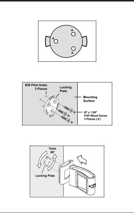
5.Use the locking plate as a guide to drill three #39 pilot holes (A) in the mounting surface.
Figure 13. Locking Plate (Not Drawn to Scale)
6.Secure the locking plate to the wall with the three #7 wood screws () provided in the kit.
Figure 14
7.Position the imager so the base plate sits flush over the locking plate. Twist the imager 90° counter-clockwise to lock the imager into place.
Figure 15
15

Installation of Wall Mount Kit 46-00913
1.Drill two #39 pilot holes in the mounting surface. The pilot holes should be centered vertically 44 mm apart.
2.Position the wall mount over the pilot holes with the arrow pointing up.
3.Secure the wall mount to the wall with the two #7 wood screws () provided in the kit.
Figure 16
4.Slide the imager's base under the upper corner tabs on the wall mount.
5.Slide the remainder of the base in and down behind the lower corner tabs.
Figure 17
16
 Operation
Modes of Operation
The MS7580 supports two standard modes of operation for scanning bar codes, automatic activation and manual activation scanning. Scanning while in the automatic activation mode can occur in either one of two configurable options, pass-through or presentation. Both the pass-through and the presentation options are enabled by default. With the default configuration, the imager operates in the pass-through state for 300 ms and then changes to the presentation state for additional decoding capability.
Automatic Activation Mode
Pass-through Scanning–The imager decodes only 1D and PDF bar codes. Scanning method:
1.Pass the bar code through the active scan area to scan, decode and send data.
Presentation Scanning–The imager decodes all 1D, PDF and 2D matrix codes
Scanning method:
1.Place the object in the IR activation range.
2.Hold the object's bar code in front of the scan window within the active scan area to scan, decode and send data.
Manual Activation
The imager decodes all 1D, PDF and 2D matrix codes.
Scanning method:
1.Press the button one time to activate linear targeting.
2.Press the button one time to activate linear targeting.
The MS7580 requires 12V power for pass-through capabilities to function.
The default configuration is recommended for optimum scan performance.
Imager configuration bar codes require the manual activation mode.
17
Loading...