


 Loading...
AT20, AT40, AT72D, AT87, AT88
AT Transformers
|
|
|
|
|
|
|
INSTALLATION INSTRUCTIONS |
|
||
APPLICATION |
|
|
Transformer voltage ratings (primary and secondary), |
|
||||||
|
|
|
|
|
wiring connection type, and fusing are listed in Table 1. |
|
||||
The AT20, AT40, AT72, AT87 and AT88 TRADELINE® |
|
The transformers are Underwriters Laboratories Inc. |
|
|||||||
Transformers are step-down transformers used primarily |
component recognized and Canadian Standards |
|
||||||||
for powering 24 Vac control systems. They can be used |
Association listed and meet NEC Class 2 not wet, Class |
|
||||||||
in any 24 Vac application that does not exceed the |
|
3 wet requirements as specified by NEMA Standard |
|
|||||||
transformer volt-ampere (VA) rating. |
|
DC-20. |
|
|
|
|||||
The TRADELINE® Transformers will replace all |
|
SPECIFICATIONS |
|
|
|
|||||
similar primary voltage requirements, equal or smaller VA |
|
|
|
|||||||
equivalent Honeywell and competitive transformers with |
|
|
|
|
|
|
||||
ratings and similar mounting configurations. |
|
Models: |
|
|
|
|||||
|
|
|
|
|
|
|
|
|||
|
|
|
|
|
See Table 1. |
|
|
|
||
|
|
Table 1. Transformer Model and Electrical Specifications. |
|
|
|
|||||
|
|
|
|
|
|
|
|
|
|
|
|
|
Primary |
|
|
Secondary |
Output at |
|
|
||
|
|
|
|
|
|
|
|
100 Percent |
Overload |
|
|
|
Voltage and |
|
|
|
|
|
|
||
Model |
|
Wiring Connection |
|
Voltage |
|
Wiring Connection |
Power |
|
||
|
Frequency |
|
|
Rating |
Protection |
|
||||
AT20a |
120 |
Vac, 50/60 Hz |
Two 9 in. (229 mm) |
24 Vac |
|
Two 9 in. (229 mm) |
20 VA |
Energy |
|
|
|
|
|
leadwires |
|
|
|
leadwires |
|
Limitedc |
|
AT40a |
120 |
Vac, 50/60 Hz |
|
|
|
40 VA |
|
|||
|
|
|
|
|
|
|
||||
|
240 |
Vac, 50/60 Hz |
|
|
|
|
|
|
|
|
AT72Da |
120 Vac, 50/60 Hz |
|
|
|
|
Two screw |
|
|
|
|
|
|
|
|
|
|
|
terminals |
|
|
|
|
240 |
Vac, 50/60 Hz |
Three 9 in. (229 |
|
|
|
|
|
|
|
|
|
|
mm) leadwires |
|
|
|
|
|
|
|
|
|
|
|
|
|
|
|
|
|
|
AT87Aa |
120 Vac, 50/60 Hz |
Two 13 in. (330 mm) |
|
|
|
|
50 VA |
|
|
|
|
|
|
leadwires |
|
|
|
|
|
|
|
|
208 |
Vac, 50/60 Hz |
|
|
|
|
|
|
|
|
|
|
|
|
|
|
|
|
|
||
|
240 |
Vac, 50/60 Hz |
|
|
|
|
|
|
|
|
AT88A |
120Vac, 50/60 Hz |
Two 12 in. (305 mm) |
24 Vac |
|
Two 12 in. (305 |
75 VA |
Fuse in |
|
||
|
|
leadwires |
|
|
|
mm) leadwires |
|
secondary |
|
|
|
208/240 Vac, 50/60 |
|
|
|
|
|
||||
|
Hz |
|
|
|
|
|
|
|
|
|
|
400 |
Vac, 50/60 Hz |
|
|
|
|
|
|
|
|
|
480 |
Vac, 50/60 Hzb |
|
|
|
|
|
|
|
|
a Transformer complies with 24 volt NEMA Standard DC-20.
b Available with female quick-connect terminals on all leadwires.
c Thermal fuses in primary on 208V/240V models for overload protection.
® U.S. Registered Trademark |
69-1641EF |
Copyright © 2002 Honeywell • All Rights Reserved |

AT20, AT40, AT72D, AT87, AT88 AT TRANSFORMERS
INSTALLATION
|
|
|
|
|
|
|
|
|
|
|
|
A |
|
B |
|
C |
|
D |
|
E |
|
|
in. |
mm |
in. |
mm |
in. |
mm |
in. |
mm |
in. |
mm |
AT40C |
2- |
61 |
7/8 |
22 |
1-3/4 |
44 |
2-3/16 |
56 |
2-7/8 |
73 |
|
13/32 |
|
|
|
|
|
|
|
|
|
AT87A |
2- |
61 |
1 |
25 |
1-3/4 |
44 |
2-1/16 |
52 |
3 |
76 |
|
13/32 |
|
|
|
|
|
|
|
|
|
When Installing This Product…
1.Read these instructions carefully. Failure to follow them could damage the product or cause a hazardous condition.
2.Check the ratings given in the instructions and on the product to make sure the product is suitable for your application.
3.The installer must be a trained, experienced service technician.
4.After installation is complete, check out product operation as provided in these instructions.
 WARNING
Electrical Shock Hazard.
Can cause severe injury, death or property damage.
Disconnect power supply before beginning installation to prevent electrical shock or equipment damage.
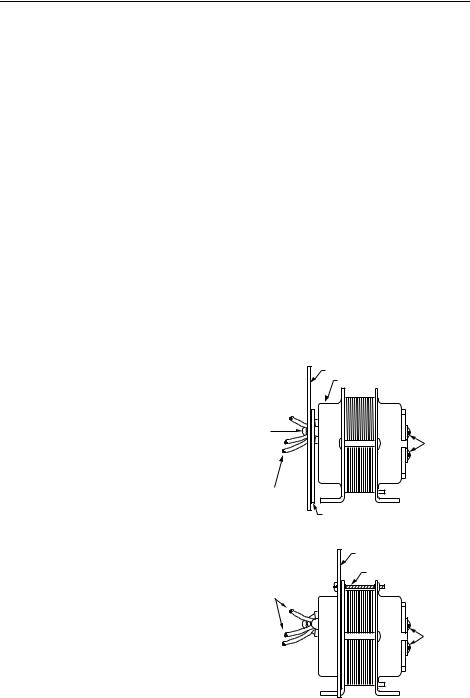
Mounting the AT20A and AT40A
Transformer
1.Mount the transformer to best suit the replacement application. The transformer may be mounted in one of three ways:
a. Use bolts in slots for direct mounting (Fig. 6).
PANEL
MOUNTING
USE WASHERS
IF NECESSARY
USE SCREWS OR BOLTS
THROUGH SLOTS (4) IN
MOUNTING FEET 
MOUNTING FOOT (2) |
M20655 |
Fig. 2. Foot mounting (AT20C shown).
c.Vertical channel mounting. Place frame over laminations as shown in Fig. 8 and bend tabs over to hold transformer securely in place.
Mount transformer through 3/16 in. (5 mm) holes in mounting feet.
HORIZONTAL FOOT MOUNTING
USE WASHERS IF NECESSARY
BEND OVER TABS (4) TO
SECURE TRANSFORMER
M20665
VERTICAL FOOT MOUNTING
M20654
Fig. 1. Use bolts in slots for panel mounting.
b.Horizontal channel frame. Place frame over laminations as shown in Fig. 7 and bend tabs over to hold transformer securely in place. Mount transformer over 3/16 in. (5 mm) holes in mounting feet.
USE WASHERS
IF NECESSARY
BEND OVER TABS (4) TO |
|
SECURE TRANSFORMER |
M20657 |
Fig. 3. Use horizontal channel frame for horizontal foot mounting; vertical channel frame for vertical foot mounting.
69-1641EF |
2 |
AT20, AT40, AT72D, AT87, AT88 AT TRANSFORMERS
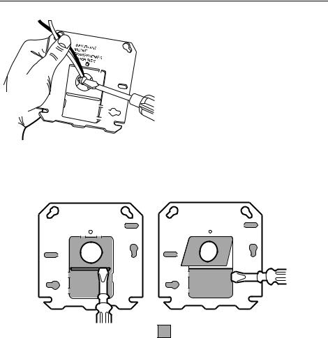
Mounting the AT72D Transformer.
Mount the transformer to meet the application. Use one of the methods illustrated. The transformer can be mounted in any position.
Foot Mounting.
1.Discard mounting plate.
2.Use screws or bolts through slots in mounting feet to fasten transformer to mounting surface.
Plate Mounting.
The mounting plate allows the transformer to be mounted on a 4 in. by 4 in. square or 4 in. octagonal junction box.
1.Remove the large center knockout in the mounting plate (Fig. 19).
2.Take transformer in one hand and mounting plate in the other hand. Keyhole slots on mounting plate should be up.
3.Place large knockout in mounting plate over primary leadwires and end bell of transformer. The small tab on the bottom center of the plate fits into the slot in the transformer mounting feet (Fig. 20).
4.Insert the mounting screw through the holes as illustrated.
5.Secure the plate to the transformer. Do not overtighten.
Mounting plate to transformer (Fig. 17).
The plate can be mounted to the transformer in one of two positions:
a.at the clamp on primary end bell (transformer all above plate);
b.at the laminations (transformer 3/4 above plate. To mount the plate at clamp on primary end bell (transformer all above plate):
1.Take mounting plate in one hand. Keep the keyhole slots up and the raised portion of the large center knockout toward you.
2.Insert the primary leadwires through the center hole in the plate.
3.Fit the hole in the plate over the clamp attached to the end bell. Clamp screw must be turned almost completely out.
4.With the plate in place over the clamp, tighten the screw securely against the rim of the round hold See Fig. 18. Avoid damaging the leadwires with the screwdriver.
To mount the plate at the laminations (transformer 3/4 above the mounting plate:
1.Remove the large center knockout in the mounting plate (see Fig. 19).
2.Take the transformer in one hand. Clamp on end bell should face you.
3.Take the mounting plate in the other hand. Keyhole slots should be up.
4.Place large knockout in mounting plate over primary leadwires and end bell. Small tab at the bottom of the center of the plate fits into the transformer mounting foot. Insert mounting screw through holes as shown in Fig. 20.
5.Secure plate to transformer. Do not overtighten screw.
Mounting Transformer and Plate to Electrical Box
The mounting plate can be mounted to 4 in. x 4 in. boxes with regular and irregular spaced mounting holes, to 2 in by 4 in. boxes and to 4 in. octagonal boxes. See Fig. 21.
1.Use the screws supplied with the electrical box.
2.Place them through the proper mounting holes in the plate and secure the transformer and plate to the box.
3.Punch out appropriate knockouts for plate mounting holes, if necessary.
NOTE: Transformer feet should always be outside of the junction box.
Clamp Mounting Using Junction Box Knockout
The transformer can also be clamp mounted using a junction box knockout, if desired. This mounting option does not require the use of the mounting plate. To mount the transformer within the knockout:
1.Insert the primary leadwires and clamp and screw on transformer end bell through suitable 1/2 in. (13 mm) knockout in junction box. Clamp screw must be turned almost completely out in order to get clamp through knockout.
2.Tighten clamp screw securely against rim of knockout. Avoid damaging the leadwires with the screwdriver.
PLATE MOUNTED AT CLAMP ON END BELL |
|
|
(ALL ABOVE PLATE MOUNTING) |
|
MOUNTING PLATE |
|
END BELL |
CLAMP |
SCREW |
SCREW |
|
AND |
TERMINALS |
CLAMP |
FOR |
|
SECONDARY |
|
CONNECTIONS |
LEADWIRES |
|
FOR PRIMARY |
|
CONNECTIONS |
|
|
RAISED PORTION OF LARGE CENTER KNOCKOUT |
PLATE MOUNTED AT THE LAMINATIONS (3/4 ABOVE PLATE MOUNTING)
MOUNTING PLATE
MOUNTING SCREW
LEADWIRES
FOR PRIMARY
CONNECTIONS
SCREW
TERMINALS
FOR
SECONDARY
CONNECTIONS
M20656
Fig. 4. Plate may be mounted to transformer in one of two positions (AT72D shown).
3 |
69-1641EF |
AT20, AT40, AT72D, AT87, AT88 AT TRANSFORMERS
M12126
Fig. 5. Tighten clamp securely against rim of round hole.
WITH RAISED PORTION OF KNOCKOUTS FACING YOU: |
|
1. PRY UP TOP SECTION OF LARGE KNOCKOUT |
|
BY INSERTING SCREWDRIVER FIRST AT ONE |
2. THEN PRY UP BOTTOM SECTION OF KNOCKOUT. |
SIDE OF SLOT AND THEN AT THE OTHER SIDE. |
3. REMOVE BOTH SECTIONS OF KNOCKOUT WITH PLIERS.
SHADED AREAS REPRESENT KNOCKOUTS |
|
AND SCREW SLOTS USED WITH 2 X 4 INCH |
M9188A |
OR OCTAGONAL OUTLET BOXES. |
Fig. 6. Removing large center knockout.
69-1641EF |
4 |
Loading...